1
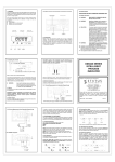
3.3 POWER SUPPLY
4.0 OPTION PODS
The Power supply rating will be indicated on the top of the instrument, ENSURE IT IS CORRECT FOR THE
APPLICATION.
THE MAINS SUPPLY TO THE EQUIPMENT MUST BE PROTECTED BY AN EXTERNAL 1 A FUSE AND A
SUITABLE SWITCH OR CIRCUIT BREAKER WHICH SHOULD BE NEAR THE EQUIPMENT.
NOTE: USE 600 VRMS CABLE (0.5 TO 1.5) mm².
4.1 INSTALLING PODS
Power must be removed from unit before adding/removing a pod. Slot 1 (alarm 1A and 1B) should be
positioned on the left side of the unit looking from the front to correspond to front panel alarm indicator,
Slot 2 (alarm 2A and 2B) is positioned on the right.
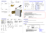
To install an Option Pod, slide back the cover to its next engaging position and push the pod connection
within the mating connector. To remove an Option Pod, disengage the supporting latch situated beneath
the pod by pushing the back cover forward, the pod can then be lifted away from the instrument connector.
4.2 DUAL RELAY POD. POD-3000/02000000
(+) L
The relay pod has two "change over"relays with a common wiper.
N (-)
3
4
NC
2
NO
1
NC
NO
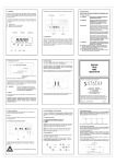
3.4 SENSOR CONNECTIONS
WIPER
Wires are retained by screws. Ensure that the exposed section of the wire is fully inserted and that no
loose strands are exposed.
5
All sensor connections are made via the five way "fast wiring" socket at the rear of the unit (wire size
(0.5 to 1.5) mm²).
NOTE: THERMOCOUPLE, RTD AND VOLTAGE INPUT A SCREENED CABLE IS RECOMMENDED FOR RUNS
GREATER THAN 10 m.
1
2
NOTE: USE 600 VRMS CABLE (0.5 TO 1.5) mm²
NOTE: ANY CIRCUIT WITH AN AC POTENTIAL GREATER THAN 33 VRMS AND 46.7 V PEAK MUST BE
PROTECTED WITH A 5 A(T) FUSE WHEN CONNECTED TO THIS POD.
To make a connection: Insert small screwdriver blade into tension clamp orifice (1), push and twist to
deflect clamp into open position. Do not lever screwdriver thus forcing connector body sideways. Insert
conductor tail sufficiently into (2) then release screwdriver. Ensure no loose wire strands protrude.
Page 3
Page 4