1
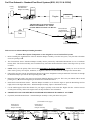
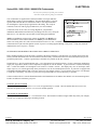
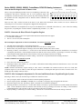
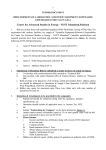
WIRING DIAGRAM
Series 5800/58000 6500/65000 6600/66000 Gas/EFI and Diesel CruiseMaster
GPH Instrument with LCD Totalizer
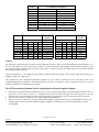
WIRE COLOR
RED
GREEN
BLACK
BLUE
WHITE
BROWN
WIRING LEGEND
FUNCTION
Ignition + 12VDC
Totalizer Memory Constant + 12VDC
Battery Minus (–) or Minus Buss *
Diagnostic Wire, (Not Connected)
Forward Flow Sensor
Not Connected
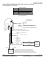
Single Sensor Installations
Totalizer Memory
Constant+ 12 VDC Source
(Negligible battery draw)
1/2 amp fuse
BLACK
WHITE
RED
GREEN
Totalizer
* Push-button Momentary OFF switches
Reset Switch available at most 'ACE Hardware' stores
(Momentary OFF)
** Do not use Back-lit, or Illuminated switches
To
Illumination
Circuit
+12VDC
BLUE (not connected, diagnostic wire)
BROWN(not connected in single sensor installations)
1/2 amp fuse
To Ignition Switch
(key ON = + 12VDC)
Cable Shield
BLACK
Connect Cable Shield
Drain Wire to
Vessel Bonding System
or
Engine Block
RED
R
W
CABLE
B
-12VDC
WHITE
BLACK
Flow
Sensor
+12VDC
*
BATTERY
* Ground refers to earth potential and is established by a
conducting connection through a conducting part of the
wetted hull, shaft, propeller,or engine block. Battery Minus is
called, "Ground" only when it's electrically connected to, "Earth".
12/6/2006
FloScan Instrument Company, Inc.
3016 NE Blakeley Street, Seattle, WA 98105
4001-372-00F
Tel: (206) 524-6625
Email: [email protected]
Fax: (206) 523-4961
Http://www.floscan.com