1
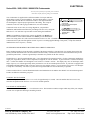
6.
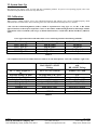
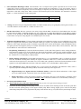
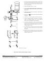
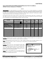
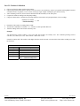
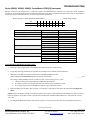
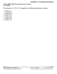
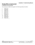
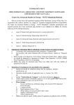
With the BLUE wire floating, (Disconnected) the pointer should read approximately:
10 GPH models
20 GPH models
32 GPH models
50 GPH models
100 GPH models
7.
9
18
28
45
90
40 LPH models
80 LPH models
160 LPH models
500 LPH models
35
70
140
450
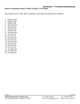
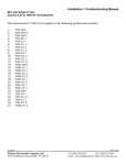
With the BLUE wire connected to the Instruments’ BLACK wire, the pointer should read approximately:
10 GPH models
20 GPH models
32 GPH models
50 GPH models
100 GPH models
0.5
1
2
2
5
40 LPH models
80 LPH models
160 LPH models
500 LPH models
2
5
10
20
NOTE: If readings are significantly Higher or Lower, the Instrument may be defective.
II. TEST FLOW SENSOR(S)
1.
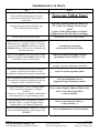
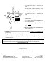
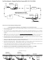
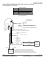
When the Blue Diagnostic wire is connected to Ground, (— 12 VDC) the instrument needle displays non-calibrated fuel flow
through the Forward Sensor. When the Blue wire is connected to + 12 VDC the needle shows the non-calibrated flow through the
Return Sensor. Calibration adjustments do not affect diagnostic readings.
2.
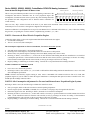
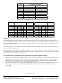
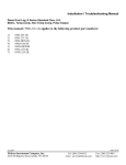
Using the chart below, record GPH and Gallon readings at IDLE, 800 RPM, 1000 RPM, 1500 RPM, 1800 RPM and 2200 RPM.
Circle S or F to indicate steady or fluctuating readings.
Blue Wire Æ connected to
— 12 VDC, (Forward Sensor)
S
S
S
S
S
S
F
F
F
F
F
F
Blue Wire Æ connected to
+ 12 VDC, (Return Sensor)
IDLE
800
1000
1500
1800
2200
S F
S F
S F
S F
S F
S F
NOTE: Diagnostic needle readings on the 0-5 & 0-10 GPH 5800(0) and 6500(0) series instrument’s, and all 6600(0) series
instruments show about 1/5th of actual fuel flow. On the 0-20 & 0-32 GPH 5800(0) & 6500(0) series instruments, the needle reads
about 1/3rd of actual fuel flow.
3.
4.
5.
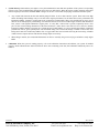
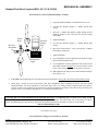
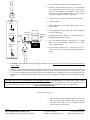
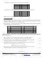
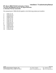
With your voltmeter set to a DC scale greater than 14 volts, measure between the RED (+12VDC) and
BLACK (Instrument ground) wires. With engine idling, measure and record the voltage reading.
___________VDC
Move the voltmeters’ negative lead to the WHITE (Signal) wire. With engine idling, measure and record the
voltage reading. Readings between 4 and 10 VDC usually indicate a good sensor.
___________VDC
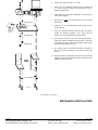
Stop the engine while observing the voltmeter. Voltage readings should fluctuate between a high of 9 to 12
VDC, and a low of 0 to 4 VDC as the flow sensors’ turbine slows to a stop.
___________VDC
NOTE: This may not be seen on a digital voltmeter.
6.
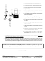
Move the voltmeters’ negative lead to the BROWN (signal) wire. With engine idling, measure and record the
voltage reading. Readings between 4 and 10 VDC usually indicate a good sensor.
___________VDC
(Continued on Reverse Side)
03/10/2006
FloScan Instrument Company, Inc.
3016 NE Blakeley Street, Seattle, WA 98105
4001-104-00
Tel: (206) 524-6625
Email: [email protected]
Fax: (206) 523-4961
http://www.floscan.com