1
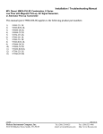
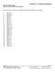
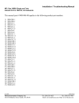
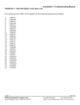
AC Signal Generator Input
Switch Settings
Drive Ratio
Green Switch
Poles
4
4
4
8
8
8
30
30
30
0.5 to 1
1 to 1
2 to 1
0.5 to 1
1 to 1
2 to 1
0.5 to 1
1 to 1
2 to 1
Red Switch
1
3
7
3
7
F
E
D
B
0
0
0
0
0
0
0
1
3
Alternator Input
The signal from the alternator input comes from one alternator winding before it’s rectified. You may notice fluctuations in
the tachometer due to belt slippage and varying alternator load.
No Tachometer reading at lower RPMs
Until engine RPM reaches a certain point, the alternators output voltage will be too low for the tach to read. Installing a 12
VDC light across a DC power source (+12 VDC to ground) will increase the alternator load slightly, and cause its output
voltage to increase to a usable level.
Calibration
The tachometer can be calibrated by two methods:
I.
Calibrate to an existing tachometer. Rotate the RED and GREEN knobs on the back of the instrument until the two
tachometers agree with each other. The accuracy of this method depends on the accuracy of the existing tachometer at the
RPM to which you calibrate. Most analog tachometers are accurate to either ±50 RPM or ±100 RPM, with the center of the
scale being the most accurate. If you set the calibration here and find a difference toward the minimum or maximum ends of
the analog tachometer scale, it is probably due to the nonlinearity of the analog meter movement. This method may not be as
accurate as #2 below.
II.
1. Calculate the number of pulses per crank shaft revolution. To find the number of crank shaft pulses per revolution, divide
the diameter of the engines crank shaft pulley by the diameter of the alternator pulley, and multiply by the number of
alternator pulses.
Diameter of Crank Shaft Pulley
--------------------------------------Diameter of Alternator Pulley
x
Number of Alternator Pulses
=
Pulses per Revolution
2. Locate the number of pulses per crank shaft revolution from the table, select the number closest to the actual pulses per crank
shaft revolution. Set the RED and GREEN switches on the back of the instrument accordingly.
Example:
A Motorola alternator has 12 pulses (12 pulses per revolution)
Crank shaft pulley = 10” diameter
Alternator pulley = 4” diameter
12 x 10/4 = number of pulses per revolution
12 x 2.5 = 30 pulses per revolution
FloScan Instrument Company, Inc.
3016 NE Blakeley Street, Seattle, WA 98105
Tel: (206) 524-6625
email: [email protected]
Fax: (206) 523-4961
http://www.floscan.com