1
i.
!
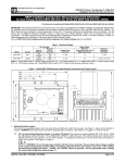
SIMPLIFIED SETUP AND OPERATING INSTRUCTIONS
IMPORTANT – You must read these simplified operating instructions before you proceed.
These instructions are to be used as a reference only and are not intended to replace the
detailed instructions provided herein. You must read the Safety Warning before proceeding.
Be sure to read Important Application Information on page 7.
1.
AC POWER.
Use 115VAC rated controls on 115VAC and 230VAC
rated controls on 230VAC. For dual input voltage
controls, be sure the AC line jumpers (J1 and J2
on upper PC board) are both set for the correct
AC line voltage 115 or 230VAC. Connect the AC power
to terminals L1 and L2. Be sure the AC power is
disconnected when making connections to control.
Do not bundle AC power and motor wires with any
other wires to control. When the power is turned on
the “PWR” LED will light and the “ST” LED will flash.
Connect ground (earth) to green ground screw located
on the control chassis.
2.
MOTOR LEADS.
Connect the three motor leads to terminals “U,” “V,” and “W.”
Be sure motor is wired for proper voltage: 208-230VAC only.
Motor cable length should not exceed 100 feet – special reactors
may be required – consult factory.
1
3.
MOTOR FREQUENCY SELECTION.
Control is factory set for 60 Hz and 50/60 Hz motors. For 50 Hz motors, completely
remove jumper J1 on lower PC board. (Note: In 50 Hz mode, DECEL trimpot becomes
adjustable boost.) For 120 Hz over speed operation, place jumper J1 in the 120 Hz
position.
4.
TRIMPOT SETTINGS.
The KBVF has been factory set for most applications. For readjustment procedures,
see sec. IX, p. 24.
5.
POTENTIOMETER CONNECTIONS.
Connect the 5K ohm potentiometer to
terminals P1, P2 and P3 as shown
in fig. 10A, p. 19.
6.
SIGNAL FOLLOWING.
For signal following, an isolated
0-5VDC must be used.
Connect signal (POS) to P2 and signal (NEG) to P1 (Note: For signal following, the MIN
trimpot must be set to zero - CCW). Warning! Do not earth ground any input signal
wiring.
7.
FUSING.
Install a fuse or circuit breaker in the AC line. Fuse each conductor not at ground
potential. See sec. VI, p. 21 for recommended fuse size.
2