1
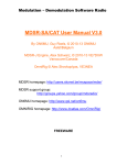
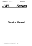
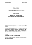
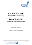
User Manual
AT-CAN-MINI
© port GmbH, Halle 31.07.99;
All rights reserved
The contents of this documentation were generated and checked carefully by engineers of
port GmbH (in following port). port however accepts no responsibility for damage
caused by the use of this documentation. In particular performance characteristics and
technical data given in this document may not be constituted to be guaranteed product
features in any legal sense.
port has the right to modify the products described or their documentation at any time
without prior warning, as long as these changes are made for reasons of reliability or
technical improvement.
All rights of this documentation lie with port. The transfer of rights to third parties or
duplication of this document in any form, whole or in part, is subject to written approval
by port. Copies of this document may however be made exclusively for the use of the
user and his engineers. The user is thereby responsible that third parties do not obtain
access to these copies.
The soft- and hardware designations used are mostly registered and are subject to copyright.
Copyright ©
1999 port GmbH
Regensburger Straße 7c
D-06132 Halle
Tel. +49 345 - 777 55 0
Fax. +49 345 - 777 55 20
E-Mail [email protected]
1. Technical Data
AT-CAN-MINI provides a CAN network interface for PC-AT compatible computers. It
is designed as a short PC slot card with dimensions 100mm x 150mm. PC interface is a
ISA direct connector. The CAN network connection is made by an SUB-D-9male and
SUB-D-9female connector physically it is designed according to ISO/DIS 11898 and the
recommendations of CiA (CAN in Automation e. V.). After plug in the card into the PC
slot the CAN connectors are available at the PC’s backboard.
The CAN interface is optically isolated against the PC voltage level.
AT-CAN-MINI occupies 32 addresses in the PC’s I/O address space. The starting
address is selectable by jumpers.
The CAN controller can generate interrupts at the PC bus. The interrupt number is also
selectable by jumpers.
As CAN controller the BASIC CAN SJA1000 by Philips is used.
Port GmbH provides C-library functions for simple functions to program the controller.
The library is foreseen and tested with the following compilers:
BORLAND C++ 2.0 and
BORLAND TURBO C 2.01
PC-Interface
ISA-direct board connector
CAN-Interface
2 x SUB-D-9 according ISO/DIS 11898 and CiA recommendation
CAN-Controller
SJA1000
CAN-driver
SJA1000 or SI9200
address area
32 byte between 200h - 3E0h
Interrupts
IRQ3 - IRQ7 selected by jumper
Dimension
100mm x 150mm
Table 1, technical data overview
Page 4 of 13
AT-CAN-MINI User Manual
Version: 1.2 Status: Rel
BR1
W1
BR2
U4
Y1
BR4
JP2
120 Ohm
BR3
80H
100H
40H
20H
ADR
200 H+
INT
JP1 3 4 5 6 7
JP3
BR5
Figure 1, jumpers and soldering bridges
AT-CAN-MINI User Manual
Version: 1.2 Status: Rel
Page 5 of 13
2. Hardware
Following is an overview schematic of the board.
CANbus
Opto Barrier
and Driver
Basic CAN
Controller
Address
Decode
Data
Driver
Interrupt
Logic
AT ISA-8 Bus
Figure 2, AT-CAN-MINI schematic
2.1. Addressing
AT-CAN-MINI uses an 32 byte address window in the I/O address space of the PC. In
this area the controllers register are mapped.
Begin address of this I/O area is located between 200h and 3E0h. With jumper JP3 it can
be freely assigned in steps of 32 byte, 20h.
Page 6 of 13
AT-CAN-MINI User Manual
Version: 1.2 Status: Rel
1-2
3-4
5-6
7-8
Adresse
I
I
I
I
I
I
I
I
I
I
I
I
I
I
I
200h
220h
240h
260h
280h
2A0h
2C0h
2E0h
300h
320h
340h
360h
380h
3A0h
3C0h
3E0h
I
I
I
I
I
I
I
I
I
I
I
I
I
I
I
I
I
Table 2, I/O address jumpering with JP3
Legend:
I ... jumper applied
2.2. CAN-Controller
As CAN controller the Philips Basic CAN SJA1000 clocked with 16 MHz is used.
The clock is generated at board.
Together with the CAN driver circuit SJA1000 bit rates up to 1 MBaud are possible.
The controller is used in the Intel-Mode. Signals are driven from a PAL (22V10).
By using a CAN controller which handles all layer 2 protocol the user only has to provide
data in the transmit buffer. The controller then transmits the message automatically. Also
receiving is done automatically. Received messages must only be read from the registers.
2.3. Address-/data multiplexor
The used CAN controller SJA1000 has an shared data/address bus. To use the 32 registers of the SJA1000 address lines A0...A4 of the PC are used. These lines must be multiplexed with data lines D0..D7.
Address/data multiplexor is built by the circuit U6 (unidirection address) and U5 (bidirectional data).
Control signals "DEN*" and "AEN*" as also the correct timing are created by the PAL
U8.
AT-CAN-MINI User Manual
Version: 1.2 Status: Rel
Page 7 of 13
2.4. Connection to the Bus
The physical connection to the CAN bus is realized by two parallel connected SUB-D-9
connectors according to DIN 41652.
Pin
Signal
Description
1
2
3
4
5
6
7
8
9
CAN_L
GND
(GND)
CAN_H
(V+)
reserved
CAN_L (dominant low)
ground
reserved
reserved
ground (optional)
CAN_H (dominant high)
reserved (error line)
external power supply 7V - 13V (optional)
Table 3, pin assignment for the SUB-D-9 CAN
The two connectors make it possible to grind the bus through the AT-CAN-MINI.
2.5. Optical isolation
Optical isolation is provided by the coupler U2 for transmitting and U1 for receiving.
Galvanical isolation between the 5 V Power Supply and the CAN driver circuit with optocoupler U2 is done with the DC/DC converter W1.
If this is not necessary following changes has to be made:
components: U1, U2 and W1 do not mount;
soldering bridges: BR1, BR2, BR3 and BR4 close;
If the board is already assigned with U1, U2 and W1, then the soldering bridges BR2,
BR3 and BR4 are not accessible in order to protect the components.
If a galvanic connection is desired and the components already mounted, the soldering
bridge BR1 must be closed.
The slot plate with mounted DSUB connectors is normally connected with ground of the
PC by bridge BR5. Within industrial PC’s with no connection between housing and processor ground the bridge must be disrupted.
2.6. CAN driver
As a CAN driver the PCA82C250T or SI9200 can electively be used. Both are pin compatible. Driver and opto coupler build a CAN interface according to ISO/DIS 11898.
If the SI9200 is used, the resistor R2, reducing the steepness of signal edges with
PCA82C250T, is not necessary.
Steepness is proportional to the used resistor.
Page 8 of 13
AT-CAN-MINI User Manual
Version: 1.2 Status: Rel
Following relations are valid:
value R2
result
0 (PIN 8 at GND)
open
10kOhm .. 100kOhm
highest steepness
standby modus
slope control
Table 4, influence of steepness
Formula: calculation of edge steepness
t slope = − 3 * 10− 5 + 36 [V / s]
Standard resistor with 10 KOhm yields in a steepness of 30V/ s.
2.7. Interrupt
To achieve the capability to generate interrupts from the CAN channel one of the interrupt lines must selected with the "INT" jumper JP1.
It can be selected from the lines IRQ3 to IRQ7. IRQ5 is preferred.
1-2
3-4
5-6
7-8
9-10
IRQ
I
IRQ3
IRQ4
IRQ5
IRQ6
IRQ7
I
I
I
I
Table 5, interrupt jumpering with JP1
I..jumper applied
Attention !
Only one jumper must be applied.
AT-CAN-MINI User Manual
Version: 1.2 Status: Rel
Page 9 of 13
3. Software
3.1. Introduction
The CAN controller with the AT-CAN-MINI is driven in I/O mode, That means that communicating with the board is done by 32 addresses in the PC’s I/O address range.
Port GmbH provides with the C-library can_util.lib some functions to easy access the
CAN controller. Following functions are delivered:
Function
Short description
CAN_PortInit()
CAN_PortMask()
CAN_PortStatus()
CAN_PortTxRdy()
CAN_PortRxRdy()
CAN_PortTx()
CAN_PortRx()
CAN_PortIRQ_E()
CAN_PortIRQ_D()
CAN_PortIRQRead()
initialization of the CAN controller
programming acceptance and mask registers
read controller status
check transmit readiness
check receive readiness
send message
read message
enable interrupts
disable interrupts
read interrupt register
Module number
To be able to use the library also with boards with more then one CAN controller, a module number is provided with all calls to functions. Because AT-CAN-MINI has only one
controller
Module number is always 1.
Following conventions are used:
•
•
TRUE = 1
FALSE = 0
The provided examples only should show how to use the library functions. Therefore no
sanity checks are within it.
3.1.1. Data types and structures
Some of the functions get or deliver data types BYTE. It is declared as
typedef unsigned char BYTE;
and allocates one byte in memory.
Page 10 of 13
AT-CAN-MINI User Manual
Version: 1.2 Status: Rel
telegramm is a structure, containing all necessary informations for a CAN message:
message
is the CAN identifier from or to other CAN nodes
11 Bit in a bit field
rtr
identifier for an Remote Transmit Request (RTR)
1 Bit in a bit field
count
number of bytes to send or received
4 Bit in a bit field
daten
With CAN up to 8 bytes can be transfered. The message data
are stored in an 8 byte array of unsigned char.
3.2. Content of disk
With the provided disk are the following files:
File
Description
can_util.h
can_util.lib
canrec.c
cansend.c
readme
Header file for CAN functions
library file
example 1
example 2
notes for using examples
Table 6, content of supplied disk
AT-CAN-MINI User Manual
Version: 1.2 Status: Rel
Page 11 of 13
4. Appendix
4.1. Example canrec.c
The example waits for an incoming CAN message and displays the contents of the message. It runs until the user hits one key. More notes to the example are in the file readme.
#include
#include
#include
#include
#define
#define
#define
#define
<stdio.h>
<dos.h>
<bios.h>
"can_util.h"
OFF
ON
MOD1
MOD2
0
1
1
2
BYTE bus0 =
0x89;
BYTE bus1 =
0xEB;
BYTE mask =
0xFF;
BYTE acc =
0xFF;
int port_adr = 0x280;
int modul =
MOD1;
main()
{
can_telegramm rx;
int z;
int i;
int schalter = OFF;
/* Modul Nr. 1 */
/* Modul Nr. 2 */
/*
/*
/*
/*
/*
/*
Bustiming Register 0 */
Bustiming Register 1 */
Maskenregister */
Akzeptanzregister */
Adresse I/O-Port */
Modulnummer */
/* Empfangsstruktur */
/* Durchlaufzähler */
/* Zählvariable */
/*--- CAN-Controller initialisieren ----------------------------------*/
CAN_PortInit (port_adr, MOD1, bus0, bus1);
CAN_PortMask (port_adr, MOD1, mask, acc);
/*--- periodisch empfangen ----------------------------------------*/
while (schalter == OFF){
while (!CAN_PortRx(port_adr, modul, &rx) && schalter == OFF){
delay(1);
z++;
if (z > 5000){
printf("warte0);
z = 0;
}
if (bioskey(1))
schalter = ON;
}
if (schalter == OFF){
printf("Message: %d0,rx.message);
printf("Count: %d0,rx.count);
for (i = 0; i < rx.count; i++){
printf("Daten hex: %x0,rx.daten[i]);
printf("Daten char: %c0,rx.daten[i]);
printf("Daten dezimal: %d0,rx.daten[i]);
}
}
}
}
Page 12 of 13
AT-CAN-MINI User Manual
Version: 1.2 Status: Rel
4.2. Example cansend.c
The programm periodically sends a message. Message data are entered over the command line. It runs until the user hits one key. More notes to the example are in the file
readme.
#include
#include
#include
#include
#include
#include
#define
#define
#define
#define
BYTE
BYTE
BYTE
BYTE
<stdio.h>
<dos.h>
<bios.h>
<stdlib.h>
<string.h>
"can_util.h"
OFF
ON
MOD1
MOD2
0
1
1
2
/* Modul Nr. 1 */
/* Modul Nr. 2 */
bus0 = 0x89;
bus1 = 0xEB;
mask = 0xFF;
acc = 0xFF;
/*
/*
/*
/*
int port_adr = 0x280;
int modul = MOD1;
Bustiming Register 0 */
Bustiming Register 1 */
Maskregister */
Acceptanzregister */
/* Adresse I/O-Port */
/* Modulnummer */
main (int argc, char *argv[])
{
can_telegramm tx;
int z;
int schalter = OFF;
/*--- Sendestruktur beschreiben -------------------------------------*/
tx.message = atoi(argv[1]);
tx.count = atoi(argv[2]);
strcpy(tx.daten, argv[3]);
/*--- CAN-Controller initialisieren -----------------------------------*/
CAN_PortInit(port_adr, modul, bus0, bus1);
CAN_PortMask(port_adr, modul, mask, acc);
/*--- periodisch senden ------------------------------------------------*/
while (schalter == OFF){
while (!CAN_PortTx(port_adr, modul, &tx) && (schalter == OFF)){
delay(1);
z++;
if ( z > 5000){
printf("warte0);
z = 0;
}
if (bioskey(1))
schalter = ON;
}
}
}
AT-CAN-MINI User Manual
Version: 1.2 Status: Rel
Page 13 of 13
Table of Contents
1. Technical Data
.
.
.
.
.
.
.
.
.
.
.
.
.
.
.
.
.
.
.
.
.
4
2. Hardware . .
.
.
.
.
.
.
.
.
.
.
.
.
.
.
.
.
.
.
.
.
.
6
2.1. Addressing .
.
.
.
.
.
.
.
.
.
.
.
.
.
.
.
.
.
.
.
.
.
6
2.2. CAN-Controller
.
.
.
.
.
.
.
.
.
.
.
.
.
.
.
.
.
.
.
.
7
2.3. Address-/data multiplexor
.
.
.
.
.
.
.
.
.
.
.
.
.
.
.
.
.
7
2.4. Connection to the Bus
.
.
.
.
.
.
.
.
.
.
.
.
.
.
.
.
.
.
8
2.5. Optical isolation
.
.
.
.
.
.
.
.
.
.
.
.
.
.
.
.
.
.
.
.
8
2.6. CAN driver .
.
.
.
.
.
.
.
.
.
.
.
.
.
.
.
.
.
.
.
.
.
8
2.7. Interrupt .
.
.
.
.
.
.
.
.
.
.
.
.
.
.
.
.
.
.
.
.
.
.
9
. .
.
.
.
.
.
.
.
.
.
.
.
.
.
.
.
.
.
.
.
.
.
10
3.1. Introduction .
.
.
.
.
.
.
.
.
.
.
.
.
.
.
.
.
.
.
.
.
.
10
Module number .
.
.
.
.
.
.
.
.
.
.
.
.
.
.
.
.
.
.
.
.
.
10
3.1.1. Data types and structures .
.
.
.
.
.
.
.
.
.
.
.
.
.
.
.
.
10
3.2. Content of disk .
.
.
.
.
.
.
.
.
.
.
.
.
.
.
.
.
.
.
.
.
11
4. Appendix .
.
.
.
.
.
.
.
.
.
.
.
.
.
.
.
.
.
.
.
.
12
4.1. Example canrec.c .
.
.
.
.
.
.
.
.
.
.
.
.
.
.
.
.
.
.
.
12
4.2. Example cansend.c
.
.
.
.
.
.
.
.
.
.
.
.
.
.
.
.
.
.
.
13
3. Software
.
.
AT-CAN-MINI User Manual
Version: 1.2 Status: Rel
Page 3 of 13