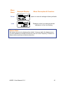
1
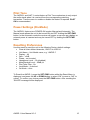
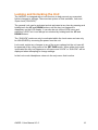
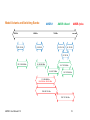
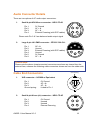
`` User Manual v1.0 User Manual AWDR-1 Contents: Foreword .......................................................................................................... 1 Safety Instructions ........................................................................................... 1 Product Contents ............................................................................................. 1 General Description ......................................................................................... 2 True Diversity ................................................................................................... 3 Product Overview............................................................................................. 4 Audio Output Sockets ................................................................................... 4 Headphone Monitoring Socket ..................................................................... 4 The LED Indicators....................................................................................... 5 RSSI Active ‘A’ and Active ‘B’ (Tri-colour LED)......................................... 5 Receiver Battery Status (Tri-colour LED) .................................................. 5 Transmitter Battery Status ........................................................................ 5 Antenna Input Socket A & B ......................................................................... 5 Push Button Controls ................................................................................... 6 Frequency Label........................................................................................... 7 Battery Compartment ................................................................................... 7 LCD Display ................................................................................................. 8 Using the AWDR-1......................................................................................... 11 Tuning the Receiver ................................................................................... 11 Tuning By Frequency .............................................................................. 11 Saving Custom Frequencies ................................................................... 11 Tuning By UHF TV Channel and Sub-Channel....................................... 12 Unit Name .................................................................................................. 13 Display settings .......................................................................................... 13 SCAN ......................................................................................................... 13 AUDIO ........................................................................................................ 13 Phase ......................................................................................................... 14 Headphone Volume.................................................................................... 14 Mute Level / Squelch: “MUTELV” ............................................................... 14 Unit Information: “INFO” ............................................................................. 14 Pilot Tone ................................................................................................... 15 Power Settings (On-Mode) ......................................................................... 15 Resetting Preferences ................................................................................ 15 Locking and Unlocking the Unit .................................................................. 16 Further Technical Information ........................................................................ 17 Antenna Data for Flexible Wire Antennae .................................................. 17 Model Variants and Switching Bands: ........................................................ 18 Audio Connector Details ............................................................................. 19 Cable End Connectors ............................................................................... 19 Standard Receiver Cables Details.............................................................. 20 Technical Specifications ................................................................................ 23 RF Transmission System ........................................................................... 23 Audio Performance..................................................................................... 23 Received Signal Strength Indicators (RSSI) ............................................... 23 Battery Status Indicator .............................................................................. 23 AWDR-1 User Manual V1.0 i TX Low Battery Indicator ............................................................................ 24 Headphone Monitoring Output ................................................................... 24 Powering .................................................................................................... 24 Connectors ................................................................................................. 24 Dimensions................................................................................................. 24 Accessories ................................................................................................ 24 AWDR-1 User Manual V1.0 ii Foreword Thank you for choosing Audio Wireless We aim to offer the best quality products alongside a quick and reliable service for all our customers. Please take some time to read our instruction manual to ensure you get the most out of our equipment. Safety Instructions Please read these instructions carefully before using the unit to avoid injury and damage to your AWDR-1 unit. Always include these instructions when passing the unit on to third parties Never open the electrical units; if the units are opened then the warranty becomes null and void. Protect the unit from damp and wet conditions, as water entering inside can cause damage to the unit. Use only a slightly damp cloth to clean the unit. Do not use any cleansing agents or solvents. Product Contents 1 2 1 1 AWDR-1 Diversity Receiver Antenna Quick Start Guide Carrying Case AWDR-1 User Manual V1.0 1 General Description The AWDR-1 Diversity Receiver offers the greatest flexibility and sound quality for crews, operators and sound recordists, whether working internationally or simply under challenging RF conditions. Its sophisticated structure comes in a lightweight yet rugged, CNC machined aluminium case, designed for extra strength and durability as well as the ability to withstand the heavy demands of location use. The unit requires two AA batteries which fit into its unique battery compartment designed for fast and easy battery replacement by an easy-twist compartment cover, with a reassuring click-stop mechanism. Alternatively it can be externally powered from any 10-18V source. Product Features: Switching bandwidth up to 120MHz Tunable in 25kHz steps Digitally switchable RF front-end Top-level flexibility for international working Compact design, tough, lightweight aluminum case 2 x AA alkaline batteries provide approximately 5 hours of operating time or using lithium batteries even longer Easy-twist battery compartment cover, with click-stop reassurance External powering capable with adaptor leads Balanced user adjustable audio output Audio output level from +6dBV to -42dBV Headphone - Stereo/mono mini-jack with monitor-volume control Easy operation by backlit LCD with programmable functions Continuous Rx and Tx low battery status indicators RF, Pilot-tone and noise operated mute Reliable, professional-grade connectors Please Note: To ensure best performance it is recommended to only use the AWT-1 transmitter series with the AWDR-1 diversity receiver series. AWDR-1 User Manual V1.0 2 True Diversity The Audio Wireless diversity receiver systems give a dramatic improvement to signal dropout problems found in dead spots when compared to other simple standard or antenna switching receivers. This is because the true diversity receiver makes use of two RF signals, and when one antenna is receiving a weak signal, the other antenna will be receiving a stronger signal, offering greater reliable coverage. The problem of signal dropout is usually caused where the direct and reflected signals happen to interfere and cancel each other out at the antenna. Within the Audio Wireless diversity receiver the combining circuitry automatically discards the output from the receiving sections of weaker RF signal before it can degrade the audio output. Should the signal strengths be similar the audio outputs are combined to improve the signal to noise ratio. This audio mixing gives a 3dB improvement over conventional switched diversity receivers and results in a greater operating range. By fully processing(demodulating) both signals and not simply switching at the Antenna level a robust and reliable AF signal can be transmitted with no audible dropouts and the best signal to noise ratio can be maintained over a large reliable operating area. Furthermore the same result could not be achieved by just connecting two antennas in parallel, either directly or through simple amplifiers. The relative phase of the signals from the two antennas would change as the transmitter was moved and cancellation effects would occur at the summing point. Antenna Antenna Receiving Module RXA Signal Strength Signal Strength Receiving Module RXB Comparator Output AWDR-1 User Manual V1.0 AF Signal Selector Output 3 Product Overview TOP VIEW Receiver Battery Indicator Transmitter Battery Indicator RSSI for RXB RSSI for RXA Antenna Socket B Antenna Socket A Audio Output Socket (Model Specific) Headphone Monitoring Socket Audio Output Sockets There are two types of Audio Output connectors are available: Large 6-Pin LEMO™ connector (pictured above) Multi-way 4-pin connector HR4 Both connectors provide balanced audio output and external dc input connections to the receiver. The balanced audio output level is user adjustable from +6dBV to -42dBV to suit varying device input requirements. External powering may be done by using dedicated RCP cables. Please Note: Ensure that P48 is turned off on a mixer/camera before connecting it to the AWDR-1. Headphone Monitoring Socket The AWDR-1 has a unique headphone design that auto detects Stereo or Mono Jacks when inserted into the 3.5mm socket and does not cause an electrical short or any loss of audio level. The Headphone is user adjustable to suit headphones impedances as low as 16. Please Note: Make sure that the Headphone Amplifier is OFF (00) when not used. High levels of volume can damage your hearing, always set the Monitoring level low before connecting headphones and then adjust as required. AWDR-1 User Manual V1.0 4 The LED Indicators RSSI Active ‘A’ and Active ‘B’ (Tri-colour LED) A tri-colour LED above each antenna socket continuously display the Received Signal Strength Indicators (RSSI) and shows which half of the Diversity Receiver is Active. Receiver Battery Status (Tri-colour LED) A tri-colour LED continuously displays the internal/external battery status. Transmitter Battery Status Transmitter low battery-warning Red-LED lights up/flashes when the supply voltage of the corresponding TX has fallen to below ~1.0 Volt. The Low Battery Warning period depends upon the type of battery used. Antenna Input Socket A & B The miniature 50 SMA coaxial sockets are used as the antenna input connectors, the detachable matching antennas are fitted by a simple screw-on action. AWDR-1 User Manual V1.0 5 FRONT VIEW Audio Output Socket Antenna Socket A Antenna Socket B Multi-function LCD Display Frequency Label (Model Specific) Push Button Controls Battery Compartment Push Button Controls All user adjustments to the AWDR-1 are made via three push buttons. Primarily use the UP and DOWN to scroll through menu’s and the SET-PWR to select choices. Alternatively at any time the SET-PWR button can be held down to turn the receiver OFF (and back ON) and by holding both the UP and DOWN buttons the receiver can be LOCKED. AWDR-1 User Manual V1.0 6 Frequency Label Indicates the tuning range of the receiver, where it is possible to tune to frequencies within this range in steps of 25 kHz. Alternatively the user may tune the Receiver to standard UHF TV channels with pre-coordinated sub channels. Battery Compartment The AWDR-1's AA batteries are held in place by a captive, easy-twist compartment cover, with a click-stop mechanism for quick, reliable changes possible by feel alone. Simply open the battery cover by rotating clockwise, insert 2 AA batteries (please follow the polarity guidance) into the compartment. The click system reassure that the compartment is fully opened or closed. To Open Rotate clockwise To Close Rotate anti-clockwise Please Note: When inserting the batteries please remember to follow the polarity guidance indicated on the rear face of the unit. Remove the batteries when the unit will not be used for extended periods of time. AWDR-1 User Manual V1.0 7 LCD Display -50 -40 -30 -20 -10 0 –Φ LIMIT AF RF A RF B PILOT MUTE CH MHZ The backlit multifunction LCD display provides clear access to all the available control menus and functions of the AWDR-1. Permanently displayed, irrespective of the currently selected menu, is the continuous AF metering of the audio signal level and RSSI level of each antennae’s RF signal and the battery level icons. Please Note: The display backlight and LED indicators (when active) illuminate for approximately 15 seconds from last button press and subsequently turn off to optimize battery use. By default the following main menus are available: Menu Name Example Display -50 -40 -30 -20 -10 Menu Description & Function 0 AF RF A B Frequency Displays Transmission Frequency and allows for adjustment when selected MHZ -50 -40 -30 -20 -10 0 AF RF A B Channel CH Displays Transmission Channel & SubChannel as well as allowing for adjustment when selected -50 -40 -30 -20 -10 0 AF RF A B Name AWDR-1 User Manual V1.0 Displays Unit Name and allows for adjustment when selected 8 Menu Name Example Display -50 -40 -30 -20 -10 0 Menu Description & Function AF Display Option for displaying or hiding certain Menus -50 -40 -30 -20 -10 0 AF RF A B Scan -50 -40 -30 -20 -10 0 AF RF A B Audio -50 -40 -30 -20 -10 0 B Phase HeadPhone B B MUTE -50 -40 -30 -20 -10 Allows for adjustment of the Head-Phone volume 0 AF RF A Mute / Squelch Option for inverting the phase of the output signal 0 AF RF A -50 -40 -30 -20 -10 Set the audio output gain from +6dB to -42dB in 6dB steps –Φ AF RF A -50 -40 -30 -20 -10 Facility to find quiet frequencies (or Channels) to use or noisy signals to avoid Allows for adjustment of the Mute (aka Squelch) level 0 AF RF A B Info. -50 -40 -30 -20 -10 Gives Unit Info 0 AF RF A Pilot B PILOT MUTE -50 -40 -30 -20 -10 Option to turn off the Pilot tone system 0 AF RF A On-Mode AWDR-1 User Manual V1.0 B Allows for adjustment of the Power-On mode 9 Menu Name Example Display -50 -40 -30 -20 -10 Menu Description & Function 0 AF RF A B Reset -50 -40 -30 -20 -10 Option to return all settings to factory defaults 0 AF RF A Lock B Displays current Lock state and allows adjustment of the Lock Setting Please Note: All menus are set to be displayed by default. However within the display menu it is also possible to choose to show only one out of the Frequency, Channel or Name menus and hence hide the other two. AWDR-1 User Manual V1.0 10 Using the AWDR-1 Tuning the Receiver There are two methods available for tuning the receiver allowing both complete flexibility and convenience. These are tuning by Frequency or by numbered UHF TV Channel with pre-coordinated Sub-Channels. Tuning By Frequency By default the Frequency menu is the first menu that appears upon turning ON the unit. On the Frequency menu the currently used frequency for transmission is displayed on the screen in MHz. 1. To tune, press the SET-PWR button to start the frequency select mode. In this mode the displayed frequency flashes. 2. Use the UP or DOWN buttons to scroll through the entire switching bandwidth in steps of 25 kHz. 3. To save the selected frequency press the SET-PWR button to store, the confirmatory “SAVED” message will appear. Saving Custom Frequencies The receiver can save up to 24 frequencies to the user customisable channel bank listed as “VAR XX” in the channel menu. To store a frequency - simply repeat the above but after selecting the frequency quickly press the SET-PWR button again whilst the “SAVED” message appears. Then select the required custom channel, named “VAR 01” to “VAR 24” and hit the SET-PWR button to select and display the confirmatory “SAVED” message. Please Note: There are 24 user customizable channels available, which after being set in the frequency mode menu, are then accessible via the channel mode menu, explained further below. Remember to change display mode to “All” for both menus to be available. Resetting the unit will clear all user channel pre-sets. AWDR-1 User Manual V1.0 11 Tuning By UHF TV Channel and Sub-Channel Each UHF TV channel (8MHz wide in EU) has up to 12 pre-coordinated subchannels (labelled A through to M, excluding the letter I). These have been calculated to avoid interference between them, maximizing the use of the available spectrum. (Sub-Channels A to H are the best eight). 1. To tune to a UHF TV channel, simply hit the SET-PWR button whilst on the Channel Menu to start the channel select mode. In this mode the displayed channel information flashes. 2. Use the UP or DOWN buttons to scroll through all the available channels and press the SET-PWR button to select one. As well as the model dependent range of UHF TV channels are the user customisable “VARXX” channels available. 3. Use the UP or DOWN buttons to scroll through the available subchannels and press the SET-PWR button to select your choice and “SAVED” message appears to confirm your selection. Please note, each UHF TV channel may have up to 12 pre-coordinated sub-channels, e.g. “A>M”. Please Note: Channel 38 (606-614 MHz), commonly used in the UK is presented with 2 sets of sub-channels. The Audio Wireless co-ordinated “A>M” set and the alternative JMFG “38-XX” option that grants a set of sub-channels numbered from 1-10. Do not mix sub-channels from both sets. For users in the UK it should be noted that channel 38, is the only general purpose channel recommended for use by the JMFG in public spaces. AWDR-1 User Manual V1.0 12 Unit Name For convenience and quick distinction between units it is possible to give the receiver a 6 character alpha-numerical name. The characters available are A-Z, 0-9 and 3 special characters; “*”, “-”and “ ”. By default the name given is the Units Model Number, e.g. “AWDR-1”. Display settings In certain usage situations it may be preferred to hide some of the menus. For example, if the receiver is to only be tuned using frequencies it may be preferable to hide the channel menu, or vice versa when tuning with UHF channels and sub-channels. Alternatively, if the device has been tuned and will not need to be adjusted for an extended period of time it may be of benefit to display only the Unit’s Name to quickly distinguish amongst other units. The Menu Display options available are: All – Display all Menus; Frequency, Channel and Name. Freq – Display only the Frequency Menu & not the Channel or Name Menus. Chan – Display only the Channel Menu & not the Frequency or Name Menus. Name – Display only the Name Menu & not the Frequency or Channel Menus. To change the displayed menus, simply hit the SET-PWR button whilst on the Display Menu to start the Display menu select mode and cause the current Display option to flash continuously. Then use the UP or DOWN buttons to cycle to the required setting and press the SET-PWR button to select your choice and display the confirmation “SAVED” message. SCAN With the Scan function it is possible to find a quiet, usable channel or when the “Signal” options is selected, a signal or noisy channel can be found to avoid. On the Scan Menu press the SET-PWR button and then with the UP and DOWN buttons select whether to scan for noise or for a free channel. Once SCAN is selected the unit will automatically search through all available pre-coordinated channels and then in 100 kHz steps starting from the lowest available frequency. Once the SCAN stops on an appropriate channel press the SETPWR buttons to accept or press the UP button to reject and continue with the scan. AUDIO The Audio output level of the AWDR-1 is user adjustable between +6dBV to – 42dBV to suit varying device input requirements. To do so press SET-PWR on the AUDIO menu, adjust with the UP and DOWN buttons and press SET-PWR to confirm. AWDR-1 User Manual V1.0 13 Phase A phase reverse facility is provided within the AWDR’s menu system to help the users when mixed equipment might be out of PHASE or when hard wired boom and Radio mics may have different phase. To match the phase of other equipment used with the AWDR-1 is the ability to change the phase of the output. Simply select whether to INVERT the phase or keep it NORMAL. Please Note: When the phase invert is selected, the “Φ” icon will appear on the screen. Headphone Volume To adjust the volume of the monitoring output, simply select the Menu with SETPWR, then use the UP and DOWN buttons until the required level is reached and select it by pressing SET-PWR once more. Please Note: Make sure that the Headphone Amplifier is OFF (00) when not required. WARNING: High levels of volume can damage your hearing, always set the Monitoring level low before connecting headphones and then adjust as required. Mute Level / Squelch: “MUTELV” The receiver is fitted with an adjustable MUTE LEVEL to mute the receiver in cases of noisy background levels or as a very useful tool when setting the receivers in a multi-channel set of 8-12 in a given TV band. This is to avoid any unwanted receiver mute activation for a reliable operation. Unit Information: “INFO” Within the INFO menu it is possible to view the following unit information; Serial Number - Unit Unique and same as on the rear casing Model name - E.g. “AWDR-1” Max switching frequency - In MHz, model specific Min switching frequency - In MHz, model specific Dc volt level - The voltage reading of the battery Software version number - The Software version number AWDR-1 User Manual V1.0 14 Pilot Tone The AWDR-1 and AWT-1 series feature a Pilot Tone mechanism to only output the audio signal when it is received from the corresponding matching transmitter. Use the menu to enable or disable the feature if required. PILOT ON is recommended. Power Settings (On-Mode) The AWDR-1 features two POWER-ON modes; Manual and Automatic. The Manual mode allows the unit to be turned ON and OFF holding the SET-PWR button. In the Automatic mode the receiver will power on as soon as a battery or external power is inserted and may be turned OFF by holding the SET-PWR button. Resetting Preferences Use this menu to reset the unit to the following Factory default settings: Clear all User defined channels, VAR-01 to VAR-24 Unit Name – Unit Model name, e.g. “AWDR-1” Display – All Gain – +6dB Phase – not inverted Headphone Level – 00 (disabled) Mute/Squelch Level – 00dB µV Pilot Tone Filter - On Lock Mode – Unlocked On Mode – Auto To Reset the AWDR-1, press the SET-PWR button whilst the Reset Menu is displayed, and press the UP or DOWN button to select “OK” to reset or “NO” to cancel. To confirm your choice press the SET-PWR button. After resetting the “SAVED” message will be displayed. AWDR-1 User Manual V1.0 15 Locking and Unlocking the Unit The AWDR-1 is designed with a Lock function to help prevent any unwanted further changes to settings. There are two options of lock available, Lock and Super-Lock (“SULOCK”). The general Lock can be activated and de-activated at any time by pressing and holding both the UP and DOWN buttons until the key icon appears or disappears on the LCD display. It can also be set via the LOCK menu and selecting “LOCK” but it can always be unlocked by holding both the UP and DOWN buttons. The “SULOCK” mode can only be activated within the Lock menu and can only be UNLOCKED by removing the power from the unit. Lock mode restrict any changes to any of the menu options but the unit can still be powered off by a long press of the SET-PWR button. When either lock mode is activated the key icon appears on all menus and “LOCK” or “SULOCK” will be displayed when attempting to change settings. In the Lock mode Headphone volume is the only menu that is active. AWDR-1 User Manual V1.0 16 Further Technical Information Antenna Data for Flexible Wire Antennae COLOUR CODE CENTRE FREQUENCY (MHz) USABLE FREQUENCY RANGE (MHz) ACTIVE LENGTH (mm) BLUE 560 510 - 620 125 BLACK 650 600 - 720 106 RED 750 700 - 800 88 NOTE: RX AND TX ANTENNA LENGTHS ARE SAME. Active length is the length of the antennae from the connecting socket housing to the tip. AWDR-1 User Manual V1.0 17 Model Variants and Switching Bands: 500 MHz AWDR-1 600 MHz BE1: 510-542 AWDR-1dband AWDR-1plus 700 MHz U1: 600-632 800 MHz G2: 720-748 G4: 755-785 G3: 730-766 FB1: 510-566 MHz U5: 600-660 MHz G5: 710-766 MHz U6: 660-715MHz G6: 730-785 MHz C1: 600-698 MHz USA/CAN Exc. 608-614 MHz FB2: 600-715 MHz FB3: 710-785 MHz AWDR-1 User Manual V1.0 18 Audio Connector Details There are two options of AF audio output connectors: 1. Small 4-pin HR4 Hirose connector - HR10-7P-4S Pin 1: Pin 2: Pin 3: Pin 4: 0V Ground AF + Φ AF – Φ External Powering (with RCP cables) 1 4 2 3 Please note Pin 2 & 3 are balanced audio output signal 2. Large 6-pin L6 LEMO connector – ERY.2C.306.CLL Pin 1: Pin 2: Pin 3: Pin 4: Pin 5: Pin 6: AF+ Φ Unused External Powering (with RCP cables) Unused 0V Ground AF – Φ 2 1 3 4 6 5 Please Note: Please note the above chassis mounted connectors are shown as viewed from the external face, whereas the following cable connectors shown are from the solder side. Cable End Connectors 1. XLR connector – NC3MX or Equivalent Pin 1: Pin 2: Pin 3: Ground spring: 2. Ground spring 0V Ground AF + Φ AF – Φ Linked to Pin 1 2 1 3 Small 4-pin Hirose (dc) connector – HR10-7P-4P Pin 1: Pin 2: Pin 3: Pin 4: AWDR-1 User Manual V1.0 0V Ground Unused Unused External Powering 1 4 2 3 19 3. Small 4-pin Hirose (AF) connector – HR10-7P-4P Pin 1: Pin 2: Pin 3: Pin 4: 4. 0V Ground AF + Φ AF – Φ External Powering 1 4 2 3 Large 6-pin L6 LEMO connector – FFA.2C.306.CLAL52 Pin 1: Pin 2: Pin 3: Pin 4: Pin 5: Pin 6: AF+ Φ Unused External Powering (with RCP cables) Unused 0V Ground AF – Φ 4 1 3 2 3 2 Standard Receiver Cables Details RC-1HR4: Audio output cable to suit AWDR-1 (HR-4) receivers, balanced AF output to XLR 1 1 2 2 3 3 XLR HR-4 (AF) 4 RCP-1HR4: Audio output and external powering cable for AWDR-1 (HR-4) receivers, external powering (10-18 V dc) with 4-pin Hirose (dc) connector, with balanced AF output to XLR 1 2 XLR 1 3 2 HR-4 (AF) 3 1 4 2 HR-4 (dc) 3 4 AWDR-1 User Manual V1.0 20 2RCP-1HR4: Dual audio output and external powering cable to power two AWDR-1 (HR-4) receivers, external powering (10-18 V dc) with 4pin Hirose (dc) connector, with 2x balanced AF output to XLR HR-4 (AF) (1) 1 2 XLR (1) 1 3 2 3 4 1 2 XLR (2) 3 1 2 1 3 2 4 3 HR-4 (dc) 4 HR-4 (AF) (2) RC-1L6: Audio output cable to suit AWDR-1 (L6) receivers, balanced AF output to XLR 1 1 2 2 3 3 4 5 XLR 6 L6 LEMO AWDR-1 User Manual V1.0 21 RCP-1L6: Audio output and external powering cable for AWDR-1 (L6) receivers, external powering (10-18 V dc) with 4-pin Hirose (dc) connector, with balanced AF output to XLR 1 1 2 2 3 XLR 3 4 1 5 2 6 HR-4 (dc) 3 L6 LEMO 4 2RCP-1L6: Dual audio output and external powering cable to power two AWDR-1 (L6) receivers, external powering (10-18 V dc) with 4-pin Hirose (dc) connector, with 2x balanced AF output to XLR 1 2 3 L6 LEMO (1) 1 2 XLR (1) 3 4 5 1 6 2 XLR (2) 3 1 2 3 L6 LEMO (2) 1 2 HR-4 (dc) 3 4 4 5 6 AWDR-1 User Manual V1.0 22 Technical Specifications RF Transmission System Carrier Range (to order) 470 to 790MHz Channels up to 4800, switchable in 25 kHz steps Switching Range up to 120MHz Modulation System F3EGN Minimum Channel Spacing 300 kHz Reference Deviation 40 kHz Adjacent Channel Rejection >100dB Mute Level 4-steps: 0dBµ (nom), 5dBµ, 15dBµ, 25dBµ Audio Performance System S/N Ratio >100dB Frequency Response 60Hz to 18kHz, ±2dB Distortion <0.2% THD AF Level Balanced variable output,-42dBV to +6dBV Received Signal Strength Indicators (RSSI) (Active A and Active B) Green signal >25µV Amber signal >5µV Red signal <5µV No light Muted Battery Status Indicator Green >2.2V Amber >1.9V Red <1.8V No light Battery Flat (unit OFF) AWDR-1 User Manual V1.0 23 TX Low Battery Indicator Red LED lights when TX battery < 1.0V Headphone Monitoring Output AF Level 50mW Impedance 16 Ohms Powering Battery Type IEC LR6 (MN1500) 2 x AA Current Consumption 250mA (max) @ 3V Battery Life approximately 5 Hours with alkaline battery External Power 10.0 to 18V dc (with ‘RCP’ cables) Connectors Antenna Inputs SMA connectors (x2) Audio Output 4-pin Hirose or large 6-pin Lemo connector Monitor Output 3.5mm jack socket (accepts mono or stereo) Dimensions Width 62mm (max) Depth: 20mm Height 114mm (max) Weight: 200gr Accessories Supplied: Antennas (x2) Quick start guide Optional extras RC: Receiver balanced audio output cable RCP: Receiver balanced audio output cable for external powering 2RCP: Dual balanced audio output cable for external powering of two receivers HSA: Hot shoe adapter Audio Wireless Ltd reserves the right to change specifications without notice, as part of its policy of continuous product development. © Audio Wireless Ltd. AWDR-1 User Manual V1.0 24 Printed in the UK Published August 2013 AWDR-1 User Manual V1.0 Elstree Film Studios Phoenix 5 Andrew Mitchell Building Shenley Road, Borehamwood Hertfordshire WD6 1JG UK 25