1
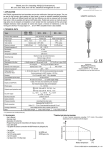
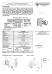
2.6. DERATING DIAGRAMS Sliding Sleeve pT [bar] 40 -40 ø40 s=41 15 0 ~110 25 Version with flange 50 0 100 130 TM[°C] s=55 RPH-112 Pressure[pT] version [TM] for all models (exept PP flanged) BSP 1 1/2" 0.2...3m 18 AT[°C] 70 55 I350 mA L I L 100 mA I L Ł 1 mA 45 35 TRICLAMP (ISO 2852) 95 105 115 130 T M [°C] Pipe Coupling For 3-wire DC models [IL] load current p T [bar] 6 5 -20 R_D DN40 110 1 0 50 0 90 R_E DN50 RD 65x1/6 RD 78x1/6 T M [°C] For models with Polypropylene flange pT=process pressure TM =medium temperature TA[°C] 70 55 2.9 MATERIALS Special PVC EPDM 1.4571 Polyamid, glassfibrereinforced 115 130 TM[°C] For 2-wire AC models [TA] ambient temperature [TM] medium temperature 2.7. RESPONSE TIME DIAGRAM WHEN GETTING FREE Response time [S] 35 30 25 20 15 10 5 0 0 Polyamid, glassfibrereinforced 1.4571 1.4571 Klingerit 1.4571 1.4571 1.4571 Klingerit 1.4571 3. INSTALLATION Prevent the device from any mechanical damage. vertical position horisontal position 2000 4000 6000 8000 10000 viscosity [cSt] 2.8 DIMENSIONS ø40 SW=41 R-4– ~110 ~110 R-400– BSP / NPT 1" ø40 SW=41 125...3000 69 BSP / NPT 1" 4/2 ♦ TÜV-A 03 ATEX 0021X ♦ rcm4004a0600h_04 For positioning the fork-tines, use the marking on the hexagonal neck. MARK • Use a TEFLON (PTFE) tape to aid the positioning of the fork-tine • If the fork-tine position is irrelevant, use the sealing ring provided