1
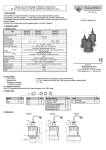
4.1.2. Integral cable version R – 4 – 2 This version is with 4 wire cable equipped. Only one of the black and brown wires is used, dependent on the operating mode (High or Low) Provide also a terminal block connection for the unused wire. Low viscosity liquids On applications, where the forktines are easily freed from the process medium, any of the mountings shown to the right is possible. High viscosity liquids On applications, where the forktines are not freed easily from the process medium, the horizontal mounting is recommended. brown brown R blue black N black L1 green/yellow L1 R blue N green/yellow Junction box Junction box LOW-level limit switch HIGH-level limit switch 4.2. 3 WIRE DC VERSIONS R–4–3 R–4–4 In case of overload caused by short circuit, transistor will switch on and off, and LED will start to blink. 4.2.1. Connector version R – 4 – 3 Installation options LED "M" - Operation mode H= High - level limit switch 3 L= Low - level limit switch 2 1 H M L Threaded version Critical distances (xmin > 5 mm) 4.2.1.1. Wiring diagram for 3 wire DC version with connector in case of relay application For pipe mounting, fork-tines must be parallel to the direction of flow PNP-wiring NPN-wiring Terminal block cover can be rotated in 90° steps to ensure appropriate cable positioning 4.2.1.2. Wiring diagram for 3-wire DC version with connector for PLC application Switching point and switch differential for water at 25 °C + Switching point as well as the switch differential depends on liquid density and mounting position 24V DC IN 4. ELECTRICAL CONNECTIONS 4.1. 2 WIRE AC VERSIONS COM R – 4 – 1 connector R – 4 – 2 cable PNP-wiring 4.2.2. Integral cable version DO NOT POWER UP THE DEVICE WITHOUT A LOAD CONNECTED IN SERIES WITH THE UNIT AND WITHOUT GROUNDING IT R white 2 1 N 1 L1 LOW-level limit switch white R black R black - blue Terminal block cover can be rotated in 90° steps to ensure appropriate cable positioning R blue + Junction box LOW-level limit switch HIGH-level limit switch NPN mode + brown HIGH-level limit switch - brown Junction box 3 N + brown L1 2 R–4–4 4.2.2.1. Relay application PNP mode 4.1.1. Connector version R – 4 – 1 3 PLC (A-B sink input, OMRON SYSMAC,...) white - brown white R black black - blue Junction box LOW-level limit switch R + blue Junction box HIGH-level limit switch TÜV-A 03 ATEX 0021X ♦ rcm4004a0600h_04 ♦ 4/3