1
University Program Design Laboratory Package User Guide
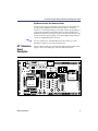
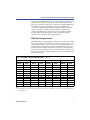
MAX_PB1 & MAX_PB2 Push-Buttons
MAX_PB1 and MAX_PB2 are two push-buttons that provide active-low
signals and are pulled-up through 10-KΩ resistors. Connections to these
signals are easily made by inserting one end of the hook-up wire into the
push-button female header. The other end of the hook-up wire should be
inserted into the appropriate female header assigned to the I/O pin of the
EPM7128S device.
MAX_SW1 & MAX_SW2 Switches
MAX_SW1 and MAX_SW2 each contain eight switches that provide logiclevel signals. These switches are pulled-up through 10-KΩ resistors.
Connections to these signals are easily made by inserting one end of the
hook-up wire into the female header aligned with the appropriate switch.
The other end of the hook-up wire should be inserted into the appropriate
female header assigned to the I/O pin of the EPM7128S device. The switch
output is set to logic 1 when the switch is open and set to logic 0 when the
switch is closed.
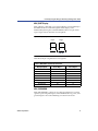
D1 through D16 LEDs
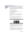
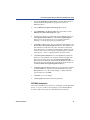
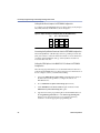
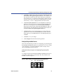
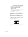
The UP 1 Education Board contains 16 LEDs that are pulled-up with a
330-Ω resistor. An LED is illuminated when a logic 0 is applied to the
female header associated with the LED. LEDs D1 through D8 are
connected in the same sequence to the female headers (i.e., D1 is
connected to position 1, and D2 is connected to position 2, etc.). LEDs D9
through D16 are connected in the same sequence to the female headers
(i.e., D9 is connected to position 1, and D10 is connected to position 2, etc.).
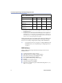
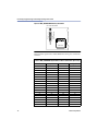
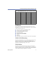
See Figure 3.
Figure 3. LED Positions
Female
Header
Position
1
2
3
4
5
6
7
8
8
LEDs
D1
D5
D2
D6
D3
D7
D4
D8
Female
Header
Position
1
2
3
4
5
6
7
8
LEDs
D9
D13
D10
D14
D11
D15
D12
D16
Altera Corporation