1
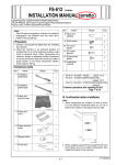
RU-509 Relay Unit
INSTALLATION MANUAL
Applied Machine:C7000/C7000P/C6000/C70hc
COLOR PRESS:(71ppm/71ppm)/(70ppm/70ppm)/(60ppm/60ppm)
Product Code:A1DU/A204/A1DV/A205
I.Precaution
III.Installation Procedure
1. Select a flat and stable place for installing the
machine.
2. Lifting the machine in an awkward position or
transporting it in a poorly balanced position could
result in personal injury. When transporting the
machine, assign an adequate number of persons
to the job and ensure that each person can take a
good position of not being excessively loaded.
(mass: approx. 60 kg)
1. Remove the mirror mat and the locking tapes
from the external parts.
2. Check the external appearance of the machine.
Mirror mat
II.Accessory parts
No.
Name
Shape
Q’ty
Locking tapes
1. Installation
plate /1
Locking tapes
2
A1TTIXC002CA
2. Installation
plate /2
A2A2IXC002CA
3. Open the front door and remove the locking tapes
and the bundled item.
2
Locking tapes
A2A2IXC001CA
3. Installation
plate /3
Locking tapes
2
A1TTIXC004CA
4. Clamp
1
A1TTIXC005CA
5. TP screw
M4x6
8
6. TP screw
M4x8
2
7. Sems II screw
M4x8
1
8. Installation
manual
9. Power cord
(Except
for Europe)
Locking
tapes
Bundled
item
A2A2IXC003CA
4. Remove the connector cover on the left side of
the main body. (1 screw)
1
1
Connector cover
A2A2IXC004CA
E-1
A2A2955000
7. Adjust the height of the RU-509.
(1) Align the height of the main body and RU-509
as shown in the picture.
5. Install the installation plates /1 and /2 to the main
body. (each 2 places: TP screw M4x6: each 2 pcs)
TP screws
M4x6
TP screws
M4x6
Front
Aligning position
Installation
plates /2
Back
Aligning position
Installation
plates /1
A2A2IXC005CA
6. Connect 4 connectors of the RU-509 to the connectors of the main body.
Note:
Before setting the RU connector wiring harness to
the main body, be sure to push it into the RU side.
Otherwise it is nipped.
A2A2IXC010CA
Note:
• Turn 4 height adjustment screws (back and
front) shown in the picture to adjust the height.
• Turning the screw clockwise rises the RU.
main body
Front
Connector
Height adjustment screws
Connectors
Back
A2A2IXC006CA
Height adjustment screws
A1TTIXC014CA
E-2
8. Align the top and bottom holes of the RU-509 to
the installation plates /1 pins, and lock them by
sliding the RU-509 to the back.
10.Plug in the RU-509 power cord and fix it in the
clamp. (Sems II screw M4x8 : 1)
Power cord
Top
Clamp
Main body
Installation
plate /1
RU-509
A1TTIXC017CA
Holes
IV. Serial Number Registration
Register the serial number of the RU-509 installed to
the main body
The location of the serial number is shown in the figure below.
Installation
plate /1
Bottom
A2A2IXC007CA
9. Fix the RU-509 and the installation plates /3 with
the screws. (TP screw M4x8: 2)
Top
Installation plate /3
Serial No.
A2A2IXC009CA
Step
TP screw M4x8
1. Plug the power cord of the main body and
the RU-509 into the outlet and turn ON the
Main power switch.
Bottom
Installation plate /3
2. Enter Service mode.
Note:
Refer to procedures in the Service Manual to
enter into the Service Mode.
3. Touch the "System Setting" key.
4. Touch the "Serial Number Setting" key.
TP screw M4x8
5. Touch the "Finisher" key to enter the serial
number setting screen. (Select the installation order key.)
A2A2IXC008CA
6. Enter the serial number of the RU-509 and
touch the "OK" key. (Use the "Shift" key to
switch between upper case letters and lower
case letters.)
7. Touch the "Return" key and then touch the
“Exit” key.
E-3