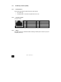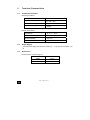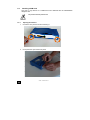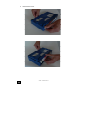
1
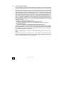
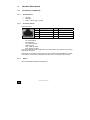
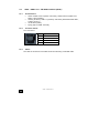
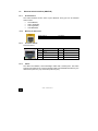
ONE20
Installation Manual
Version B
July 2008
http://www.oneaccess-net.com
1
ONE20 - Installation Manual
OneAccess
28 rue de la Redoute
92260 Fontenay aux Roses
France
The law of 11 March 1957, paragraphs 2 and 3 of article 41, only authorizes, firstly,
’copies and reproductions strictly reserved for use by copyists and not for general
use and, secondly, analyses and short quotations for the purpose of example and
illustration. Therefore, ’any representation or reproduction, entire or partial, made
without the consent of the author or his representatives is illegal’ (paragraph 1 of
article 40).
Any such representation or reproduction, made in any manner whatsoever, would
therefore constitute an infringement of the law as sanctioned by articles 425 and in
accordance with the penal code.
Information contained in this document is subject to change without prior notice and
does not constitute any form of obligation on the part of OneAccess.
OneAccess and the distributors can in no case be held responsible for direct or
indirect damage of any kind incurred as a result of any error in the software or
guide.
Every care has been taken to ensure the exactitude of information in this manual. If
however you discover an error, please contact OneAccess After Sales Service
division.
July 2008 Issue, revision B
2
ONE20 - Installation Manual
How to Read this Manual
The present document is broken down into 7 chapters.
Chapter 1 – Safety Instructions
This chapter provides the safety instructions for use and installation of the router.
Chapter 2 – Directives and Standards
This chapter details the list of standards, which the router complies with.
Chapter 3 – Router Description
This section describes the router front and rear panels and the associated technical
characteristics.
Chapter 4 – Interface Description
This section describes the router interfaces.
Chapter 5 – Technical Characteristics
This section describes technical characteristics such as operating conditions.
Chapter 6 - Installation
This chapter describes how to mount a daughter-board and gives instructions to
connect the router.
Chapter 7 – Power-up
This chapter describes the device power-up and how to monitor the self-test
progress.
Appendix – Connection description
These chapters provide the pin-out of cables that are compatible with the router.
3
ONE20 - Installation Manual
Table of Contents
ONE20................................................................................................................................................1
Installation Manual .............................................................................................................................1
1
SAFETY INSTRUCTION ..............................................................................................................5
1.1
Connection to Power Supply ...................................................................................................5
1.2
Safety Level Interface..............................................................................................................6
2
DIRECTIVES AND STANDARDS................................................................................................7
2.1
Declaration of Conformity........................................................................................................7
2.2
Standards ................................................................................................................................8
2.3
FCC Statement (USA) ...........................................................................................................10
3
ROUTER DESCRIPTION ...........................................................................................................11
3.1
Front Panel ............................................................................................................................12
3.2
Rear Panel ............................................................................................................................13
3.3
4
4.1
Console port (CONSOLE) .....................................................................................................15
4.2
ADSL - ADSL 2/2 + - RE-ADSL Interface (ADSL).................................................................16
4.3
Ethernet Switch Interface (SWITCH).....................................................................................17
4.4
5
S0 Backup interface (ISDN) ..................................................................................................18
TECHNICAL CHARACTERISTICS............................................................................................19
5.1
Climatic Environment ............................................................................................................19
5.2
Power Supply ........................................................................................................................19
5.3
Dimensions............................................................................................................................19
6
7
Motherboard ..........................................................................................................................14
INTERFACE DESCRIPTION......................................................................................................15
INSTALLATION .........................................................................................................................20
6.1
Install the WLAN antenna......................................................................................................20
6.2
Wall mounted installation ......................................................................................................21
6.3
Installing a SIM Card .............................................................................................................22
6.4
Connections ..........................................................................................................................25
POWER UP ................................................................................................................................26
APPENDIX A - CONSOLE CABLE ......................................................................................................27
4
ONE20 - Installation Manual
1
Safety Instruction
The following symbol instructs the user to consult the manual before any
connection.
1.1
Connection to Power Supply
To connect the power supply, always follow these steps:
Connect the DC input jack from the power supply to the DC 12V power input on
the rear panel of the router,
Connect the power supply to an AC electrical outlet (100-240 VAC). Plugging in
the power supply turns on the router.
Unplug the AC input before mounting/un-mounting any part on the device.
The AC input is the part you must disconnect first. For safety reasons, you
shall be able to easily access this part.
1.1.1
Overcurrent Protection
The product requires that the building’s electrical installation is designed for
protection against short-circuit (over current) protection.
A fuse or circuit breaker no larger than 240 VAC, 10A must be used on the phase
conductors.
5
ONE20 - Installation Manual
1.2
Safety Level Interface
The daughter boards must be installed only in the products authorized by
OneAccess and only by qualified personnel as recommended in the
installation manual.
1.2.1
LAN Interface 10/100 Mbps (SWITCH)
Interface marking on the rear panel: SWITCH
The Ethernet 10/100 Mbps auto-sense has a ’SELV’ (Safety Extra Low Voltage)
interface.
They must be used only for indoor applications, connected to a 10/100 Mbps
interface, which has also the ’SELV’ characteristics.
1.2.2
ADSL, ADSL 2/2+, RE-ADSL (ADSL)
Interface marking on the rear panel: ADSL
The router has an ADSL interface TNV-1 type (Telephone Network Voltage),
designed for connection to a telephone line.
1.2.3
ISDN Backup interface (ISDN)
Interface marking on the rear panel: ISDN
The ISDN interface is TNV-1.
It must be only connected to an ISDN S0 interface.
1.2.4
RS 232 Interface (CONSOLE)
Interface marking on the rear panel: CONSOLE
The Console interface is TBTS.
They must be used only for indoor applications and connected to RS 232 interfaces,
which are also designed as ’SELV’.
6
ONE20 - Installation Manual
2
Directives and Standards
2.1
Declaration of Conformity
7
ONE20 - Installation Manual
2.2
Standards
The ONE20 is designed in conformity with the standards listed hereafter, provided
that the basic housing, modules, interface boards and installation kits are mounted
as recommended in the corresponding installation manual(s).
Safety
EN60950 (2000)
Safety of information technology equipment, including electrical
business equipment.
Environment:
Climatic, physic-chemical, mechanic, packing
ETS 300 019-1 (95)
Environmental conditions and environmental testing for
telecommunication equipment
In use: Temperature Controlled
Test specification:
Part 1, Classification of environmental conditions
- Class T3.1 (normal)
- Class T3.1 (exceptional)
Storage: partly temperature controlled
T1.1
Part 2, Specification of environmental test
Transportation: careful Transportation
T2.3
Electromagnetic Compatibility, immunity
EN 55024
Information technology equipment immunity characteristics.
Limits and methods of measurement.
8
EN 55022 class B (98)
Limits and methods of measurement of radio interference
characteristics of information technology equipment.
FCC part 15 class B
Federal Communication Commission regulation (USA).
EN 300386 V.1.3.1 (2001)
EMC Requirements
ONE20 - Installation Manual
9
ES 201 468
Evaluation in progress
EN 301 511 (GPRS/EDGE
only)
Harmonized EN for mobile stations in the GSM 900 and GSM 1800
bands covering essential requirements under article 3.2 of the
R&TTE directive (1999/5/EC)
EN 301 489-01
(GPRS/EDGE only)
ElectroMagnetic Compatibility (EMC) standard for radio equipment
and services; Part 1: Common technical requirements
EN 301 489-07
(GPRS/EDGE only)
ElectroMagnetic Compatibility (EMC) standard for radio equipment
and services; Part 7: Specific conditions for mobile and portable
radio and ancillary equipment of digital cellular radio
telecommunications systems (GSM and DCS)
ONE20 - Installation Manual
2.3
FCC Statement (USA)
The United States Federal Communications Commission (in 47 CFR 15.105) has
specified that the following notice be brought to the attention of users of this product:
This device has been tested and found to comply with the limits for a Class B digital
device, pursuant to part 15 of the FCC Rules. These limits are designed to provide
reasonable protection against harmful interference in a residential installation. This
device generates, uses and can radiate radio frequency energy and, if not installed
and used in accordance with the instructions, may cause harmful interference to
radio communications. However, there is no guarantee that interference will not
occur in a particular installation. If this device does cause harmful interference to
radio or television reception, which can be determined by turning the device off and
on, the user is encouraged to try to correct the interference's by one or more of the
following measures:
Reorient or relocate the receiving antenna.
Increase the separation between the device and the receiver.
Connect the device into an outlet on a circuit different from that to which the
receiver is connected.
Consult the dealer or an experienced radio/TV technician for help.
The user may find the following booklet, prepared by the Federal Communications
Commission, helpful: How to Identify and Resolve Radio/TV Interference Problems.
This booklet is available from the U.S. Government Printing Office, Washington,
D.C. 20402, Stock No. 004-000-00345-4.
Use of a shielded cable is required to comply within Class B limits of Part 15 of FCC
Rules.
Pursuant to Part 15.21 of the FCC Rules, any changes or modifications to this
device not expressly approved by OneAccess may cause, harmful interference and
void the FCC authorization to operate this device.
10
ONE20 - Installation Manual
3
Router Description
The following interfaces are available on the ONE20 (the interface marking of the
rear panel is indicated in bold and between bracket hereafter):
•
•
•
•
•
•
11
1 ADSL, ADSL 2/2+, RE-ADSL access (ADSL),
1 console port (CONSOLE),
1 managed switch with 4 ports (SWITCH),
1 optional access for backup ISDN (ISDN),
1 optional EDGE/GPRS access (EDGE),
2 optional interface WLAN 802.11b/g.
ONE20 - Installation Manual
3.1
Front Panel
The front panel is provided with LEDs, which inform about the status of several
router functions.
Figure 1. Front panel
LEDs
OFF
Green
Red
Orange
Blinking green
Status
Switched Off
Switched On &
Operational
Switched On &
Not operational
Reboot in
progress
Uplink
ADSL not
configured
Synchronized
Not synchronized
Synchronization
in progress
IP
Not used
All IP interfaces are
up
All IP interfaces
are down
WLAN
Not used
Interface up
Aux
Not
used
Com
Not
used
12
ONE20 - Installation Manual
At least one
IP Interface is
not up
(example:
PPPoA not
connected)
Traffic in
progress
3.2
Rear Panel
This section details the ONE20 rear panel so that the user can connect the cables
on the proper interface.
3.2.1
Configuration
All the connectors are located on the rear panel:
•
•
•
•
•
•
1 ADSL 2/2 + access (RJ11) (ADSL),
1 console port (RJ45) (CONSOLE),
4 communication ports (RJ45) marked (SWITCH – E0 - E3),
1 backup ISDN access (ISDN),
2 connectors for WLAN antenna,
Input for the external power supply connector (DC input jack, 12V-1.7A).
Figure 2. Rear panel
13
ONE20 - Installation Manual
3.3
Motherboard
The motherboard provides:
•
•
•
14
Router resources (CPU, DSP, memory RAM and Flash),
Standard interfaces (console interface, Fast Ethernet, ADSL, ISDN and
LEDs),
Optional connector for WLAN interface.
ONE20 - Installation Manual
4
Interface Description
4.1
Console port (CONSOLE)
4.1.1
Characteristics
•
•
•
4.1.2
RS 232,
9600 bps,
8 bits, 1 bit for stop, no parity.
Connector Pinout
RJ45 Connector:
Pin
Signal
Pin
Signal
1
TX
5
NC
2
RX
6
Cable type
3
GND
7
CTS
4
NC
8
RTS
TX: Transmission
RX: Reception
NC: Not connected
GND: Ground
CTS: Clear-To-Send
RTS: Ready-To-Send
A console cable for router configuration and maintenance only requires TX, RX and
GND to be connected.
If the pin 6 is connected to the ground (pin 3), the cable is then identified as a cable
connected to an asynchronous terminal. In that case, CTS and RTS can be used.
4.1.3
Cables
The console cable is defined in Appendix A.
15
ONE20 - Installation Manual
4.2
4.2.1
ADSL - ADSL 2/2 + - RE-ADSL Interface (ADSL)
Characteristics
•
•
•
•
4.2.2
ADSL: G.DMT Annex A (ADSL over POTS), G.DMT Annex B (ADSL over
RNIS, U-R2 complaint),
ADSL2, (G.992.3) / ADSL 2+ (G.992.5) / RE-ADSL (Reach Extended ADSL,
G.992.3 Annex L),
ITU G.992.2 (G.lite),
Dying gasp (on ADSL Annex B).
Connector Pinout
RJ11 Connector:
Pin
1
4.2.3
Signal
NC
2
TIP
3
RING
4
NC
Cables
The cable of connection to the ADSL must be made using a standard cable.
16
ONE20 - Installation Manual
4.3
4.3.1
Ethernet Switch Interface (SWITCH)
Characteristics
The switch Ethernet function offers 4 ports Ethernet. Every port can be switched
and/or routed.
•
•
•
•
4.3.2
10/100 Mbits/s,
Half or full duplex,
Auto-negotiation,
Auto MDI/MDIX.
Meaning of LED Colors
Green LED Lit
Blinking yellow LED
4.3.3
Link active
Traffic in progress
Connector Pinout
RJ45 Connector:
4.3.4
Pin
Signal
Pin
Signal
1
TD (+)
5
NC
2
TD (-)
6
RD (-)
3
RD (+)
7
NC
4
NC
8
NC
Cables
The cables are shielded, crossover/straight cables with 4 twisted pairs. The switch
supports auto detection of crossover/straight cable (’auto-MDI/MDI-X detection’); the
transmission pairs are (1-2) and receive pairs are (3-6).
17
ONE20 - Installation Manual
4.4
4.4.1
S0 Backup interface (ISDN)
Characteristics
This interface provides an ISDN access for data services.
•
•
4.4.2
TE mode only,
Full duplex 2B + D channels compliant with ITU I.430.
Connector Pinout
Connector RJ45:
Pin
4.4.3
Pin
Signal
1
NC
Signal
5
RX (-)
2
NC
6
TX (-)
3
TX (+)
7
NC
4
RX (+)
8
NC
Cables
The ISDN cord is an unshielded cable including 2 twisted pairs: emission (3-6) and
reception pairs (4-5).
18
ONE20 - Installation Manual
5
Technical Characteristics
5.1
Climatic Environment
Operating Conditions:
Temperature
0° C ≤ T ≤ 45°C
Relative Humidity (HR)
5% ≤ HR ≤ 80%
Absolute Humidity
≤ 24g / m3
Altitude
≤ 2500 m
Storage Environment:
5.2
Temperature
- 25° C ≤ T ≤ 55°C
Relative Humidity (HR)
5% ≤ HR ≤ 80%
Absolute Humidity
≤ 24g / m3
Altitude
≤ 2500 m
Power Supply
External Power Supply 200-240 VAC / 20W (12V – 1.7A), actual consumption <10
W
5.3
Dimensions
The dimensions of the housing are:
19
Width
275 mm
Height
68 mm
Depth
152 mm
ONE20 - Installation Manual
6
Installation
Always unplug the power cable before any hardware maintenance operation
6.1
Install the WLAN antenna
The WLAN antenna is installed in factory. Please raise it in a vertical position.
20
ONE20 - Installation Manual
6.2
Wall mounted installation
The lower part of the router has 2 notches allowing one hangs mural. By installing
two screws at the required distance, the router can be hung on any vertical surface.
Instructions of installation
1.
2.
3.
Bore two horizontal holes separated by 244 mm of distance between centers
if the router is hung with the rear panel at the upper position.
Mount both screws in the holes. Do not screw them completely but leave a
distance of 5 mm between the wall and the head of the screw.
Hang the router and if necessary to adjust the screws in the notches of the
router.
Figure 3. Positioning of the notches
21
1
Rear panel of the router
3
Notches
2
Bottom of the router
4
Distance between notch centers: 244
mm
ONE20 - Installation Manual
6.3
Installing a SIM Card
This part is only relevant to a ONE20 that was delivered with the GPRS/EDGE
daughter card.
The product must be powered off.
6.3.1
22
Opening the Chassis
1
Unlock the rear panel screw and removing it.
2
Unclip the lower part of the front panel.
ONE20 - Installation Manual
3
23
Remove the cover.
ONE20 - Installation Manual
6.3.2
Installing SIM Card
The casing must be open. The steps are the following:
1
Unlock the SIM card holder by sliding the locking metal piece as indicated on the
picture below
2
3
Raise the SIM card holder in vertical position
Insert the SIM card; make sure the SIM card is inserted in the right position as
shown on the picture below.
²
24
ONE20 - Installation Manual
.
4
6.4
Put the SIM card holder in its former position and lock it.
Connections
The external power supply is connected on the rear panel of the device.
The external power supply is delivered with the router package.
Connect the ’jack’ connector of the external power supply to the connector
marked ’12V-1.7A’ router connector,
Secure the power supply connection by installing the DC power supply cord into
the plastic ring.
The device shall not be used with another power supply than a power
supply recommended by OneAccess.
25
ONE20 - Installation Manual
7
Power up
In order to power up the router, always follow these steps:
Connect the DC power input jack from the power supply to the DC power input of
the rear panel of the router,
Connect the power supply to the AC mains (100-240 V AC).
Few seconds after power-on, the device performs a series of self-tests and loads
the software into memory (RAM), during which the ’STATUS’ LED on the front panel
blinks.
At the end of software loading (about 30 seconds):
The ’STATUS’ LED light remains steady green if software initialization was
successful,
The ’STATUS’ LED remains blinking in case of software absence or error during
software loading.
Refer to the Software and ONEOS User Guide for more information.
26
ONE20 - Installation Manual
Appendix A - Console Cable
Catalog reference: 4 022 332 B 00 Ed A
P1
27
To PC
serial port
in terminal
mode
(Configuration)
P2
RJ45 - P1
SIGNAL
SUB-D 9 Pts
Female - P2
1
2
3
TX
RX
GND
2
3
5
ONE20 - Installation Manual