1
C1
C2
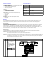
Mode
ON
OFF In this configuration, C1
uses Multibus power; C2
uses an external power
supply.
• Maximum combined
current for outputs 1 to
4 = 1A (according to
available Multibus
power)
• Maximum combined
current for outputs 5 to
8 = 2A
12Vdc
Multibus Power
Wiring Diagram
C1 C1
C2 C2
ON
OFF
-
+
24Vdc
Power Supply
24Vdc Relay
Imperial Multibus
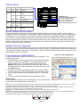
In this configuration, all
outputs use the C1 power
supply.
• Maximum combined
current for all 8 outputs
= 2A
0-24Vac/dc
External Power
C2 OFF
-
+
C2 STATE
+
C1 ON
BUS INPUT
0-24Vac/dc
External Power
OFF ON
C1 STATE
12Vdc Relay
C1 C1
C2 C2
OFF
ON
-
+
+
-
24Vdc
Power Supply
24Vdc Relay
C1 STATE
C1 OFF
C2 STATE
-
+
24Vdc Relay
C2 ON
BUS INPUT
Imperial Multibus
OFF OFF In this configuration, both
C1 and C2 terminals use
external power supplies.
• Maximum combined
current for outputs 1 to
4 = 2A
• Maximum combined
current for outputs 5 to
8 = 2A
0-24Vac/dc
External Power
C1 C1
C2 C2
OFF
OFF
+
+
24Vdc
Power Supply
-
24Vdc Relay
~
C2 STATE
~
C1 OFF
BUS INPUT
0-24Vac/dc
External Power
Imperial Multibus
C2 OFF
~
24Vac
Power Supply
24Vac Relay
~