1
Connection terminals:
FLXE 118/. 0 , FLXE 118/. 1:
- L1, L2, N, PE, S1,
2 x 4mm2 max. / clamp - solid, stranded
passtrough wireing is possible,
- clamp for external earthing
2 x 6mm2 max. - solid, stranded, tightening torque for screw clamp 2,2 Nm.
FLXE 118/. 2:
- clamps in EEx de adapter for connection L1, L2, N, PE, 2,5mm2 max. / clamp solid, stranded; tightening torque for clamp screw 1,2 Nm; EEx e cable gland M25 for
cables ¯v 6-15 mm; tightening torque for gland screw 2,5 Nm,
- clamp for external earthing
2 x 6mm2 max. - solid, stranded, tightening torque for screw clamp 2,2 Nm
Work mode:
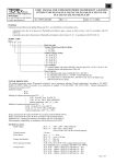
Network grid power supply – common lighting – Network connection have to be performed according to scheme on electronic module
- N, L1, L2, PE. Switch phase connection have to be performed through switch on L2 clamp. Phase connection for power supply of
electronic module have to be performed through N, L1, PE clamps.
Battery supply – emergency lighting – three types of connection are possible:
a) maintained (permanent, Dauerschaltung)
In case of network grid power supply failure, no matter of position of switch in L' circuit (network grid power supply is switched on
or off), luminaire is working in emergency mode. Network connection have to be performed according to scheme - N, L1, L2, PE.
Contacts S1 have to be connected with jumper bar on connection plug clamp in luminaire (performed by manufacturer).
b) permanent connection with possibility of disconnecting emergency lighting
Just like a) only that contacts S1 lead outside the lamp (remote switch). With switch is possible to turn on or off the emergency
lighting if network grid power supply occur.
c) non maintained (non permanent, Bereitschaftschaltung)
Luminaire doesn't work on network grid power supply, only with battery supply in case of network grid power supply failure.
Network connection have to be performed according to scheme - N, L1, PE – do not connect L2. Contacts S1 have to be connected
with jumper bar on connection plug clamp in luminaire (performed by manufacturer).
ELECTRONIC MODULE
NLE
S1
N
L1
L2
PE
N
L
L'
1
2
3
L
4
Selfcontrol of rightness emergency lighting
In time periods specified by manufacturer, when network grid power supply is present, electronic module automaticaly execute
selfcontrol of rightness functionality of emergency lighting and battery capacity.
Functionality test
Assumption for test
Continuance
Repetition period
Test signalization
Test object
Mulfunction signalization
Procedure when the tube is defected
Procedure when the battery is defected
Capacity test
1 hour of continues network grid
48 hours of continues network
power supply
grid power supply
1 minute
2 hours
7 days
364 days
LED-signal: test functionality / capacity
functionality of light source (tube mulfunction)
functionality of battery (battery mulfunction)
LED-signal: tube mulfunction / battery mulfunction
test is finished,
test is finished, will be repeated
it won't happen again
again when mulfunction is
eliminated
test is finished, it won't happen again
2