1
Operating Instructions
MEW01163
Revision -
Fire Alarm System EBL512 G3
V1.0.x
Author:
Jan Pettersson
Date of issue: 2010-04-27
Date of rev:
This page has deliberately been left blank.
Panasonic Electric Works Nordic AB
MEW01163
Rev: -
Operating Instructions Fire alarm system EBL512 G3, V1.0.x
Table of contents
1
2
Introduction________________________________ 5
Definitions / Explanations ____________________ 7
2.1
2.2
PEWN AB ________________________________________ 7
Alarm points ______________________________________ 7
2.2.1
Smoke detector ________________________________ 7
2.2.2
Sensor _______________________________________ 7
2.2.3
Analog detector ________________________________ 7
2.2.4
Analog (Sensor) Base (ASB) _____________________ 7
2.2.5
Conventional detector ___________________________ 7
2.2.6
(Conventional Detector) Base (CDB) _______________ 7
2.2.7
Addressable ___________________________________ 7
2.2.8
Conventional zone line input / External line __________ 8
2.3
Output unit _______________________________________ 8
2.4
Output / Control output ______________________________ 8
2.5
Short circuit isolator (ISO) ___________________________ 8
2.6
Display unit (DU) __________________________________ 8
2.7
COM loop ________________________________________ 8
2.8
Control Unit / C.U. / C.I.E. ___________________________ 8
2.9
Fire Brigade Panel (FBP) ____________________________ 8
2.10 Control panel (CP) _________________________________ 8
2.11 System ___________________________________________ 8
2.12 Network / TLON® / LonWorks® / Echelon / Node / TLON
Conn. board / Gateway / Sub net / Backbone net / Router / Repeater 9
2.13 LED _____________________________________________ 9
2.14 External Indicator (LED) ____________________________ 9
2.15 Display / LCD _____________________________________ 9
2.16 Door open (Door / Key switch) ________________________ 9
2.17 Site Specific Data (SSD) _____________________________ 9
2.18 Software (S/W) / System program ____________________ 10
3
Overview _________________________________ 11
3.1
The EBL512 G3 system ____________________________ 11
3.1.1
Printer ______________________________________ 11
3.1.2
Expansion boards _____________________________ 11
3.1.3
Power supply _________________________________ 11
3.2
S/W versions _____________________________________ 12
3.3
Documents ______________________________________ 12
3.4
Applications _____________________________________ 12
3.5
PC S/W _________________________________________ 12
4
5
6
Control Unit ______________________________ 13
LED indicators and push buttons _____________ 15
The display (LCD) _________________________ 19
1
Panasonic Electric Works Nordic AB
MEW01163
Rev: -
6.1
6.2
6.3
6.4
Operating Instructions Fire alarm system EBL512 G3, V1.0.x
Areas in the display ________________________________ 19
The symbol area __________________________________ 19
The information area priority order ____________________ 20
System information in the LCD ______________________ 21
6.4.1
User definable system information ________________ 21
7
Access levels _______________________________ 22
7.1
7.2
7.3
7.4
7.5
7.6
Access level 1 ____________________________________ 23
Access level 2A ___________________________________ 23
Access level 2B ___________________________________ 24
Access level 3A ___________________________________ 25
Access level 3B ___________________________________ 25
Access level 4 ____________________________________ 25
8
"Silence Alarm devices"_____________________
9
Disable / Re-enable alarm devices _____________
10
"Silence buzzer" ___________________________
11
Disable / Re-enable all control, extinguishing and
ventilation outputs _______________________________
12
Evacuate__________________________________
13
Open door ________________________________
26
27
28
29
30
31
13.1
Outputs for routing equipment (Fire brigade tx and Fault tx) 31
14
Technical number / Presentation number ______ 32
14.1
14.2
Technical number for COM loop units _________________ 32
Presentation number _______________________________ 33
15
Alarm types _______________________________ 34
15.1 Pre-warning ______________________________________ 34
15.2 Fire alarm _______________________________________ 35
15.2.1 Enter the menu during fire alarm _________________ 38
15.3 Heavy smoke alarm / Heavy heat alarm ________________ 39
15.4 Alert Annunciation alarm (AA alarm) _________________ 40
15.5 Key cabinet alarm _________________________________ 41
15.5.1 Key cabinet opened before a fire alarm_____________ 41
15.5.2 Key cabinet opened in conjunction with a fire alarm __ 41
15.6 Co-incidence alarm (2-address / -zone dependence) _______ 42
15.7 Quiet alarm ______________________________________ 43
16
Alarm reset _______________________________ 44
16.1 Pre-warning reset _________________________________ 44
16.2 Fire alarm reset ___________________________________ 44
16.2.1 All _________________________________________ 44
16.2.2 Single_______________________________________ 44
16.2.3 Single with automatic disablement ________________ 45
16.3 Heavy smoke / heat alarm reset ______________________ 45
16.4 Alert Annunciation ________________________________ 45
16.5 Key cabinet alarm reset _____________________________ 45
2
Panasonic Electric Works Nordic AB
MEW01163
Rev: -
Operating Instructions Fire alarm system EBL512 G3, V1.0.x
16.6
16.7
Co-incidence alarm ________________________________ 46
Quiet alarm reset __________________________________ 46
17
Fault _____________________________________ 47
17.1
17.2
Fault messages ___________________________________ 48
Fault acknowledge ________________________________ 63
18
Commissioning an installation _______________ 65
18.1 Single Control Unit ________________________________ 65
18.2 Control Units in a TLON network ____________________ 65
18.2.1 TLON network installation ______________________ 66
18.3 Add a Control Unit in a TLON network ________________ 67
18.4 Make two TLON networks one. ______________________ 67
18.5 Delete a Control Unit in a TLON network ______________ 67
19
Programming (SSD download) _______________ 68
19.1
19.2
19.3
19.4
Check All Loop Units ______________________________ 68
Single Control Unit ________________________________ 68
Control Units in a TLON network ____________________ 69
User definable text messages download ________________ 69
20
New system program (S/W) version download __ 70
20.1
20.2
Single control unit (c.i.e.) ___________________________ 70
Control Units in a TLON network ____________________ 72
21
Upgrade number of alarm points _____________ 73
21.1
Control Units in a TLON network ____________________ 73
22
23
24
25
Restart ___________________________________
Access ____________________________________
Perform monthly test (H1) ___________________
Disable or re-enable (H2) ____________________
74
78
80
83
25.1 Disable zone (H2/B1) ______________________________ 84
25.2 Disable zone / address (H2/B2) _______________________ 85
25.3 Disable output (H2/B3) _____________________________ 87
Re-enable zone (H2/B4) __________________________________ 88
25.4 Re-enable zone / address (H2/B5) _____________________ 89
25.5 Re-enable output (H2/B6) ___________________________ 90
25.6 Disable / re-enable output type (H2/B7) ________________ 92
25.7 Disable / re-enable alarm devices (H2/B8) ______________ 94
25.8 Disable / re-enable routing equipment (H2/B9) __________ 96
25.9 De-activate Alert Annunciation function (H2/B10) _______ 97
26
27
Set calendar and clock (H3) __________________ 98
Present system status (H4) ___________________ 99
27.1 Disablement (H4/U1) ______________________________ 99
27.2 Disablement by time channel (H4/U2) ________________ 100
27.3 Open doors (H4/U3) ______________________________ 101
27.4 Sensor values (H4/U4) ____________________________ 102
27.4.1 Reset of a week average sensor value _____________ 103
3
Panasonic Electric Works Nordic AB
MEW01163
Rev: -
Operating Instructions Fire alarm system EBL512 G3, V1.0.x
27.5
27.6
27.7
Sensors activating SERVICE signal (H4/U5) ___________ 105
Event log (H4/U6) ________________________________ 105
Show information (H4/U7) _________________________ 106
28
Service (H5) ______________________________ 109
28.1
28.2
28.3
28.4
28.5
28.6
28.7
28.8
Access code for service / maintenance (H5 and H8)______ 110
Calibration of supervised outputs (H5/A1) _____________ 111
Sensitive fault detection mode (H5/A2) _______________ 112
Service mode for COM-loop (H5/A3) ________________ 113
Display current consumption in unit (H5/A4)___________ 115
Display current consumption COM-loop (H5/A5) _______ 116
Display statistics for communication (H5/A6) __________ 117
Activate address setting mode for DU (H5/A7) _________ 119
29
30
31
FAULT Acknowledge (H6) _________________ 120
Perform ZONE TEST (Test mode) (H7) ______ 121
Maintenance (H8) _________________________ 123
31.1
31.2
31.3
31.4
31.5
31.6
31.7
31.8
31.9
31.10
31.11
Access code for service / maintenance ________________ 123
Disconnect loop (H8/S1) ___________________________ 123
Re-connect loop (H8/S2)___________________________ 125
Acknowledge SERVICE signal (H8/S3)_______________ 126
Clear weekly average (H8/S4) ______________________ 128
Test of alarm devices (H8/S5) _______________________ 129
Safe shut down of control unit (H8/S6) _______________ 131
Activate address in alarm mode (H8/S7) ______________ 133
Synchronize the control units (H8/S8) ________________ 135
Change code for service / maintenance (H8/S9) _______ 137
Change code for PC-communication (H8/S10) _______ 138
32
Interlocking outputs and inputs (H9) _________ 139
32.1
32.2
32.3
32.4
32.5
Activated interlocking outputs / inputs (H9/C1) _________ 139
Activate interlocking output (H9/C2) _________________ 140
Reset interlocking output (H9/C3) ___________________ 141
Disable interlocking output (H9/C4) __________________ 142
Re-enable interlocking output (H9/C5) ________________ 143
33
Change access code for daily duties (H10) _____ 144
34
Annual control ___________________________ 145
35
How to change paper in the printer __________ 146
36
Replacing a TLON connection board and/or the
Main board____________________________________ 147
37
Battery maintenance _______________________ 148
38
How to avoid unnecessary (nuisance) fire alarms 149
39
Information regarding radioactive radiation source151
40
Revision history ___________________________ 152
4
Panasonic Electric Works Nordic AB
MEW01163
Rev: -
1
Operating Instructions Fire alarm system EBL512 G3, V1.0.x
Introduction
EBL512 G3 Operating Instructions is a document intended to be used
by the end-user and the fire brigade personnel as well as service /
commissioning engineers.
Due to continual development and improvement, different S/W
versions are to be found. This document is valid for S/W version
1.0.x. On the date / rev date of this document x = 0.
Since the EBL512 G3 control unit (c.i.e.) is produced for many
countries the look, the texts, the functions, etc. might vary.
Products
Consists of one or more parts (HW) according to a Product Parts
List. A product has:
a type number
5000 EBL512 G3 c.i.e. Configured for 128, 256 or 512 alarm
points and with or without printer depending on article number.
5001 EBL512 G3 c.i.e. No front panel and no Plexiglas in the
door. Configured for 128, 256 or 512 alarm points depending
on the article number.
an article number is often the same as the type no. but a country
code can be added (e.g. SE for Sweden). If the letters PRT also
are added in the article number the product comes with a printer.
If digits are added to the article number they are showing the
number of alarm points configured (e.g. 5000PRTSE-128).
a product name (e.g. EBL512 G3 CU, 128 alarm points, with
printer)
HW
A HW (e.g. a printed circuit board) has:
a type number (e.g. 5010)
an article number, often = the type no. and sometimes is a
country code added (e.g. 5010SE)
a product name (e.g. Main Board 128 alarm points)
a p.c.b. number (e.g. 9290-3B) and can also have a configuration
(e.g. CFG: 2) and a revision (e.g. REV: 2)
sometimes a S/W
S/W
A S/W has:
a version number (e.g. V1.0.x)
5
Panasonic Electric Works Nordic AB
MEW01163
Rev: -
Operating Instructions Fire alarm system EBL512 G3, V1.0.x
sometimes additional information, such as Convention (different
functions / facilities), Language, Number of addresses, etc.
PC S/W
A PC S/W is a program used for programming, commissioning, etc. It
has a version number.
6
Panasonic Electric Works Nordic AB
MEW01163
Rev: -
2
Operating Instructions Fire alarm system EBL512 G3, V1.0.x
Definitions / Explanations
Definitions / explanations / abbreviations / etc. frequently used or not
explained elsewhere in the document.
2.1
PEWN AB
Panasonic Electric Works Nordic AB
2.2
Alarm points
Units, which can generate a fire alarm (in the control unit), i.e. analog
detectors (sensors), conventional detectors, manual call points, etc.
2.2.1
Smoke detector
Analog and conventional photoelectric (optical) smoke detectors are
available.
2.2.2
Sensor
Sensor = Analog detector
2.2.3
Analog detector
Contains an A/D-converter. The Control Unit pick up the digital
values ("sensor values") for each detector individually.
All
evaluations and "decisions" are then made in the c.i.e. Analog
detectors are addressable – an address setting tool is used for detector
types 33xx / 430x.
An analog detector has to be plugged in an analog sensor base (ASB).
2.2.4
Analog (Sensor) Base (ASB)
A sensor is plugged in an ASB, which is connected to a COM loop
(see below).
2.2.5
Conventional detector
Detector with only two statuses, i.e. normal and fire alarm. The
detector contains a closing contact and a series alarm resistor.
Normally plugged in a conventional detector base CDB (see below)
connected to a conventional zone line input, with an end-of-line
device. Some types are connected directly on zone line.
2.2.6
(Conventional Detector) Base (CDB)
A conventional detector is plugged in a CDB, connected to a
conventional zone line input.
2.2.7
Addressable
A unit with a built-in address device, i.e. each unit is individually
identified, handled and indicated in the c.i.e.
(The unit can be an I/O unit with a zone line input, to which one or
more conventional "alarm points" can be connected.)
7
Panasonic Electric Works Nordic AB
MEW01163
Rev: -
2.2.8
Operating Instructions Fire alarm system EBL512 G3, V1.0.x
Conventional zone line input / External line
Input intended for one or more conventional alarm points. End-of-line
device in the last alarm point.
2.3
Output unit
Addressable unit with programmable control outputs. Connected to a
COM loop (see below).
2.4
Output / Control output
Defined or programmable function. Relay output or voltage output
(supervised / monitored), in the c.i.e. or an output unit.
2.5
Short circuit isolator (ISO)
Addressable unit for automatic disconnection of a part (segment) of a
COM loop (see below) in case of a short circuit on the loop.
(According to EN54-2: One ISO is required per 32 alarm points on
the COM loop.)
2.6
Display unit (DU)
Addressable unit for fire alarm presentation (incl. user definable text
messages, if programmed).
2.7
COM loop
Loop = a cable, with two wires, to which all the addressable units can
be connected. Starts in the c.i.e. and it returns back to the c.i.e.
2.8
Control Unit / C.U. / C.I.E.
Control Unit = Control and Indicating Equipment = Unit to which the
alarm points are connected (via a COM loop). Indicates fire alarm,
fault condition, etc. Fire Brigade Panel & Control Panel (see below)
included or not included. Printer included or not included.
2.9
Fire Brigade Panel (FBP)
Unit intended for fire alarm presentation, etc. for the fire brigade
personnel. Can be a part of the control unit (front) or a separate unit
(external FBP).
In the ext. FBP, a printer can be included or not included.
2.10
Control panel (CP)
A part of the control unit (front), intended for the building occupier,
service personnel, etc., to "communicate" with the control unit /
system.
2.11
System
Several control units connected via a TLON network (co-operating
control units).
8
Panasonic Electric Works Nordic AB
MEW01163
Rev: -
2.12
Operating Instructions Fire alarm system EBL512 G3, V1.0.x
Network / TLON® / LonWorks® / Echelon /
Node / TLON Conn. board / Gateway / Sub
net / Backbone net / Router / Repeater
Brief explanations to the words/expressions to be found in connection
with a "network". See also separate TLON Technical description.
TLON® = TeleLarm Local Operating Network = a LonWorks®- based
network for communication between several units/nodes. The
protocol is LonTalk and the transmission works with doublyterminated bus topology (Echelon FTT-10). To connect a control unit
to the network, a TLON connection board is plugged in the control
unit. (Old installations: Some control units, not prepared for network
connection, could be connected via a serial interface and a Gateway).
A network can be one sub net (FTT-10) or several sub nets, connected
via routers. (In the TLON Network a sub net = a channel.)
Routers are also used to increase the maximum cable length, node to
node, in a network.
All network programming (configuration) are made with the PC
program "TLON Manager".
2.13
LED
LED (Light Emitting Diode) = Yellow, green or red optical indicator
("lamp").
2.14
External Indicator (LED)
A unit with an LED. Connected to an ASB, CDB or a detector with a
built-in LED. Old installations: Also connected to an ADB.
Lit when the built-in LED is lit.
2.15
Display / LCD
LCD (Liquid Crystal Display) = Display (in the c.i.e. or Display unit)
for presentation of fire alarms, fault messages, etc. a graphical
monochrome LCD (320 x 240 dots) and backlight.
2.16
Door open (Door / Key switch)
In EBL512 G3 there is a door switch, which is activated when the
control unit door is open. In some other units this door switch is
replaced with a key switch.
When the door is open a message "Door is open in this unit" is shown
in the LCD.
2.17
Site Specific Data (SSD)
The SSD is unique for each installation.
All alarm points,
presentation numbers, user definable text messages, programmable
outputs, etc. are created in the PC program WinG3 and also
downloaded in EBL512 G3 with WinG3.
9
Panasonic Electric Works Nordic AB
MEW01163
Rev: -
2.18
Operating Instructions Fire alarm system EBL512 G3, V1.0.x
Software (S/W) / System program
The S/W makes the control unit (the microprocessor) work. It is
factory downloaded but a new version can be downloaded in EBL512
G3 on site.
10
Panasonic Electric Works Nordic AB
MEW01163
Rev: -
Operating Instructions Fire alarm system EBL512 G3, V1.0.x
3
Overview
3.1
The EBL512 G3 system
EBL512 G3 is a microprocessor controlled intelligent fire alarm
system, intended for analog addressable smoke detectors, as well as
conventional detectors and manual call points. Programmable control
outputs and output units are available. Up to 1020 addresses (of
which up to 512 can be alarm points) can be connected to each control
unit (c.i.e.).
EBL512 G3 is available in several types, versions and configurations.
It can be connected to a TLON network, a "system", with up to 30
control units. Each control unit has access to all information.
Product type no. Product name
5000
EBL512 G3 c.i.e. with front and display
5001
EBL512 G3 c.i.e. without front and display
EBL512 G3 is designed according to the European standard EN54,
part 2 and 4. The Swedish front conforms to SS3654.
3.1.1
Printer
The control unit EBL512 G3 type 5000 (with "PRN" included in the
article number) comes with a printer. (The printer type number as a
spare part is 5058.)
In Ext. Fire Brigade Panel 1826 it is possible to mount an optional
Printer 1535.
3.1.2
Expansion boards
In the control unit (c.i.e.) it is possible to mount up to six expansion
boards. The following types are available:
Product type no.
4580
4581
4583
Product name
Note
8 zones expansion board
8 relay outputs expansion board
Multipurpose I/O expansion board
Regarding the expansion boards, see also the EBL512 G3 Planning
Instructions and drawings.
3.1.3
Power supply
The main power source is a built-in rectifier (5037), 230 V AC / 24 V
DC, 6.5 A.
The second power source is a backup battery (2 x 12 V). In the c.i.e.
is space for two 27 Ah batteries. Larger batteries (up to 65 Ah) have
to be placed outside the c.i.e.
The batteries and the rectifier are connected to the Main board (5010),
which handles the charging of the batteries, etc. See the EBL512 G3
Planning Instructions, chapter "Power supply" for more information.
11
Panasonic Electric Works Nordic AB
MEW01163
Rev: -
3.2
Operating Instructions Fire alarm system EBL512 G3, V1.0.x
S/W versions
Due to continual development and improvement, different S/W
versions can be found. When installing a new control unit in a system
with "older" control units, you might have to update the S/W in the
old control units. The same S/W version is required in all control
units.
3.3
Documents
The following documents (except this document) are available:
Planning instructions
Drawings
Normally information found in one document is not to be found in
another document, i.e. the documents complement each other.
3.4
Applications
The EBL512 G3 system is intended for small, medium and large
installations. The intelligent control units offer the system designer
and end user a technically sophisticated range of facilities and
functions. Programming (PC S/W WinG3 and TLON Manager) and
commissioning of the control unit / system is very easy. Start with
one control unit and then, when required, add more units. The TLON
network makes it possible to install the control units in one building or
in many buildings.
3.5
PC S/W
WinG3 is used for programming and commissioning of one or more
control units:
create / download / backup (upload) of site specific data (SSD)
download of S/W / settings / conventions / configurations / C.U.
& system properties / etc.
create / download the user definable text messages (alarm texts)
shown in the display in the C.U. and ext. FBP / Display units.
WinG3 shall have the same (or higher) version number as the EBL512
G3 S/W version number (e.g. 1.0.x and 1.0.x respectively). Backup
require the same version number (in WinG3 and in EBL512 G3). Old
files can be opened and saved in a newer version of WinG3 and
thereafter downloaded.
TLON Manager is used for the network programming.
12
Panasonic Electric Works Nordic AB
MEW01163
Rev: -
4
Operating Instructions Fire alarm system EBL512 G3, V1.0.x
Control Unit
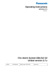
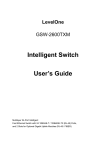
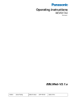
Figure 1. EBL512 G3 Control Unit 5000 with printer. The look
might vary according to configuration, country, etc.
Depending on country, convention, configuration, etc. the look,
language and functions might vary. Figure 1 shows an EBL512 G3
with an English front. EBL512 G3 is housed in a grey metal cabinet.
The door has a Plexiglas ahead of the front and display, see Figure 1.
A key is required to open the door to get full access to the push
buttons on the front, i.e. the Fire Brigade Panel (FBP) and the Control
Panel (CP).
13
Panasonic Electric Works Nordic AB
MEW01163
Rev: -
Operating Instructions Fire alarm system EBL512 G3, V1.0.x
L1
L2
P1
L3
P2
L4
L5
L6
P3
P4 – P7
P8
L7, L8
L9, L10
L11, L12
L13, L14
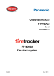
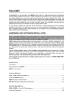
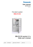
Figure 2. The EBL512 G3 front with display; FBP (upper part)
and CP (lower part). The look might vary according to
language. (An English front is shown in the figure). See also
chapter "LED indicators and push buttons", page 15.
The fire brigade personnel use the FBP to see which alarm point /
zone(s) having activated fire alarm and to take required operational
control of the system. In the graphical display, the information in the
upper part is depending on how many alarm points / zones having
generated fire alarm. In the middle part a user definable text message
(alarm text) is shown for each alarm point / zone in alarm - if
programmed.
The CP is to "communicate" with the system, i.e. for commissioning,
monthly tests, maintenance, etc. Access codes for different access
levels are required. A keypad is used to get access to the system (a
menu tree with main and sub menus) and for different manoeuvres.
The CP has several LEDs for system status.
14
Panasonic Electric Works Nordic AB
MEW01163
Rev: -
5
Operating Instructions Fire alarm system EBL512 G3, V1.0.x
LED indicators and push buttons
LEDs and push buttons can vary according to type and configuration
(convention / country / language).
See also Figure 2, page 14.
LED indicators on the Fire Brigade Panel (FBP)
LED indicator
Indicating
L1
Fire (5 red)
Fire alarms (see below)
Co-incidence alarm
Pre-warning
Quiet alarm (normally Australia only)
Alarm Acknowledgement Facility (AAF) alarm (Australia
only)
See also chapter "Alarm types", page 34.
L2
Extinguishing (red)
Output(s) for extinguishing equipment activated. (Or a
programmable input type "Extinguishing" is activated.)
L3
Ventilation (yellow)
Output(s) for fire/smoke ventilation equipment activated. (Or
a programmable input type "Ventilation" is activated.)
L4
Fire brigade tx (red)
Output "Fire alarm" for fire brigade tx (routing equipment)
and/or corresponding programmable output(s) of type
"Routing equipment") is/are activated. (Or a programmable
input type "Fire brigade tx" is activated.)
Test of routing equipment in progress (see menu H1).
L5
Operation (green)
The c.i.e. is powered via the rectifier and/or the battery.
L6
Alarms queued (2 red)
More than one unit / zone have activated fire alarm. Use
push button "Alarms queued" (P8) to scroll amongst the
alarm points or soft key "Next zone" (P5) to scroll amongst
the zones.
NOTE! Fire alarms are:
Fire alarm (incl. test mode alarm)
Heavy smoke/heat alarm
Alert Annunciation (AA) alarm
Key cabinet alarm
15
Panasonic Electric Works Nordic AB
MEW01163
Rev: -
Operating Instructions Fire alarm system EBL512 G3, V1.0.x
Push buttons on the Fire Brigade Panel (FBP)
Push button
Operation/function
P1
Silence buzzer (yellow)
Used to silence the buzzer in the c.i.e.
P2
Silence Alarm devices
(red)
Used to silence alarm devices / sounders (i.e. outputs for
alarm devices will be de-activated).
P3
Reset (green)
Used to reset:
Fire alarms (see below)
Co-incidence alarms (if not automatically reset)
For more information see "Alarm reset", page 44.
NOTE! P3 has to be pressed for > 0.5 sec.
P4 – P7
Soft keys (grey)
The operation/function is shown above the key in the display
(i.e. the soft key area). The function of a soft key may vary
depending on the situation. If nothing is shown above the
key in the display, the key has no function for the moment.
P8
Alarms queued (grey)
Used when LEDs "Alarms queued" (L6) are lit, to
scroll/browse through the queued alarm points. Function, see
chapter "Fire alarm", page 35, under LEDs "Alarms
queued".
NOTE! Fire alarms are:
Fire alarm (incl. heavy smoke/heat alarm)
Alert Annunciation (AA) alarm
Key cabinet alarm
16
Panasonic Electric Works Nordic AB
MEW01163
Rev: -
Operating Instructions Fire alarm system EBL512 G3, V1.0.x
LED indicators on the Control Panel (CP)
LED indicator
Indicating
L7
System fault (yellow)
EBL512 G3 is not running because of S/W, CPU or
memory fault.
L8
Test mode (yellow)
One or more zones are in "test mode", see page 80 and
121.
Fault / Disablements
L9
General fault (yellow)
Fault(s) in the system, i.e. not acknowledged fault(s)
and/or not corrected fault(s). See also page 120.
L10
General disablements
(yellow)
Disablement(s) in the system.
Also valid for "Single encapsulated reset", see page 45.
L11
Alarm devices (yellow)
Steady / cont.: Output(s) type "Alarm device" are
disabled.
Blinking: One or more supervised outputs type
"Alarm device" have generated fault(s).
This is also valid when the c.i.e. has no "contact" with
a unit with such an output, e.g. 3377, 3379, 3364, etc.
L12
Fire brigade tx (yellow)
Steady / cont.: Output(s) for "Routing equipment"
disabled via menu (H2/B3 or B9) or via open door.
Blinking: Routing equipment power supply output1 or
one or more supervised outputs (of type "Routing
equipment" have generated fault(s). This is also valid
when the c.i.e. has no "contact" with a unit with such
an output, e.g. 3361, etc.
Routing equipment
L13
Fault tx activated (yellow)
One or more not acknowledged faults. Output "Fault
condition" for fault tx (routing equipment) is activated.
Test of routing equipment in progress (see menu H1).
Sensitive fault detection mode (see menu H5/A2) is on.
L14
Fire brigade tx delay
(yellow)
1
The Alert Annunciation function is enabled, i.e. time
channel controlling this function is "on". The AA
function is described in the EBL512 G3 Planning
Instructions, chapter "Alert Annunciation". LED
"L14" will be "on" if the AA function is enabled for at
least one alarm point / zone. Normally is only one
time channel used for this function but two or more
channels can be used. The AA function can, as an
alternative, be continuously "on".
Main board 5010 term. block "J3:3-4", fuse F8 (T500mA L 250 V – TR5).
17
Panasonic Electric Works Nordic AB
MEW01163
Rev: -
Operating Instructions Fire alarm system EBL512 G3, V1.0.x
Push buttons / Keypad on the Control Panel (CP)
Key/push button
Operation/function
↵ (Enter)
Used to log on, i.e. to get access to the menu tree (via an access
code) and to accept a menu and accept input of data.
◄►▲▼
Left / right keys are used to move the cursor in a menu.
Up / down keys are used to scroll between the menus.
1 – 9 and 0
Numeric keys for the figures 0-9.
DEL
Used to clear /delete just written data.
ESC
Used to stop input of data, leave a menu ("one step up") and to
log off.
18
Panasonic Electric Works Nordic AB
MEW01163
Rev: -
Operating Instructions Fire alarm system EBL512 G3, V1.0.x
6
The display (LCD)
6.1
Areas in the display
Symbol area
Information area
Soft key area
Menu
Next zone
Re-enable
Evacuate
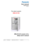
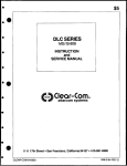
The display is divided in three areas:
The symbol area: Some events are indicated with symbols, see 6.2
below.
The information area: General area for all kind of information
and the menu system.
The soft key area: The function of a soft key is shown in this area.
The function of a soft key may vary depending on the situation.
If nothing is shown, the soft key has no function for the
moment.
6.2
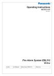
The symbol area
The symbol area is at the top of the display, see 6.1 above.
The symbol area
Symbol
Indicating
Door open.
Any c.i.e. door in the system is opened. See also page 31.
Also valid for ext. FBPs.
Loss of mains.
Any c.i.e. or ext. power supply in the system is out of 230 V AC.
The week average sensor value is over the service level for one or
more analog smoke detectors in the system. See also page 105.
Note that the symbol area may be suppressed see 6.3.
19
Panasonic Electric Works Nordic AB
MEW01163
Rev: -
6.3
Operating Instructions Fire alarm system EBL512 G3, V1.0.x
The information area priority order
When the control unit / system is in normal operation (quiescent
state), i.e. no fire alarms, no faults, no disablements, no service
signals, no zones in test mode, no activated interlocking in / outputs,
and/or Alert Annunciation function not enabled, only the LED
"Operation" (L5) should be lit and some system information is
shown in the control unit display. However, the system information
has the lowest priority and more important information suppresses less
important. In some cases also valid for the symbol area.
The priority order is:
Priority
Event
Symbol area
is visible
1
Fire alarms (see below)
No
2
Co-incidence alarm
No
3
Pre-warning
No
4
Quiet alarm
No
5
2
AAF alarm
Yes
3
6
Evacuate information
Yes
7
Fault (not acknowledged)
Yes
8
Disablement
Yes
9
Zones in Test mode
Yes
10
Interlocking input / output active
Yes
11
SERVICE signal
Yes
12
System information
Yes
NOTE! Fire alarms are:
Fire alarm
Heavy smoke/heat alarm
Alert Annunciation (AA) alarm
Key cabinet alarm
The different type of events and the menu system are described in
other parts of this document. Regarding "System information", see
6.4.
2
The AAF function is used in conjunction with an AAF Control, which is
available on the Australian market only.
3
Only valid for Belgian, British Standard, Hungarian, Spanish and
Ukrainian conventions.
20
Panasonic Electric Works Nordic AB
MEW01163
Rev: -
6.4
Operating Instructions Fire alarm system EBL512 G3, V1.0.x
System information in the LCD
EBL512 G3, control unit number, date and time are displayed. The
exact look is convention / language dependent.
One example:
EBL512 G3
Control Unit: XX
yyyy-mm-dd hh:mm
yyyy-mm-dd = (Date) Year-Month-Day
Control Unit; XX = 00-29
hh:mm = (Time) hour:minute
6.4.1
User definable system information
User definable system / installation information (created and
downloaded via WinG3) can be displayed in the middle of the display.
Two rows à 40 characters are available. This information is shown in
all control units in the system.
One example:
EBL512 G3
Control Unit: XX
Panasonic Electric Works
Fire & Security Technology Europe AB
yyyy-mm-dd hh:mm
21
Panasonic Electric Works Nordic AB
MEW01163
Rev: -
7
Operating Instructions Fire alarm system EBL512 G3, V1.0.x
Access levels
EBL512 G3 has different access levels (1-4) for different kind of
users. Access levels 2 and 3 are divided in sub levels (A-B).
Access
level
Access code
(password)
Required action
Users
1
N/A
None
(Door closed).4
Anybody.
Scroll / browse
through the queued
alarms.
2A
N/A
Fire brigade key.
Fire brigade
personnel.
Fire alarm handling.
2B
****
Fire brigade key +
Building
access code for level occupier /
2B (or 3A).
installation
owner.5
Installation handling
(daily duties), e.g.
monthly tests, disablements, etc.
3A
****
Fire brigade key +
Service /
access code for level maintenance
3A.
personnel.
Service,
maintenance,
commissioning, etc.
3B
********
PC (WinG3)
connected + PC
access code for level
3B.
Service,
maintenance,
commissioning, etc.
via WinG3.
4
********
PC (WinG3)
Manufacturer.
connected + PC
access code for level
3B and level 4.
Service /
maintenance /
commissioning
engineer.
Action
Changing factory
settings.
The access codes can be changed. To change a code you have to use
the valid code or use a code for a higher access level.
Retailers are informed regarding the default access code respectively.
4
The c.i.e. door is closed but the Plexiglas in the door is provided with a
hole for access to the "Alarms queued" button (P8), see Figure 1, page 14.
5
Normally a person on site, trained in order to perform monthly tests, disablements, etc.
22
Panasonic Electric Works Nordic AB
MEW01163
Rev: -
7.1
Operating Instructions Fire alarm system EBL512 G3, V1.0.x
Access level 1
With the door closed4, anybody has access to the push button "Alarms
queued" (P8) to scroll / browse through the queued alarms.
7.2
Access level 2A
After the door has been opened ("Door open" symbol
in the
symbol field), the user / fire brigade personnel have access to the
push buttons / keypad to do the following:
Push
button
Operation/function
P1
Silence the buzzer in the c.i.e.
P2
Silence all alarm devices (sounders).
P3
Reset fire alarms. (see below)
NOTE! Fire alarms are:
Fire alarm (incl. heavy smoke/heat alarm)
Alert Annunciation (AA) alarm
Key cabinet alarm
Co-incidence alarm (if not reset automatically)
23
Panasonic Electric Works Nordic AB
MEW01163
Rev: -
7.3
Operating Instructions Fire alarm system EBL512 G3, V1.0.x
Access level 2B
After the door has been opened ("Door open" symbol
in the
symbol field), the building occupier has access to level 2A and after
access code for level 2B (or 3A), access to the following menus:
H1 Perform monthly test
H2 Disable or re-enable
B1 Disable zone
B2 Disable zone / address
B3 Disable output
B4 Re-enable zone
B5 Re-enable zone / address
B6 Re-enable output
B7 Disable / re-enable output type
B8 Disable / re-enable alarm devices
B9 Disable / re-enable routing equipment
B10 De-activate alert annunciation function
H3 Set calendar and clock
H4 Present system status
U1 Disablement
U2 Disablement by time channel
U3 Open doors
U4 Sensor values
U5 Sensors activating SERVICE signal
U6 Event log
U7 Information
H6 FAULT acknowledge
H7 Perform zone test (Test mode)
H9 Interlocking outputs and inputs
C1 Activated interlocking outputs/inputs
C2 Activate interlocking output
C3 Reset interlocking output
C4 Disable interlocking output
C5 Re-enable interlocking output
H10 Change access code for daily duties
24
Panasonic Electric Works Nordic AB
MEW01163
Rev: -
7.4
Operating Instructions Fire alarm system EBL512 G3, V1.0.x
Access level 3A
After the door has been opened ("Door open" symbol
in the
symbol field), the service / maintenance personnel have access to
level 2A and after access code for level 3A, access to the following
menus:
Same menus as in access level 2B plus the following:
H5 Service
A1 Calibration of supervised outputs
A2 Sensitive fault detection mode
A3 Service mode for COM-loop
A4 Display current consumption in CU
A5 Display current consumption on COM-loop
A6 Display statistics for communication
A7 Activate address setting mode for DU
H8 Maintenance
S1 Disconnect loop / zone line input
S2 Re-connect loop / zone line input
S3 Acknowledge SERVICE signal
S4 Clear weekly average
S5 Test of alarm devices
S6 Safe shut down of control unit
S7 Activate address in alarm mode
S8 Synchronize the control units
S9 Change code for service / maintenance
S10 Change code for PC-communication
7.5
Access level 3B
Used by Service / maintenance / commissioning engineers when a PC
(i.e. WinG3) is to be connected to EBL512 G3 for backup (upload),
download of site specific data and/or download of software.
7.6
Access level 4
Used by manufacturer or by personnel authorised by the manufacturer
when a PC is to be connected to the control unit, i.e. when WinG3 is
to be used for re-initialisation of the alarm counter, change software
configurations, on-line status checking, etc.
25
Panasonic Electric Works Nordic AB
MEW01163
Rev: -
8
Operating Instructions Fire alarm system EBL512 G3, V1.0.x
"Silence Alarm devices"
In the control unit front (the FBP part) there is a push button "Silence
alarm devices" (P2).
When the alarm devices are activated (sounding)6 and the push button
"Silence alarm devices" is pressed, the following will happen:
The activated outputs programmed for sounders (type
"Alarm devices", will be turned OFF (de-activated)7
If the push button "Silence alarm devices" is pressed again, the
sounders will automatically sound again.
In case of a new alarm (Fire alarm, Co-incidence alarm or Prewarning) the sounders will automatically sound again.
In WinG3, the function “Silence Switch Disables Alarm Devices” can
be selected. In this case the button "Silence alarm devices" (P2) will
have the same function as the menu “Disable / re-enable alarm devices
(H2/B8)”. See also chapter "Disable / Re-enable alarm devices", page
27.
6
E.g. during Fire alarm, Co-incidence alarm or Pre-warning, etc.
7
Including Addressable siren 3377 and Addressable sounder base 3379.
26
Panasonic Electric Works Nordic AB
MEW01163
Rev: -
9
Operating Instructions Fire alarm system EBL512 G3, V1.0.x
Disable / Re-enable alarm devices
The outputs7 programmed for sounders (type "Alarm devices") can via
menu H2/B8 be collective disabled for one, several or all control
units. This is indicated by LED Fault / Disablements "General
disablements" (L10) and "Alarm devices" (L11) are steady ON.
In case of a fire, the sounders will remain disabled, i.e. the alarm
devices will not sound.
They will remain disabled until they are re-enabled again via menu
H2/B8.
See also chapter "Disable / re-enable alarm devices (H2/B8)", page
94.
27
Panasonic Electric Works Nordic AB
MEW01163
Rev: -
10
Operating Instructions Fire alarm system EBL512 G3, V1.0.x
"Silence buzzer"
The buzzer in the control unit will sound for:
Fire alarm8 (0.4 / 0.4 sec.)
Co-incidence alarm (2-zone or 2-unit dependent fire alarm):
When only one zone or one zone / address (alarm point) is in
alarm status (0.8 / 5 sec.)
Pre-warning (0.8 / 5 sec.)
Quiet alarm (0.8 / 5 sec.)
Fault (continuous)
Disablements and Faults (1 sec. directly after the door to the c.i.e.
is closed.)
Activated interlocking input (0.8 / 0.8 sec.), if this option is
selected via WinG3.
Press "Silence buzzer" (P1) to silence the buzzer.
In case of a new alarm (pre-warning, co-incidence alarm, etc.) or if the
push button "Silence buzzer" is pressed again, the buzzer will
automatically sound again.
Silence buzzer by open door
In WinG3 can the function "Silence Buzzer by Door Switch" be
selected. The buzzer will then be turned off as long as the control unit
door is open. (This function is a violation to the EN54-2 standard.)
EBL512 G3 c.i.e. type no. 5001
This unit has no front and no built-in buzzer.
8
Incl. Heavy smoke/heat alarm, AA alarm, Key cabinet alarm and
Acknowledged alarm (New Zealand only).
28
Panasonic Electric Works Nordic AB
MEW01163
Rev: -
11
Operating Instructions Fire alarm system EBL512 G3, V1.0.x
Disable / Re-enable all control,
extinguishing and ventilation
outputs
All control outputs programmed as type:
Control (general)
Fire ventilation
Extinguishing system
… can via menu H2/B7 be collective disabled for one, several or all
control units. This is indicated by LED Fault / Disablements
"General disablements" (L10).
They will remain disabled until they are re-enabled again via menu
H2/B7.
See also chapter "Disable / re-enable output type (H2/B7)", page 92.
29
Panasonic Electric Works Nordic AB
MEW01163
Rev: -
12
Operating Instructions Fire alarm system EBL512 G3, V1.0.x
Evacuate
This function is only valid for the Belgian, British Standard,
Hungarian, Spanish and Ukrainian conventions.
When the soft key "Evacuate" (P7) is pressed9, all outputs7,
programmed for sounders (type "Alarm devices"), will be collective
turned ON (steady). This is indicated by the following information in
the alphanumeric display:
Evacuate in progress
The sounders will remain turned ON until they are turned OFF by
pressing the soft key "Evacuate off" (P7).10
NOTE 1! The alarm devices (sounders) will always be activated
steady (sound continuously) irrespective of the fact that the outputs
can be set to anything else for fire alarm (e.g. intermittent).
NOTE 2! The text “Menu” above the soft key (P4) is visible in the
display only if the door in the c.i.e. is open, while the text "Evacuate" /
"Evacuate off" above (P7) is always visible in the current conventions.
9
10
Alt. when a programmable input is activated. One input per c.i.e.
Alt. when the programmable input is de-activated.
30
Panasonic Electric Works Nordic AB
MEW01163
Rev: -
13
Operating Instructions Fire alarm system EBL512 G3, V1.0.x
Open door
A special key is used to open the control unit door to get access to the
front / system. The same type of key is also used to open the ext. FBP
door.
If any door in the system is open the following symbol is shown in the
display's symbol area:
See also chapter Open doors (H4/U3), page 101.
13.1
Outputs for routing equipment (Fire
brigade tx and Fault tx)
Via WinG3 the following can be programmed (default settings
shown):
Disable routing equipment by door switch
None: Open door in a C.U. or an ext. FBP will not disable the
output(s) for routing equipment (Fire brigade tx and fault tx).
Any control unit door: Open door in any C.U. will disable the
output(s) for routing equipment (Fire brigade tx and fault tx) in
all C.U:s.
Any door: Open door in any C.U. or any ext. FBP will disable
the output(s) for routing equipment (Fire brigade tx and fault tx)
in all C.U:s.
Disabled outputs for routing equipment are indicated by the LEDs
Fault / Disablements "General disablements" (L10) and "Fire brigade
tx" (L12) and listed in menu H4/U1.
31
Panasonic Electric Works Nordic AB
MEW01163
Rev: -
Operating Instructions Fire alarm system EBL512 G3, V1.0.x
14
Technical number / Presentation
number
14.1
Technical number for COM loop units
The technical number, NNNNNN, is used when programming all
units connected to the COM loops.
Technical number is also used to identify which unit has generated a
fault.
001 - 255
The address on the COM loop.
The addresses don't have to be in
sequence.
The connections on the COM loop
don't have to be in sequence.
The address is for each unit set with
the programming tool 3314
NOTE!
Totally 102011 COM loop addresses can be used for one control unit,
of which up to 512 COM loop addresses can be used for alarm
points.
A brand new detector is factory set to COM loop address 000.
Connected on the COM loop, the detector LEDs will start blinking
every second, indicating that a COM loop address (001 - 255) has to
be set before the detector will work.
11
Since address 000 cannot be used, in fact the total number of addresses
will be 4 x 255 = 1020
32
Panasonic Electric Works Nordic AB
MEW01163
Rev: -
14.2
Operating Instructions Fire alarm system EBL512 G3, V1.0.x
Presentation number
For each fire alarm point / input / zone, a presentation number,
NNN-NN, has to be programmed. The presentation number is shown
in the c.i.e. display and ext. FBP display12, to identify the point / zone
activating fire alarm. It is also used to disable / re-enable fire alarm
points / zones and as trigger conditions in control expressions to
activate programmable outputs.
Together with the presentation number, a user definable 40 characters
text message (alarm text) can be displayed (if programmed).
01 – 99 = The address within the zone.
00 = Only the zone number will be
displayed, e.g. used for conventional zone
line inputs.
NOTE! Zone numbers 001-999 can be used but not more than 512
alarm points and/or zones can be used per c.i.e.
This is in accordance with the EN54-2 standard.
12
Also in the Alert Annunciation Units and Presentation Units ("Display
Units").
The presentation number (or a user definable 40 characters text message) can
also be shown in the old type of display units connected to the COM loops.
33
Panasonic Electric Works Nordic AB
MEW01163
Rev: -
15
Operating Instructions Fire alarm system EBL512 G3, V1.0.x
Alarm types
In case of a fire, analog detectors (sensors), conventional smoke
and/or heat detectors, manual call points and programmable inputs can
activate fire alarm. If somebody illegally breaks into a key cabinet,
this will also activate a "fire alarm" (i.e. a key cabinet alarm).
A fire alarm could be an Alert Annunciation alarm, i.e. the
activation of the routing equipment (fire brigade tx) is delayed during
an acknowledgement time and an investigation time respectively.
The analog detectors can also activate two other types of "alarm", i.e.
Pre-warning and Heavy smoke alarm / Heavy heat alarm.
"Two unit dependent" addressable alarm points (normally only smoke
detectors) and "2-zone dependent" zones, can activate a Co-incidence
alarm.
Quiet alarm is normally used on the Australian market only, for fan
control.
In the Australian convention only, an Alarm Acknowledgement
Facility function can be used. During the Acknowledgement Period
and the Investigation Period respectively, there will only be an
indication in the c.i.e. display. Special hardware is required.
Regarding the different alarm types, etc., see the following chapters.
NOTE!
In the following chapters are all different alarm types described.
The figures in this document show the essential information and
might not look exactly as shown in the display.
15.1
Pre-warning
Activation of Pre-warning is an option that has to be enabled (via
WinG3) for the whole system.
An analog detector will generate a pre-warning for a lower alarm level
than the fire alarm level.13 Pre-warning can be used when an early
alarm and/or an early action is required (e.g. a "soft" computer shut
down). Normal alarm devices (output type "Alarm devices"), routing
equipment, etc. will not be activated.
In case of a pre-warning, the following happens:
The buzzer in the c.i.e. sounds 0.8 sec. each 5th sec. (0.8 / 5
sec.).
LEDs "Fire" (L1) are blinking (0.4 / 0.4 sec.).
13
See EBL512 G3 Planning Instructions. Any programmable input can also
be used to activate a pre-warning, e.g. for a High Sensitivity Smoke Detector
system.
34
Panasonic Electric Works Nordic AB
MEW01163
Rev: -
Operating Instructions Fire alarm system EBL512 G3, V1.0.x
Outputs programmed for pre-warning are activated.14
In the c.i.e. display, a presentation number (zone/address) is
shown (for the first pre-warning).
In the c.i.e. display, a user definable text message (= the
alarm text for fire alarm) is shown (if programmed).
Example; pre-warning zone 123, address 45 (within zone 123):
Pre-warning
Zone
Address
123-45
SMOKE
User definable alarm text for 123-45.
Menu
"SMOKE" after the presentation number is automatically added
depending on the type of alarm point (i.e. SMOKE, HEAT, MULTI or
MCP).
NOTE! The text "Menu" (P4) is visible in the display, only if the
door in the CU is open.
If more than one pre-warning is activated, the LEDs "Alarms queued"
(L6) are blinking and the pre-warnings will be automatically scrolled
(each five seconds).
Pre-warnings are automatically reset see chapter "Alarm reset", page
44.
15.2
Fire alarm
The system can handle up to 15360 fire alarms but only 512 fire
alarms can be shown in the c.i.e. display. If more than 512 fire alarms
are activated, no more fire alarms will be shown until one or more of
the 512 fire alarms are reset.
14
Outputs programmed for General pre-warning and outputs programmed
for the activated pre-warning(s).
35
Panasonic Electric Works Nordic AB
MEW01163
Rev: -
Operating Instructions Fire alarm system EBL512 G3, V1.0.x
See also chapter "The information area priority order", page 20. In
accordance with the EN54-2 standard, the following happens in case
of a fire alarm:
The buzzer in the c.i.e. sounds 0.4 sec. each 0.4th sec. (0.4 /
0.4 sec.).
LEDs "Fire" (L1) are blinking (0.4 / 0.4 sec.).
Output for routing equipment (Fire brigade tx) and outputs
type "Routing equipment" are activated.
Outputs for fire alarm are activated.15
In the c.i.e. display, a presentation number (zone/address) is
shown (for the first fire alarm).
In the c.i.e. display, a user definable text message (alarm
text) is shown (if programmed).
In the c.i.e. display, is also some additional information
presented.
One alarm point activating fire alarm.
Example; fire alarm zone 002, address 03 (within zone 002):
First alarm: 002-03
Alarm number 1 (of 1)
Zone
Address
002-03
SMOKE
User definable alarm text for 002-03.
Menu
"SMOKE" after the presentation number is automatically added
depending on the type of alarm point (i.e. SMOKE, HEAT, MULTI or
MCP).
15
Outputs programmed for General fire alarm and outputs programmed for
the activated fire alarm(s).
36
Panasonic Electric Works Nordic AB
MEW01163
Rev: -
Operating Instructions Fire alarm system EBL512 G3, V1.0.x
More than one alarm point activating fire alarm.
Example; fire alarm zone 002, address 03 (within zone 002) and nine
other fire alarms in four different zones:
First alarm: 002-03
Alarm number 1 (of 10)
Zone
Address
002-03
SMOKE
User definable alarm text for 002-03.
Latest alarm: 003-11
4 zones in alarm
Menu
Next zone
"SMOKE" after the presentation number is automatically added
depending on the type of alarm point (i.e. SMOKE, HEAT, MULTI or
MCP).
User definable alarm text For each alarm point can an individual
alarm text be shown (if programmed) or the default control unit alarm
text (if programmed). For each zone it is an individual alarm text (if
programmed). Up to 40 alphanumeric characters can be used.
Additional information
First alarm, Latest alarm, Alarm number and number of zones in
alarm.
LEDs "Alarms queued" (L6) blinking (0.4 / 0.4 sec.) are indicating
that more than one fire alarm is activated. To scroll through the
alarms, use the push button "Alarms queued" (P8).
The fire alarms are stored in a circular buffer and when scrolling from
the last to the first alarm, the LEDs "Alarms queued" will be turned
off for three seconds.
Next zone. Use the soft key "Next zone" (P5)to scroll through the
zones in alarm.
When scrolling through the zones, the first alarm point activated in the
next zone will be shown. The "Next zone" button will be available
only if there are alarms in more than one zone.
The first alarm will be automatically displayed again, 20 seconds after
the latest time the "Alarms queued" or "Next zone" buttons where
used.
The printer (if available) will print each fire alarm, e.g.:
37
Panasonic Electric Works Nordic AB
MEW01163
Rev: -
Operating Instructions Fire alarm system EBL512 G3, V1.0.x
** Fire Alarm **
Zone: 002 Address: 03
SMOKE
YY-MM-DD hh:mm
User definable alarm text
(if progr.)
Reset of the fire alarms, see chapter "Alarm reset", page 44.
15.2.1
Enter the menu during fire alarm
By pressing the soft key "Menu" (P4) during fire alarm, you will get
access to the menu system (see Access, page 78). In this case a part of
the display's alarm window will be temporarily suppressed to permit
the display of the menu system.
First alarm: 002-03
Alarm number 1 (of 10)
Latest alarm: 003-11
4 zones in alarm
menu
H1 Perform monthly test
H2 Disable or re-enable
H3 Set calendar and clock
H4 Present system
H5 Service
H6 FAULT acknowledge
H7 Perform zone test (Test mode)
H8 Maintenance
H9 Interlocking outputs and inputs
H10 Change access code for daily duties
Esc menu
Next zone
The normal alarm window will be automatically displayed again after
the menu system is escaped or 20 seconds after the latest manoeuvre
in the menu system.
The alarm window will also be automatically displayed again if any of
the soft keys "Esc menu" (P4) or "Next zone" (P5) is pressed or push
button "Alarms queued" (P8).
38
Panasonic Electric Works Nordic AB
MEW01163
Rev: -
15.3
Operating Instructions Fire alarm system EBL512 G3, V1.0.x
Heavy smoke alarm / Heavy heat alarm
An analog detector can activate a heavy smoke / heat alarm for a
higher alarm level17 than the normal fire alarm level, i.e. a normal fire
alarm is already activated by a detector activating a heavy smoke /
heat alarm.
Heavy smoke / heat alarm is a confirmation on that the smoke or heat
is heavy / increasing and can be used for special actions, e.g.
activation of smoke ventilation, etc.
The following happens in case of a heavy smoke / heat alarm:
Outputs programmed for heavy smoke / heat alarm are
activated.18
Each heavy smoke / heat alarm is presented, i.e. "Heavy
smoke" or "Heavy heat" will be added to the normal fire
alarm information:
First alarm: 002-03
Alarm number 1 (of 1)
Heavy smoke
Zone
Address
002-03
SMOKE
User definable alarm text for 002-03.
Menu
16
LED Fault / Disablements "General disablements" (L10) is indicating
that one or more zones / alarm points are isolated (disabled).
17
18
See EBL512 G3 Planning Instructions.
General heavy smoke / heat alarm and individual alarm points / zones.
39
Panasonic Electric Works Nordic AB
MEW01163
Rev: -
Operating Instructions Fire alarm system EBL512 G3, V1.0.x
The printer (if available) will print each heavy smoke / heat
alarm, e.g.:
** Heavy Smoke **
Zone: 002 Address: 03
SMOKE
YY-MM-DD hh:mm
User definable alarm text
(if progr.)
Heavy smoke / heat alarm will be reset when the fire alarm
respectively is reset, see chapter "Alarm reset", page 44.
15.4
Alert Annunciation alarm (AA alarm)
When the AA function is enabled, indicated by the LED Routing
equipment "Fire brigade tx delay" (L14), the indications, print-outs,
actions etc. are the same as for a normal fire alarm (see above) except
for the c.i.e. output for routing equipment (fire brigade tx), which
will not be activated. The AA alarm has to be acknowledged within
an acknowledge time and reset within an investigation time, otherwise
the output(s) for routing equipment (fire brigade tx) will be activated.
See EBL512 G3 Planning Instructions for more information regarding
the AA function. Acknowledgement and reset of the AA alarm can be
done on an AA unit 1735 / 1736 or an AA controller 1740. See also
chapter "Alarm reset", page 44.
40
Panasonic Electric Works Nordic AB
MEW01163
Rev: -
15.5
Operating Instructions Fire alarm system EBL512 G3, V1.0.x
Key cabinet alarm
The fire brigade uses a key cabinet to store a key to the building.
One programmable input per c.i.e. can be used to connect a key
cabinet.
15.5.1
Key cabinet opened before a fire alarm
If the key cabinet is opened before a fire alarm (e.g. if somebody
illegally breaks into the key cabinet), a key cabinet alarm will be
activated.
Example; Key cabinet alarm. xx = Control Unit number (00-29):
First alarm: 000-00
Alarm number 1 (of 1)
Alarm from key cabinet control unit XX
Menu
When printer is available the Key cabinet alarm will be printed like a
normal fire alarm (see above).
Key cabinet alarm is reset like a normal fire alarm, see chapter "Fire
alarm reset, page 44.
This alarm will also generate a fault message, see chapter "Key
cabinet alarm reset", page 45. It is indicated by LED "Fault" (L9).
NOTE! The "Fault tx" output(s) will not be activated by this fault.
15.5.2
Key cabinet opened in conjunction with a fire alarm
The fire brigade personnel can open the key cabinet if a normal fire
alarm already is activated in the c.i.e. without activating any key
cabinet alarm or fault.
15.5.2.1
Restoring the key after a fire alarm
When all fire alarms in the system are reset (see chapter "Alarm
reset", page 44), the key has to be restored into the key cabinet within
5 minutes. If not, a fault will be generated, see chapter "Key cabinet
alarm reset", page 45.
41
Panasonic Electric Works Nordic AB
MEW01163
Rev: -
15.6
Operating Instructions Fire alarm system EBL512 G3, V1.0.x
Co-incidence alarm (2-address / -zone
dependence)
The co-incidence alarm function is programmed via WinG3 for the
alarm points / zones in question.
When only one zone or one zone / address (alarm point) is in alarm
status, the c.i.e. buzzer sounds (0.8 / 5 sec.) and there is a Coincidence alarm presentation in the display. Note that LEDs "Fire"
(L1) are not indicating a co-incidence alarm.
The co-incidence alarm will be automatically Reset after 5 minutes
(i.e. if the zone / alarm point is no longer in alarm status) or via the
"Reset" button (P3). See chapter "Alarm reset", page 44.
Example;
123):
Co-incidence alarm zone 123, address 45 (within zone
Co-incidence alarm
Zone
Address
123-45
SMOKE
User definable alarm text for 123-45.
Menu
If more than one Co-incidence alarm not dependent on each other are
activated, the LEDs "Alarms queued" (L6) are blinking and the Coincidence alarms will be automatically scrolled (each 5th second).
If two or more zones or alarm points (zone / addresses) dependent on
each other are in alarm status at the same time, normal fire alarm (see
above) will be activated in the system.
The co-incidence alarm function can be turned on / off via a time
channel.
42
Panasonic Electric Works Nordic AB
MEW01163
Rev: -
15.7
Operating Instructions Fire alarm system EBL512 G3, V1.0.x
Quiet alarm
One or more smoke detectors, via WinG3 programmed for Quiet
alarm, have passed the fire alarm level. Quiet alarm is used for fan
control (stop / start depending on the type of fan).
Quiet alarm is normally used in conjunction with one I/O Matrix
board 4582, one application board for fan control19 and one I/O unit
3361, for control of each fan.
Indications and actions:
LEDs "Fire" (L1) are blinking (0.4 / 0.4 sec.), the buzzer sounds (0.8 /
5 sec.) and there is a Quiet alarm presentation in the display:
Quiet alarm detector ZZZ-AA
(User definable alarm text for ZZZ-AA)
Programmable outputs for quiet alarm, e.g. 3361 outputs controlling
supply air fans and standard fans, i.e. any output with a control
expression containing the trigger conditions "Quiet Alarm Zone" or
"Quiet Alarm Zone Address".
19
The Fan control panel 4593 can be used for control of up to eight fans.
43
Panasonic Electric Works Nordic AB
MEW01163
Rev: -
Operating Instructions Fire alarm system EBL512 G3, V1.0.x
16
Alarm reset
16.1
Pre-warning reset
Pre-warning is automatically reset.
16.2
Fire alarm reset
NOTE! The detectors having activated fire alarm shall, after reset, be
inspected, tested and replaced when required.
One of the following alarm reset alternatives is valid. This is selected
via WinG3. "All" is default.
16.2.1
All
All activated fire alarms (alarm points / zones) will be reset by
pressing "Reset" (P3) once. (This is in accordance with the EN54-2
standard).
NOTE! The push button has to be pressed for min. 0.5 sec.
When all fire alarms are reset, LEDs "Fire" (L1) and "Alarms
queued" (L6) are turned off. If there are other conditions (e.g. a fault
condition) the corresponding information will be shown (e.g. a fault
message), for the priority order see chapter "The information area
priority order", page 20.
All outputs (for fire alarm) are reset, i.e. de-activated.
If a key cabinet is installed, the key (to the building) has to be put
back into the key cabinet within 5 minutes. If not, a fault will be
generated and a fault message will be shown in the display, see
chapter "Key cabinet alarm reset”, page 45.
16.2.2
Single
Each fire alarm (alarm point / zone) has to be reset one by one.
NOTE! This function is available only if it is set in WinG3.
Press "Reset" (P3) to reset the fire alarm currently shown in the
middle of the display with large digits.
NOTE! The push button has to be pressed for min. 0.5 sec.
Output(s) programmed for that fire alarm (alarm point / zone) will be
reset, i.e. de-activated.
If more than one fire alarm is activated (i.e. LEDs "Alarms queued"
(L6) are lit) the next fire alarm in the queue will be shown in the
middle of the display. It has to be reset the same way as the first one.
When all fire alarms are reset, LEDs "Fire" (L1) and "Alarms
queued" (L6) are turned off. If there are other conditions (e.g. a fault
condition) the corresponding information will be shown (e.g. a fault
message), for the priority order see chapter "The information area
priority order", page 20.
44
Panasonic Electric Works Nordic AB
MEW01163
Rev: -
Operating Instructions Fire alarm system EBL512 G3, V1.0.x
All outputs (for fire alarm) are reset, i.e. de-activated.
If a key cabinet is installed, the key (to the building) has to be put
back into the key cabinet within 5 minutes. If not, a fault will be
generated and a fault message will be shown in the display, see
chapter "Key cabinet alarm reset", page 45.
16.2.3
Single with automatic disablement
Like "Single reset" but incl. the so called encapsulation function:
Normally when an alarm point or zone having activated fire alarm is
reset when it still is in alarm status, it will activate a new fire alarm
within 20 seconds. (In accordance with the EN54-2 standard.)
When "Single with automatic disablement" reset is performed, an
alarm point or zone, still in alarm status, will not only be reset but also
disabled, i.e. it will not activate a new fire alarm within 20 seconds.
It has to be re-enabled via menu H2/B5 before it can activate a new
fire alarm. (This function, set via WinG3, is a violation to the EN54-2
standard.)
LED Fault / Disablements "General disablements" (L10) is
indicating one or more disablements in the system.
NOTE!
When "All" or "Single" reset is used, "automatic disablement"
(encapsulation function) can be used by pressing "Reset" (P3) and
approx. 0.1 sec. later also press "Alarms queued" (P8) and hold them
pressed for > 0.5 sec.
The alarm point or the whole zone (conventional) currently shown in
the middle of display with large digits will be reset and disabled.
16.3
Heavy smoke / heat alarm reset
If a heavy smoke / heat alarm has been activated, it will be reset at the
same time as the corresponding fire alarm is reset. Also the output(s)
will be reset, i.e. de-activated.
16.4
Alert Annunciation
Regarding the function, see chapter "Alert Annunciation alarm (AA
alarm)", page 40 and EBL512 G3 Planning Instructions, chapter
"Alert annunciation". Reset of the AA alarm(s) can be done via push
button "Reset" on an AA unit 1735 / 1736 or an AA controller 1740
(or in the c.i.e.). If more than one AA alarm is activated, they will be
reset all at a time.
NOTE! Reset via an external unit is possible only during the
investigation time and AA alarm(s) only (not normal fire alarms).
16.5
Key cabinet alarm reset
A key cabinet alarm has to be reset like the normal fire alarms.
45
Panasonic Electric Works Nordic AB
MEW01163
Rev: -
Operating Instructions Fire alarm system EBL512 G3, V1.0.x
After reset a fault message is shown in the display to inform the user
that the key cabinet has been opened.
FAULT: Key cabinet, control unit xx
yyyy-mm-dd hh:mm
NOTE! The date is in the Ukrainian and the Australian conventions
shown as dd-mm-yyyy. xx = control unit number.
If the key cabinet is closed again, the "status" information is changed
to: "serviced"
This key cabinet fault message is to be acknowledged the same way as
"normal" faults, see chapter "Fault acknowledge", page 63.
When the key cabinet fault is acknowledged, the LED Fault /
Disablements "General fault" (L9) will be turned off (i.e. if the key
cabinet is closed and if there are no other faults in the system).
16.6
Co-incidence alarm
A Co-incidence alarm can be manually reset with the "Reset" button
(P3) on the c.i.e. front or automatically reset after 5 minutes (i.e. if the
alarm point / zone is no longer in alarm status). See also chapter "Coincidence alarm (2-address / -zone dependence)", page 42.
16.7
Quiet alarm reset
Quiet alarms are non-latching, i.e. they will be automatically reset
when the alarm point / zone is no longer above alarm level. Outputs
activated by quiet alarm will be de-activated. (In some cases after a
programmable delay time.)
46
Panasonic Electric Works Nordic AB
MEW01163
Rev: -
17
Operating Instructions Fire alarm system EBL512 G3, V1.0.x
Fault
All faults are delayed in order not to generate any unnecessarily faults,
e.g. for COM loop and zone line input faults the delay time is approx.
45 seconds. 20
In case of a fault condition, the following will happen in the control
unit:
The buzzer in the c.i.e. will sound continuously (steady).21
The fault condition output for routing equipment (Fault tx)
will be activated.
Programmable output(s) for general fault will be activated
and output(s) for general charge fault might be activated.
LED Routing equipment "Fault tx activated" (L13) will be
turned on (indicating that the fault condition output for
routing equipment (Fault tx) is activated).
LED Fault / Disablements "General fault" (L9) will be
turned on.
LEDs Fault / Disablements "Alarm devices" (L11),
"System fault" (L7) and/or Fault / Disablements "Fire
brigade tx" (L12) might be turned on as well.
A fault message incl. date, time and status will be shown in
the c.i.e. display.
Example; fault message:
FAULT: No reply zone: xxx address: xx
technical number xxxxxx
yyyy-mm-dd hh:mm
serviced
NOTE! The date is in the Ukrainian convention and the
Australian convention shown as dd-mm-yyyy.
In the c.i.e. display can at least three fault messages be
shown simultaneously. On the last row in the display the
number of not acknowledged faults is displayed.
If a fault has been corrected before it has been
acknowledged, the status information is "serviced", see
above.
Fire alarm presentation has higher priority than the fault
messages, however during fire alarm presentation the faults
can be shown via the menu system, see page 38.
20
Some units may also have an internal delay time, which makes the delay
time even longer, e.g. the Multipurpose I/O unit 3361 has an internal delay
time of 30 seconds, which results in 45+30=75 seconds delay time in total.
21
The buzzer in the control unit can be suppressed for faults generated in
other control units. "Suppressed buzzer during fault" is set via WinG3.
47
Panasonic Electric Works Nordic AB
MEW01163
Rev: -
Operating Instructions Fire alarm system EBL512 G3, V1.0.x
Faults have to be acknowledged, which is done via menu H6 (see page
120). This menu is a list of all not acknowledged and acknowledged
but not corrected / serviced faults.
If a fault cannot be corrected, it is important to contact service
personnel / engineer immediately.
NOTE!
As a reminder, faults (and disablements) are indicated by a 2-sec. beep
when an open c.i.e. door is being closed.
17.1
Fault messages
Below follows a list of all fault messages, in alphabetical order. There
is also an explanation to each fault.
FAULT: 24V for external equipment output x,
control unit xx
x = 1-4. xx = 00-29.
Check fuses F9, F10, F11 and F12 on the Main board 5010 in control
unit no. xx. Fuse: T4A L 250V (TR5).
FAULT: 24V for routing equipment, control
unit xx
xx = 00-29.
Check fuse F8 on the main board 5010 in control unit no. xx.
Also indicated by LED Fault / Disablement "Fire brigade tx" (L12)
blinking. Fuse: T500mA L 250V (TR5).
FAULT: 24V out, output unit xxxxxx
This is valid for the external power supply 3366 connected on the
COM loop. The output might be turned off or the current output limit
(4A) is exceeded.
FAULT: AAU xx, control unit xx
AAU=1735 / 1736. (Alert Annunciation Unit.)
The AAU unit xx, connected to control unit no. xx, is programmed as
another type in the SSD or a fault in the unit.
FAULT: ASF COM-loop x, control unit xx
48
Panasonic Electric Works Nordic AB
MEW01163
Rev: -
Operating Instructions Fire alarm system EBL512 G3, V1.0.x
ASF = Addressable short circuit isolator 4313.
This message is only shown when the control unit works in Sensitive
fault detection mode (menu H5/A2).
Short circuit on the COM loop, shorter / faster than the normal time
delay for a fault has occurred. Can be used for commissioning /
maintenance purposes.
FAULT: Battery charging
control unit xx
The battery charging function is not OK. The main board 5010 may
have to be replaced.
FAULT: Battery not connected,
control unit xx
Battery voltage is below 18.9 V.
Batteries (2 x 12 V) are missing or not connected correctly.
Fuse F2 on the Main board 5010 is blown.
Other battery fuse is blown.
This check is done every 14th minute, i.e. after correcting the fault it
might take up to 14 min. until it disappears from the fault list. Fuse:
T6.3A H 250V (5x20 mm ceramic).
FAULT: Cables mixed COM-loop x,
control unit xx
The two wires L (SA) and C (SB) for COM-loop no. x (0-3), in control
unit no. xx, have been mixed (alternated). Check / correct the wire
connections.
FAULT: Charging external power supply,
control unit xx
The fault is to be found in the external power supply equipment,
which has a charging fault output connected to a programmable input
in control unit no. xx.
FAULT: Charging, technical number xxxxxx
The charging function in the external power supply 3366 connected on
the COM loop. The unit is not OK. The p.c.b. has to be replaced.
49
Panasonic Electric Works Nordic AB
MEW01163
Rev: -
Operating Instructions Fire alarm system EBL512 G3, V1.0.x
FAULT: Checksum fault in downloaded data.
Control unit will now restart
A fault in the downloaded Site Specific Data (SSD). After the restart
a new fault will be generated:
FAULT: Site Specific Data (SSD), control unit xx.
A new SSD download will probably solve the problem.
FAULT: Checksum MMI program,
control unit xx
A fault in the control unit xx MMI board 5011 software. This is a
very serious fault. Call for service personnel/engineer immediately.
FAULT: Checksum system program,
control unit xx
A fault in the control unit xx Main board 5010 software. This is a
very serious fault. Call for service personnel/engineer immediately.
FAULT: Control unit xx has no contact
with control unit xx, network x
network x = network 0 or network 1
Can be shown in conjunction with new S/W download.
Check the TLON network cable / connections.
Faulty TLON connection board 1590.
The control unit has no power.
FAULT: Control unit xx has wrong
information
Can be shown in conjunction with new software download and/or
when commissioning a system. This fault can be generated due to a
bad TLON network, i.e. communication problems.
One or more control units might have data stored that is not the same
in all control units. If a control unit restarts in conjunction with this
fault, a synchronization will start automatically, otherwise a
synchronization has to be started via menu H8/S8 (or via WinG3).
NOTE! It is important that all control units that are supposed to exist
(SSD downloaded via WinG3) are running and are connected to the
TLON network. The TLON network programming has to be done.
It will take 90-120 seconds until this fault is corrected.
50
Panasonic Electric Works Nordic AB
MEW01163
Rev: -
Operating Instructions Fire alarm system EBL512 G3, V1.0.x
FAULT: Control unit xx high current
consumption
The control unit current consumption is > 3.3A (> 6.5A in alarm state)
and because of this, the battery charging is turned off and will be so
until the current consumption has decreased to < 3.3A (< 6.5 A) again.
FAULT: Cut-off loop x, control unit xx
SCI n <-> SCI n
This fault is indicating a cut-off (break) on COM loop x or the COM
loop voltage is too low at the end of the loop (i.e. < 12 V DC).
SCI n <->SCI n describes between which Short Circuit
Isolators (4313) the cut-off is located.
n = A, B, 0, 1, 2, 3, 4, 5, 6 or 7. A & B is the built-in isolator in the
EBL512 G3 A-direction and B-direction respectively, i.e. if no SCI is
used the information will always be: SCI A <-> SCI B.
If only one SCI is used (i.e. 4313 no. 0), the information will be:
SCI A <-> SCI 0 or SCI 0 <-> SCI B
...and so on.
If it is a single break (cut-off) on the loop there will be no other fault
messages.
If there are several breaks on the loop the message shows the last
isolator before the break in the A-direction (incl. the following
isolator). There will also be a "FAULT: No reply ….." message for
each unit that EBL512 G3 cannot find and "FAULT: Several faults
…".
NOTE! Each 10th minute a new attempt is made to communicate in
one direction only.
When all breaks are repaired (corrected) the communication
automatically returns to communicate in one direction only.
FAULT: Earth fault (plus),
control unit xx
FAULT: Earth fault (minus),
control unit xx
Earth fault is detected in control unit no. xx. System voltage is
normally 24 V DC.
+24 V to earth is normally 12.5 V. 0 V to earth is normally 11.5 V.
Voltage to earth < 3.4 V = Earth fault (minus).
Voltage to earth > 18.3 V = Earth fault (plus).
Check all cables (for damage, etc.). The function of the control unit
cannot be guaranteed. Call for service personnel/engineer.
51
Panasonic Electric Works Nordic AB
MEW01163
Rev: -
Operating Instructions Fire alarm system EBL512 G3, V1.0.x
FAULT: Earth fault,
Technical number xxxxxx
Check all cables (for damage, etc.) connected to the unit.
FAULT: EPU xx, control unit xx
EPU=1728 (Ext. Presentation Unit.)
The EPU xx, connected to control unit no. xx, is programmed as
another type in the SSD or a fault in the unit.
FAULT: Expansion board x, loop x,
control unit xx
This is valid for the I/O Matrix board (4582) no. x, connected on
COM loop x (0-3) in the control unit no. xx.
There is some internal fault on the board, which has to be replaced.
FAULT: External fuses, control unit xx
The fault is to be found in the external power supply equipment,
which has a fuse fault output connected to a programmable input in
control unit no. xx.
FAULT: External power supply,
control unit xx
The fault is to be found in the external power supply equipment,
which has a fault output connected to a programmable input in control
unit xx.
FAULT: Extinguishing system,
control unit xx
The fault is to be found in the extinguishing system, which has a fault
output connected to a programmable supervised input in the EBL512
G3 system, in control unit no. xx. Also check the input connections.
FAULT: Factory settings,
control unit xx
The factory settings have been "changed", in control unit no. xx, e.g.
because of some external disturbance. The main board has to be
replaced.
52
Panasonic Electric Works Nordic AB
MEW01163
Rev: -
Operating Instructions Fire alarm system EBL512 G3, V1.0.x
FAULT: Fan xx, control unit xx
The LED "Fault" is lit on a fan control module connected to control
unit xx. Fan no. xx has been activated but the corresponding I/O unit
3361 input has not been activated within 30 seconds.
Check the fan and the cables / connections.
FAULT: Fault warning routing equipment,
control unit xx
The fault is to be found in the Fault warning routing equipment. A
routing equipment fault output is connected to a programmable
supervised input in the EBL512 G3 system, in control unit no. xx.
Check the input connections as well. (Normally used for German
routing equipment connected to an expansion board 4583 input 0.)
FAULT: FB Silence switch active,
control unit xx
Only valid in the New Zealand convention.
New Zealand FB Silence switch ("outside switch") is turned on, in
control unit no. xx, i.e. from not activated to activated state.
FAULT: Fire brigade panel xx,
control unit xx
FBP=1826 / 1828 (Ext. Fire Brigade Panel)
The ext. FBP xx, connected to control unit no. xx, is programmed as
another type in the SSD or a fault in the unit.
FAULT: Fuse on COM-loop x,
control unit xx
Blown fuse F15 (Loop 0), F16 (Loop 1), F17 (Loop 2) or F14 (Loop
3) on the main board 5010, in control unit no. xx. Fuse T1.6A L 250V
(TR5). NOTE! The fuse shall not be replaced. The main board 5010
shall be replaced, since more components are broken as well.
FAULT: Input x, control unit xx
A fault on the supervised input x in control unit xx.
Check the cables / connections (cut-off or short-circuit).
53
Panasonic Electric Works Nordic AB
MEW01163
Rev: -
Operating Instructions Fire alarm system EBL512 G3, V1.0.x
FAULT: Input x expansion board x,
control unit xx
A fault on the supervised input x on the expansion board 4583 with
address x, in control unit no. xx.
Check the cables / connections (cut-off or short-circuit).
FAULT: Interlocking input AAA/PP
An interlocking input is not activated within the time set for fault
activation (5-255 seconds). The time is counted from the activation of
the output in the interlocking combination, area AAA / point PP.
FAULT: Internal short circuit, COM-loop x
control unit xx
Short-circuit on the connection (ribbon cable) to or between the
expansion boards (458x) in the control unit xx (EBL512 G3).
FAULT: Key cabinet, control unit xx
The key cabinet has been opened without a prior fire alarm (i.e. if
somebody has opened the key cabinet illegally).
or
The key cabinet has not been closed within 5 minutes after reset of all
fire alarms in the system.
FAULT: Loop unit xxx-xx
Technical number xxxxxx
The unit (xxx-xx = zone – address) is not all right, i.e. the unit is out
of order / faulty. The detector's built-in self verification function has
reported a fault status. The unit has to be replaced.
FAULT: Low battery capacity,
control unit xx
Battery (in control unit no. xx) internal resistance > 0.6 Ω.
The battery might be too old.
Cables, fuses etc. for externally placed batteries might cause
a voltage drop.
Check / adjust the rectifier (power supply) voltage (24 V
DC).
Check the charging voltage over the battery respectively
(13.5-13.8 depending on the actual charging step).
54
Panasonic Electric Works Nordic AB
MEW01163
Rev: -
Operating Instructions Fire alarm system EBL512 G3, V1.0.x
Check the voltage over a disconnected battery (fully charged
> 13 V).
In the New Zealand convention only: The battery charging
is turned off 60 minutes every 24th hour. A battery voltage
< 24.4 V during these 60 minutes will generate a fault.
If a fault is generated it will automatically be Serviced after
these 60 minutes.
The battery should normally be replaced. NOTE! The battery check
is performed every 12th hour, i.e. it can take up to 12 hours until the
fault status will be "corrected".
FAULT: Low voltage, control unit xx
System voltage < 21 V DC, in control unit no. xx. Check the power
supply (rectifier) 5037 output voltage, which shall be 24 V DC.
Replace 5037 if required.
FAULT: Low voltage,
technical number xxxxxx
System voltage < 21 V DC in the external power supply unit 3366.
Check the power supply (rectifier) 1537 output voltage, which shall be
24 V DC. Replace 1537 if required.
FAULT: Mains, control unit xx
The fault is activated 1-300 minutes22 after:
Loss of mains, i.e. no 230 V AC
Blown mains fuse.
Blown fuse F1 on main board 5010. Fuse T6.3A H 250V
(5x20 mm ceramic).
FAULT: Mains, external power supply,
control unit xx
This is valid for an external power supply equipment, which has a
fault output connected to a programmable input in the EBL512 G3
system.
The fault is activated 1-300 minutes22 after:
Loss of mains, i.e. no 230 V AC to the ext. power supply
equipment.
22
The time is programmable via WinG3. Max. 30 min. according to the
EN54-2 standard. Default value depending convention.
55
Panasonic Electric Works Nordic AB
MEW01163
Rev: -
Operating Instructions Fire alarm system EBL512 G3, V1.0.x
Blown mains fuse.
Check the programmable input connections.
FAULT: Mains, technical number xxxxxx
This is valid for an external power supply unit 3366 connected on the
COM loop.
The fault is activated after 1-300 minutes).22 after:
Loss of mains, i.e. no 230 V AC to the 3366 unit.
Blown mains fuse.
Fuse F1 blown on the charger board 3367. Fuse T5A L
(5x20 mm).
FAULT: Multiple faults, COM-loop x,
control unit xx
Break (cut-off) / short-circuit in more than one segment on the COM
loop, in control unit no. xx.
FAULT: No connection with the MMI board,
control unit xx
This fault message cannot be shown in the control unit display, only
via WinG3 or via Web-server.
Fault in the MMI board 5011 software or the MMI board. Check the
cable between the boards. This is a very serious fault. Call for service
personnel/engineer immediately.
FAULT: No reply expansion board x loop x
control unit xx
This is valid for the I/O Matrix board (4582) no. x, connected on
COM loop x in the control unit no. xx.
Check the board's address, i.e. the I/O Matrix board no.
(Jumpers JP1, JP2 and JP3 on the board).
Check if the board is disconnected from the loop.
FAULT: No reply xxx-xx
Technical number xxxxxx
In spite of the control unit is communicating on the COM loop in both
directions, the unit cannot be found. (xxx-xx = zone-address)
Check the unit's COM loop address (with the
programming tool 3314).
56
Panasonic Electric Works Nordic AB
MEW01163
Rev: -
Operating Instructions Fire alarm system EBL512 G3, V1.0.x
Check the downloaded site specific data (SSD).
The unit might be faulty.
The detector might be removed from its base.
There might be a double break on the COM loop.
(Note! A single break gives the fault message:
FAULT: Cut-off …….).
FAULT: No reply, alert annunciation unit
xx,
control unit xx
FAULT: No reply, external presentation unit
xx,
control unit xx
FAULT: No reply, fire brigade panel xx,
control unit xx
Alert Annunciation Unit 1735 / 1736.
External Presentation Unit 1728
External Fire Brigade Panel 1826 / 1828
The contact with the unit is interrupted. Check the cable, all
connections,etc. Is correct / complete SSD downloaded (via
WinG3)? Check the address and SW mode settings.
If there is a program memory fault in the unit, there will be a
fault message in the unit's display: "Memory fault in
program area (n)" (n=1 or 2). The unit will not work.
FAULT: No reply, expansion board x,
control unit xx
Valid for the 8 zones exp. board 4580, the 8 relays exp. board 4581
and the Inputs and outputs exp. board 4583, mounted in the control
unit no. xx.
EBL512 G3 cannot communicate with the board. Check / change the
address. Check the cables / connections.
FAULT: Output x expansion board x,
control unit xx
A fault on the supervised output x on the expansion board 4583 with
address x, in control unit no. xx.
If the output is programmed for sounders (type Alarm devices), it is
also indicated by LED Fault / Disablements "Alarm devices" (L11)
blinking.
If the output is programmed for fire brigade tx (type Routing
57
Panasonic Electric Works Nordic AB
MEW01163
Rev: -
Operating Instructions Fire alarm system EBL512 G3, V1.0.x
equipment), it is also indicated by LED Fault / Disablements "Fire
brigade tx" (L12) blinking.
Calibration not performed via menu H5/A1.
Short-circuit / break on the connected cable / equipment.
Blown fuse F1 (Output 0) or F2 (Output 1) on the 4583
board. Fuse T200mA L 250V (TR5).
Connected equipment might be "missing".
End-of-line resistor(s) missing or not correct value, 1-5
resistors (33K).
NOTE! The calibrated value has to be in the range 4K7-50K.
FAULT: Output x,
technical number xxxxxx
This fault message is valid for a COM loop output unit 3364 output.
If the output is programmed for sounders (type Alarm devices), it is
also indicated by LED Fault / Disablements "Alarm devices" (L11)
blinking.
If the output is programmed for fire brigade tx (type Routing
equipment), it is also indicated by LED Fault / Disablements "Fire
brigade tx" (L12) blinking.
Calibration not performed via menu H5/A1.
Short-circuit / break on the connected cable / equipment.
Connected equipment might be "stolen".
End-of-line capacitor(s) missing or not correct value, 1-5
capacitors (470 nF).
NOTE! The calibrated value has to be in the range 470 nF – 5 x
470 nF (2350 nF).
FAULT: Read/write site data (SSW),
control unit xx
SSW = the data that is changed during operation, i.e. week average
sensor values, access codes, calibration values and event logs, in
control unit no. xx.
If the C.U. was made powerless (i.e. mains and battery
disconnected) without first doing a Safe shut down of control
unit via menu H8/S6 (see page 131), this fault might be
generated when the C.U. is powered again. After fault
acknowledge the SSW will get default values and the fault
will be corrected (serviced). Supervised outputs have to be
calibrated via menu H5/A1.
Some external influence has caused a fault in the SSW. This is
very serious. Call for service personnel/engineer.
58
Panasonic Electric Works Nordic AB
MEW01163
Rev: -
Operating Instructions Fire alarm system EBL512 G3, V1.0.x
FAULT: Restart control unit nn,
code xx, address yyyyyyyyyy
Control unit restart has occurred in control unit no. nn. See also page
74.
xx=00:
Power up Restart. (Power supply connected)
xx=01:
Watchdog Reset.
xx=02:
Accidental jump to reset vector.
xx=03:
Restart after SSD / Software / text file download
xx=04-19: Unexpected interrupt.
xx=20:
S/W monitoring fault
NOTE!
xx=00 and 03 are normal. Acknowledge the "fault".
xx=01, 02 or 04-20 appearing often: call for service personnel /
engineer.
yy…y = memory address (before restart). Write down the
address and inform the service personnel/engineer.
FAULT: Short circuit loop x, control unit
xx, SCInn<->SCInn
SCI nn <-> SCI nn describes between which Short Circuit
Isolators 4313 the short-circuit is located.
nn = A, B, 00, 01, 02, 03, 04, 05, 06, 07 - - 15. A & B is the built-in
isolator in the EBL512 G3 c.i.e. A-direction and B-direction
respectively.
If no SCI is used the information will always be:
SCI A <-> SCI B.
If one SCI (no. 0) is used, the information will be:
SCI A <-> SCI00
or
SCI00 <-> SCI B
...and so on.
There will also be a "FAULT: No reply ….." message for each unit
not found by the c.i.e.
If there are several short-circuits on the loop the message shows the
isolator just before the break in the A-direction (incl. the following
isolator). There will also be shown "FAULT: Multiple
59
Panasonic Electric Works Nordic AB
MEW01163
Rev: -
Operating Instructions Fire alarm system EBL512 G3, V1.0.x
faults …".
NOTE! Each 10th minute a check is performed if all short-circuits are
corrected (repaired). If so, the communication automatically returns
to communicate in the A-direction only.23
FAULT: Site specific data (SSD),
control unit xx
The Site Specific Data (SSD) in control unit no. xx is not downloaded
correctly (a checksum fault, etc.). A new SSD download (via WinG3)
is required.
FAULT: Site specific data, alert
annunciation unit xx, control unit xx
FAULT: Site specific data, external
presentation unit xx, control unit xx
FAULT: Site specific data, fire brigade
panel xx, control unit xx
Alert Annunciation Unit 1735 / 1736 .
Ext. Presentation Unit 1728.
Ext. Fire Brigade Panel 1826 / 1828.
There is no SSD (Site Specific Data) downloaded to the unit or
something is wrong in the downloaded SSD.
FAULT: Supervised output x,
control unit xx
If the output is programmed for sounders (type "Alarm devices"), it is
also indicated by LED Fault / Disablements "Alarm devices" (L11)
blinking.
If the output is programmed for fire brigade tx (type "Routing
equipment"), it is also indicated by LED Fault / Disablements "Fire
brigade tx" (L12) blinking.
x=0 (S0): Short circuit/break on the connected cable/ equipment
and/or blown fuse F4 on the main board 5010.
x=1 (S1): Short circuit/break on the connected cable/ equipment
and/or blown fuse F5 on the main board 5010.
x=2 (S2): Short circuit/break on the connected cable/ equipment
and/or blown fuse F6 on the main board 5010.
23
NOTE! The fault has to be acknowledged, i.e. and it can last up to 10
minutes after the acknowledgement before the communication returns to
communicate in the A-direction only.
60
Panasonic Electric Works Nordic AB
MEW01163
Rev: -
Operating Instructions Fire alarm system EBL512 G3, V1.0.x
x=3 (S3): Short circuit/break on the connected cable/ equipment
and/or blown fuse F7 on the main board 5010.
Fuse T500mA L 250V (TR5).
Calibration not performed via menu H5/A1.
Connected equipment might be "stolen".
Resistor(s) missing or not correct value. (1-5 resistors
33K)
NOTE! The calibrated value has to be in the range 4K7-50K.
FAULT: TLON-board 1590 (Channel 0),
control unit xx
FAULT: TLON-board 1590 (Channel 1),
control unit xx
TLON connection board 1590.
No communication / connection with the TLON network. The board
for Channel 0 or 1 in control unit no. xx has to be replaced.
FAULT: Wrong type expansion board x
loop x control unit xx
This is valid for the I/O Matrix board 4582 no. x connected on COM
loop x in the control unit no. xx.
Check the board type, set with jumpers JP4 and JP5 on the I/O Matrix
board. The type should be the same as programmed via WinG3.
FAULT: Wrong type, expansion board x,
control unit xx
Valid for the 8 zones exp. board 4580, the 8 relay outputs exp. board
4581 and the Inputs and outputs exp. board 4583, mounted in control
unit no. xx.
Check the type of board, which should be the same as programmed
via WinG3.
FAULT: Wrong type of unit xxx-xx
Technical number xxxxxx
Check the type of unit, which should be the same as programmed via
WinG3. (xxx-xx = zone – address)
FAULT: Zone line input, xxx-xx
input x, expansion board x, CU xx
61
Panasonic Electric Works Nordic AB
MEW01163
Rev: -
Operating Instructions Fire alarm system EBL512 G3, V1.0.x
Valid for the 8 zones exp. board 4580 zone line input x (xxx-xx =
zone – address). The board is mounted in control unit xx.
Break on the zone line, wrong / no end-of-line device / short-circuit (if
not programmed for fire alarm at short-circuit).
FAULT: Zone line input, xxx-xx
technical number xxxxxx
Valid for the Multipurpose I/O unit 3361 monitored zone line input Z.
Break on the zone line or wrong / no end-of-line capacitor (470 nF) or
short-circuit (if not programmed for fire alarm at short-circuit).
No contact with main board
Fault in the Main board 5010 software or the Main board. Check the
cable between the boards. This is a very serious fault. Call for service
personnel/engineer immediately.
(User programmable text; External fault)
Programmable input is connected to any external equipment's fault
output. User definable fault message programmed via WinG3.
62
Panasonic Electric Works Nordic AB
MEW01163
Rev: -
17.2
Operating Instructions Fire alarm system EBL512 G3, V1.0.x
Fault acknowledge
The LEDs Routing equipment "Fault tx activated" (L13) and Fault /
Disablements "General fault" (L9) are turned on24.
(LEDs Fault / Disablements "Alarm devices" (L11), "System fault"
(L7) and/or Fault / Disablements "Fire brigade tx" (L12) might be
turned on as well.
Output(s) for routing equipment (Fault tx) is (are) activated.
Output(s) for general fault is (are) activated.
Output(s) for general charge fault might be activated.
One or more fault messages incl. date and time are shown in the
control unit display.
If Fault latching is selected in WinG3 (default), after the time might
be shown "serviced" = the fault is already serviced / corrected.
Example: Fault messages shown in the control unit display:
FAULT: No reply zone: 123 address: 01
technical number 000025
2009-10-02 15:22
serviced
FAULT: No reply zone: 123 address: 03
technical number 000027
2009-10-06 09:25
FAULT: No reply zone: 234 address: 01
technical number 002112
2009-11-06 15:25
Number of not ackn. faults in system: 5
24
Login, according to chapter "Access", page 78.
Use menu H6 (access level 2B) for fault acknowledge, see
chapter "FAULT Acknowledge (H6)", page 120. Menu H6
is a list showing a maximum of 200 faults (not acknowledged faults and/or acknowledged but not serviced /
corrected faults).
All faults have to be individually acknowledged one by one
by the key pad button . Use or to scroll.
If a fault has been corrected before it has been
acknowledged, the text "serviced" is added after the
time. It still has to be acknowledged.
When a fault is corrected / serviced and acknowledged, it
will disappear from the list (H6).
Indicating that output for routing equipment (Fault tx) is activated.
63
Panasonic Electric Works Nordic AB
MEW01163
Rev: -
Operating Instructions Fire alarm system EBL512 G3, V1.0.x
When all faults have been acknowledged, output(s) for
routing equipment (Fault tx) is (are) reset (i.e. the LED
Routing equipment "Fault tx activated" (L13) will be
turned off).
As long as there are faults (i.e. not acknowledged faults
and/or acknowledged but not corrected faults) the LED
Fault / Disablements "General fault" (L9) will be lit and
general fault (and maybe general charge fault) output(s) are
activated.
Faults, corrected faults and acknowledged faults are shown
in the General event log (menu H4/U6).
64
Panasonic Electric Works Nordic AB
MEW01163
Rev: -
18
Operating Instructions Fire alarm system EBL512 G3, V1.0.x
Commissioning an installation
Before you connect the power supply to a control unit, all other cable
connections shall be made. Check once more that they are correct.
18.1
Single Control Unit
1. Take away the rectifier fuse (F1) and the battery fuse (F2) on the
main board 5010.
2. Connect the batteries to the main board 5010, terminal block "J2".
NOTE! There shall be an in line fuses (F) on the cable between
the batteries, see drawing 512 G3 – 21.
CAUTION: RISK OF EXPLOSION IF BATTERY IS REPLACED
BY INCORRECT TYPE.
DISPOSE USED BATTERIES
ACCORDING TO THE INSTRUCTIONS.
3. Connect the rectifier to the mains (230 V AC).25
NOTE! It shall be connected to a household removable fuse for
the fire alarm c.i.e. only, via a two-way circuit breaker.26
The mains cable shall be securely clamped and the wires shall be
as short as possible. The mains safety earth (ground) shall,
however, be longer than the other wires, to ensure that it is the
last to be disconnected if the mains cable clamp should fail.
The lid protecting the screw terminals shall after the installation
be correctly applied.
4. Replace the rectifier fuse (F1) and the battery fuse (F2) on the
main board 5010.
5. LED "Operation" (L5) indicate that the 24 V DC power supply
(rectifier or battery) is okay.
6. The c.i.e. will now restart (see chapter "Restart", page 74).
7. The site specific data (SSD) – created in WinG3 - can now be
downloaded, see chapter "Programming (SSD download)", page
68.
8. See also chapter "Calibration of supervised outputs (H5/A1)",
page 111.
18.2
Control Units in a TLON network
The EBL512 G3 system can be build up as a single TLON Network or
a redundant TLON Network.
25
Cable tie shall be mounted to keep the mains wires well separated from the
24 V DC wires.
26
Follow National regulations.
65
Panasonic Electric Works Nordic AB
MEW01163
Rev: -
Operating Instructions Fire alarm system EBL512 G3, V1.0.x
In the single TLON Network, one TLON connection board (1590)
has to be plugged in each control unit (Network no. 0) whereas in the
redundant TLON Network, two connection boards (1590) have to
be plugged in each control unit.
The redundant TLON Network supports full functionality also in case
of a network fault (i.e. open circuit or short circuit) in one of the
TLON networks.
First install Network no. 0. When the 1590 board is on place and the
network cables are connected27, for each control unit, do as for a
single control unit, see 1-6 above.
When all control units are powered, the TLON network installation
have to take place before the site specific data (SSD) can be
downloaded, see chapter "Programming (SSD download)", page 68.
If you know that one or more of the control units are to be started-up
later, do as follows:
- In WinG3 create the SSD only for the control units that shall be
connected now. Wait to download the SSD until the TLON Network
installation is ready.
- In TLON Manager, do the TLON Network programming for the
project, i.e. only the control units that shall be connected now.
- When the TLON Network installation is ready, download the SSD.
Later, when one or more control units shall be added to the TLON
Network:
- Open the project in TLON Manager, add the control unit(s) and
install (download) it according to the separate TLON network
documentation.
- Open the SSD in WinG3 and add the control unit(s) and download
the SSD to all control units.
18.2.1
TLON network installation
A project (a system with two or more control units) is created in the
PC program TLON Manager or has been created earlier. A PC is
connected to the modular connector "J10" (Network no. 0) in the
control unit (main board 5010). Open the project in TLON Manager
and install (download) the project, see separate TLON network
documentation.
In case of a redundant TLON system a PC is connected to the modular
connector "J11" (Network no. 1) and the same procedure is repeated
for the redundant network.
27
The TLON connection board is mounted on the main board 5010.
Network cable connections are made on the main board 5010, terminal block
"J4".
66
Panasonic Electric Works Nordic AB
MEW01163
Rev: -
18.3
Operating Instructions Fire alarm system EBL512 G3, V1.0.x
Add a Control Unit in a TLON network
When adding a control unit to a "running" installation you have to
have the same software (S/W) version in all control units. Often the
new control unit has a newer version than the existing control units.
Normally the latest version is the best to use, i.e. the control units in
the "running" installation have to be upgraded. As an alternative, it is
possible to download an earlier S/W version in the new control unit.
Both alternatives are described in chapter "New system program
(S/W) version download", page 70.
Open the current project in TLON Manager, add one control unit and
install (download) it according to the separate TLON network
documentation. Also see 18.2.1 above.
Open the SSD for the current system via WinG3. Add one control
unit (and the units connected to it) and download the new SSD
according to chapter "Programming (SSD download)", page 68.
18.4
Make two TLON networks one.
It is very important that two or more presentation numbers (ZoneAddress) in the systems are not the same. The system properties have
to be the same.
Use one of the systems, e.g. the largest and add to it the control units
etc. from the other system.28
If it is known from the beginning that two systems shall be one in the
future, it is possible to give the control units in the system
respectively, the "final" control unit numbers right from the beginning
in order to get the correct technical numbers in the system documents.
NOTE! Two or more presentation numbers (Zone-Address) in the
systems must not be the same.
18.5
Delete a Control Unit in a TLON network
Physically disconnect the control unit. This action will generate faults
in the other control units. Acknowledge the faults.
Open the current project in TLON Manager, delete the control unit
according to the separate TLON network documentation.
Open the SSD for the current system via WinG3. Delete the control
unit (and the units connected to it) and download the new SSD
according to chapter "Programming (SSD download)", page 68.
28
It is not possible to merge two TLON Networks into one or copy one
system and paste into another system.
67
Panasonic Electric Works Nordic AB
MEW01163
Rev: -
19
Operating Instructions Fire alarm system EBL512 G3, V1.0.x
Programming (SSD download)
The PC program WinG3 is used for programming of the site specific
data (SSD) and to download it into the EBL512 G3 control unit(s)
and/or 1728, 1735, 1736, 1826 & 1828 units.
When the units are running, i.e. the power is turned on and the TLON
network is running, the SSD download can take place.
The PC has to be connected to the USB port (type "B") in a control
unit. Start WinG3. Log on to the control unit, access code for level
3B shall be entered via the PC (WinG3).
In WinG3 (menu "Tools" | "Download SSD..."), you select the unit(s)
to which the SSD shall be downloaded.29 For security reasons the
SSD (i.e. the installation) will be automatically saved after the
download.
19.1
Check All Loop Units
In the WinG3 COM loop icon pop-up menu select "Check Loop".
This function can be used after (or before) the download of SSD. The
function is as follows:
The control unit will find all units that are connected on the COM
loop. The addresses (1-255) will be reported to WinG3. For all units
the address and the type of unit will be reported. All differences
compared to the WinG3 SSD will be listed in WinG3 and can be
saved and/or printed out.
NOTE! During this check the COM loop will be disconnected
(disabled) and no alarms or faults can be activated. Disconnected
COM loop is indicated by the LED Fault / Disablements "General
disablements" (L10).
19.2
Single Control Unit
Start the downloading from WinG3. A text message will be shown in
the control unit display “Downloading SSD”.
When the download is completed the control unit will restart (see
chapter "Restart", page 74.
After the restart another text message will be shown in the display:
FAULT: Restart control unit nn, code 03
YYYY-MM-DD HH:MM
If the download was not ok another fault will be generated.
29
After SSD download the control unit will restart. A number of faults
might then be generated, e.g. due to not connected units. This will cause
"heavy traffic" on the network, which might affect (delay) the SSD download
to the other units.
68
Panasonic Electric Works Nordic AB
MEW01163
Rev: -
Operating Instructions Fire alarm system EBL512 G3, V1.0.x
FAULT: Site specific data (SSD), CU nn
YYYY-MM-DD HH:MM
This text message means that the SSD have not been downloaded
properly, i.e. a new download has to be performed.
19.3
Control Units in a TLON network
The SSD for all control units can be downloaded via a PC (WinG3),
connected to one control unit. The download will be performed to the
control units, one at a time, according to the chapter "Single Control
Unit" above. The download is performed in a consecutive order, i.e.
0-1-2-3-4-……-29 amongst the selected control units but the control
unit where the PC is connected will automatically be the last one to
get the SSD downloaded.
When the SSD download to a control unit is completed, that control
unit will automatically restart, see chapter "Restart", page 74.
19.4
User definable text messages download
When a fire alarm is activated (e.g. an addressable alarm point), the
presentation number (Zone - Address) will be shown in the control
unit display as well as in the ext. FBP 1826 / 1828 display30. There
will also be shown a user definable alarm text, if programmed. See
page 36.
Each alarm point can have a unique text message.
Each zone can have a unique text message.
Each zone line input can have a unique text message.
The user definable text messages will be printed out when a printer is
available.
See also chapter "Fire alarm", page 35.
All user definable text messages, up to 40 alphanumeric characters
each, are created and downloaded via WinG3. See Planning
Instructions, chapter "User definable text messages".
30
This is also valid for the Ext. Presentation unit 1728 and the Alert
Annunciation units 1735 / 1736.
69
Panasonic Electric Works Nordic AB
MEW01163
Rev: -
20
Operating Instructions Fire alarm system EBL512 G3, V1.0.x
New system program (S/W) version
download
The latest software (S/W) version of the EBL512 G3 system program
is factory downloaded before the delivery. Due to continual
development and improvement, different S/W versions can be found.
The valid S/W version for the Main board 5010 and the MMI board
5011 respectively, can be read in menu H4/U7 (system information)
or via WinG3. On site, new S/W can be downloaded via WinG3. See
also the WinG3 help chapter (help topic) "Download Software".
EBL512 G3 type 5000 has both a Main board 5010 and an MMI board
5011. EBL512 G3 type 5001 has only a Main board 5010.
On site, new S/W for the 1728, 1735, 1736, 1826 & 1828 units can be
downloaded via WinG3. See the "Technical Description" for the unit
respectively.
20.1
Single control unit (c.i.e.)
In a single c.i.e. shall not have a TLON connection board 1590
mounted. (When a c.i.e. has a TLON connection board 1590
mounted, it is expected to be one c.i.e. in a TLON network and TLON
network programming is required.)
To download a new software (system program) version, a PC and
WinG3 are used. The BIN file that shall be downloaded contains
software for the main board 5010, software for the MMI board 5011
and a text file, i.e. there is one BIN file for each language / country.
1. Connect the PC to the USB connector in the c.i.e. and start
WinG3. In the "Tools" menu select "Download Software…" to
open the dialog box and do the required settings:
- Select the path and the software file name, e.g.
English_EBL512G3_100.BIN (100 = version 1.0.0.)
- Mark the checkbox "Software" to download both the main board
and the MMI software.
- Mark the checkbox "Text" to download the text file.31
- Mark the checkbox "No MMI board" if it is an EBL512 G3 type
5001, i.e. the MMI software and the text file will not be
downloaded.
- Select the COM port to be used on your PC.
31
The text file contains all the text that will be shown in the c.i.e. display.
Normally a new text file will come together with new software.
NOTE! If only the text file shall be downloaded, do not mark the checkbox
"Software".
70
Panasonic Electric Works Nordic AB
MEW01163
Rev: -
Operating Instructions Fire alarm system EBL512 G3, V1.0.x
Progress bar
2. Set the Main board 5010 in "boot" mode, i.e. hold the "Boot"
button (SW2) down and push the "RESET" button (SW1)
momentarily until the Main board 5010 is in "boot" mode,
indicated by the LED "D24" turned off.
3. Start the download, i.e. click "Start".
LED "Operation" (L5) will be turned off.
LED Fault / Disablements "General fault" (L9) is turned on,
indicating that EBL512 G3 is in the "boot" mode.
LED "System fault" (L7) will be turned on.
If it is an EBL512 G3 type 5000, another dialog box opens,
Set the MMI board 5011 in "boot" mode, i.e. hold the "BOOT"
button (SW2) down and push the "RESET" button (SW1)
momentarily until the MMI board 5011 is in "boot" mode,
indicated by the LED "D18" turned off.
4. Click "OK".
The download status is indicated by the progress bar.
5. When the progress bar has gone from "red to green" the download
is completed and the following dialog box opens:
71
Panasonic Electric Works Nordic AB
MEW01163
Rev: -
Operating Instructions Fire alarm system EBL512 G3, V1.0.x
Click "Yes" and the control unit will restart. Regarding the
restart, see also chapter "Restart", page 74.
6. LED "Operation" (L5) will be turned on and the other LEDs will
be turned off.
7. Close [X] the "Download" dialog box.
Follow the same procedure in each control unit.
20.2
Control Units in a TLON network
All control units connected to a TLON network shall have the same
software version.
For download of new software in each control unit, follow the
procedure described above.
Since some control units do not have contact with some control units
during the downloading, the following faults might be generated:
FAULT: Control unit xx has no contact with control unit xx,
network x
yyyy-mm-dd hh:mm
FAULT: CU xx has wrong information
yyyy-mm-dd hh:mm
The faults have to be acknowledged.
72
Panasonic Electric Works Nordic AB
MEW01163
Rev: -
21
Operating Instructions Fire alarm system EBL512 G3, V1.0.x
Upgrade number of alarm points
All EBL512 G3 settings are normally factory downloaded before the
delivery. It is however, possible to do the following on site:
Upgrade the maximum number of alarm points (128 256
512) NOTE! The maximum number of COM loop addresses is
always 1020, i.e. address 1 – 255 on each COM loop.
If you wish to upgrade the number of alarm points, a PC and WinG3
are used. Before download, the PC has to be connected to the USB
connector.
1. Logon to the control unit.
2. In the control unit icon pop-up menu select “Upgrade number of
alarm points” and a dialog box opens.
3. Click "Read" to get the data for the control unit you are connected
to.
4. Report the serial number to the producer in order to get the
password.32
5. Write the new number of alarm points and the received password
in the field respectively and click "Write".
Follow the same procedure in each control unit.
21.1
Control Units in a TLON network
All control units connected to a TLON network do not have to have
the same max. number of alarm points set.
32
To upgrade the maximum number of alarm points, a separate password is
required. The password will be unique for every upgrade (and downgrade).
This password will be available from the producer after you have reported the
serial number. A special PC program (with a hardware lock) has to be used.
73
Panasonic Electric Works Nordic AB
MEW01163
Rev: -
22
Operating Instructions Fire alarm system EBL512 G3, V1.0.x
Restart
A restart will delete or not delete the data in EBL512 G3. Here
follows an explanation of the different data, abbreviations and a table
showing how the data respectively is affected (cold or warm restart).
FF = Fire alarms and Faults.
D = Disablements
FFD = Fire alarms, Faults and Disablements.
SSW = Sensor values, access codes, supervised output calibration
values and event logs.
WASV = Week Average Sensor Values
SSD = Site Specific Data, i.e. all the installation programming created
and downloaded via WinG3.
S/W = Software, i.e. the EBL512 G3 system program.
Safe shut down of control unit (menu H8/S6) will save the SSW data
(except the week average sensor values) in a Flash ROM before you
power off (de-energize) EBL512 G3. Before the first "Safe shut
down" this memory is empty. After each "Safe shut down" the latest
SSW data is saved. When EBL512 G3 is powered up, the RAM
(working memory) will, after the restart, read the SSW data saved in
the Flash ROM.
The date & time and alarm counter value is stored in the memory of
the real time clock, i.e. the value will be retained also after the c.i.e.
has been de-energized.
NOTE! After any restart, a new week average sensor value will be
calculated within two minutes, for all the analog smoke detectors.
During these two minutes all fire alarms from analog smoke detectors
will be suppressed. Thereafter a new average sensor value will be
calculated each week.
Here follows a table describing different reset alternatives and how the
data respectively is affected:
74
Panasonic Electric Works Nordic AB
MEW01163
Rev: -
Operating Instructions Fire alarm system EBL512 G3, V1.0.x
Action
Data, etc.
which will be
deleted
Data, etc.
which will be
not deleted
Restart
code
Power down (de-energize) 33 and
then power up again. ("Cold restart")
SSW
FFD, WASV
SSD,
S/W
Via menu H8/S6 Safe shut down of
control unit. ("Cold restart")
FFD, WASV
SSD,
S/W, SSW
Via RESET button on Main board
and MMI board respectively.34
FFD, WASV
SSD,
S/W, SSW35
Reset command via WinG3 or
TLON Manager.
FFD, WASV
SSD,
S/W, SSW35
Automatically after download of site
specific data (SSD) via a PC &
WinG3. ("Warm restart")
FFD, WASV
SSD,
S/W, SSW
Automatically after download of
S/W and/or text file via a PC &
WinG3. ("Cold restart")
FFD, WASV
SSD,
S/W36, SSW
00 alt. 03
Automatically due to external
disturbance.37 ("Cold restart")
FFD, WASV
SSD,
S/W, SSW38
01, 02 alt.
04-20
00
00 alt. 03
03
NOTE! During the restart, the fault alarm relay for Fault tx will be
"activated", the supervised 24 V DC outputs S0-S3 will be not
supervised and S0-S3 programmed as normally high will be low for a
few seconds.
During the "restart", no fire alarm can be activated and the following
is show in the display:
Panasonic
33
Both rectifier (mains) and battery disconnected.
34
First press the RESET button on Main board momentarily then the
RESET button on MMI board momentarily.
35
If in the middle of a process, also the SSW might be deleted.
36
The old S/W and/or text file will be deleted.
37
If this happens, call for service personnel / engineer.
38
Depending on the restart reason, also the SSW might be deleted.
75
Panasonic Electric Works Nordic AB
MEW01163
Rev: -
Operating Instructions Fire alarm system EBL512 G3, V1.0.x
And after a few seconds (if everything is all right, else see Memory
fault below):
Booting......
A fault will be generated and the following text message will be
shown in the display and the buzzer will sound:
FAULT: Restart control unit nn, code xx,
address yyyyyy
Regarding code xx and address yyyyyy, see page 59. This fault is also
indicated by LEDs Routing equipment "Fault tx activated" (L13) and
Fault / Disablements "General fault" (L9).
After the fault is acknowledged (via menu H6), the LEDs will be
turned OFF if there are no other faults.
After a "cold restart", required disablements have to be done.
Memory fault
In case of a fault in the Main board 5010 S/W (system program) or the
MMI board 5011 S/W, the following fault message might be shown:
FAULT: Checksum system program, control unit xx
(Main board software.)
FAULT: Checksum MMI program, control unit xx
(Main board software.)
FAULT: No connection with MMI board, control unit xx
(Not showed in the display, only via WinG3 or the Web-server.)
No contact with Main board
This is also indicated by LED "System fault" (L7) and the buzzer
sounds steady (continuous). The Fault tx output is "activated".
A new download of the S/W (system programs) are required and/or
the Main board and/or the MMI board have to be replaced.
NOTE! After SSD download - see chapter "Programming (SSD
download)" - page 68, the following messages might be shown:
FAULT: Checksum fault in downloaded data.
Control unit will now restart.
After restart:
76
Panasonic Electric Works Nordic AB
MEW01163
Rev: -
Operating Instructions Fire alarm system EBL512 G3, V1.0.x
FAULT: Restart control unit nn, code xx,
address yyyyyyyyy
FAULT: Site specific data (SSD)
This means that the SSD have not been (correctly) downloaded.
A new SSD download has to be performed.
77
Panasonic Electric Works Nordic AB
MEW01163
Rev: -
23
Operating Instructions Fire alarm system EBL512 G3, V1.0.x
Access
To use the key pad in the control unit (to get access to the menu tree),
it is necessary to logon with an access code for level 2B or 3A. See
also chapter "Access levels", page 22.
Open the door in the control unit (= level 2A), press the soft key
"Menu" (P4) and continue as follows:
Action
Text in display
Comments
EBL512 G3
Control Unit: XX
User definable text.
User definable text.
yyyy-mm-dd hh:mm
Menu
"Menu"
Access code:
Enter the code (4 digits)
Access code:
The digits are replaced by
in the display.
NO ACCESS!
The access code was not
correct. Try again.
▒▒▒ menu
H1 Perform monthly test
H2 Disable or re-enable
H3 Set calendar and clock
H4 Present system status
H5 Service
H6 FAULT Acknowledge
H7 Perform ZONE TEST
H8 Maintenance
H9 Interlocking outputs and inputs
H10 Change access code for daily duties
Esc menu
78
The access code was
correct. A main menu list
is displayed. Press "↵ " to
accept (menu H1) or scroll
/ jump to the wanted menu
(H2-H10) and press "↵ ".
Panasonic Electric Works Nordic AB
MEW01163
Rev: -
Operating Instructions Fire alarm system EBL512 G3, V1.0.x
Explanations:
Action (in the table) = use push button / key (e.g. "↵ ").
Text in display (in the table) = what is shown in the display in the
control unit (c.i.e.).
Comments (in the table) = Comments to the text in the "Action" and
"Text in display" columns.
Use "▲" and "▼" to scroll between the main menus H1-H10.
Use "↵ " ("Enter") to accept.
Some main menus have sub menus. Use "▲" and "▼" to scroll
between the sub menus (e.g. B1-B9). Use "↵ " to accept.
NOTE! The menus are circular, i.e. if you scroll with "▼" and the
last menu is reached, the first menu comes up next.
Quick jump can be used within each menu, e.g. in menu H1 press "6"
for a quick jump to menu H6. ("1" and then "0" within 1 sec. = 10).
In some cases a cursor appears e.g. Disable zone: 000
It is then possible to type in digits with the numeric keys 0 – 9.
Use "◄", "►", "▲" and "▼" to move the cursor in a menu.
Use "ESC" to return from a sub menu to the main menu (H1-H10).
Use "ESC " or the soft key "Esc menu" to log off from a main menu
(H1-H10).
Use the soft key "Esc menu" to log off. It is always possible to log off
whenever the soft key "Esc menu" is available.
There will be an automatic log off 60 minutes after the last action (i.e.
if the key pad or a push button has not been used for 60 min.) and also
when you close the door.
NOTE!
In the following chapters are all the menus described.
The "Text in display" column shows the essential text and might not
look exactly as shown in the display.
79
Panasonic Electric Works Nordic AB
MEW01163
Rev: -
24
Operating Instructions Fire alarm system EBL512 G3, V1.0.x
Perform monthly test (H1)
The control unit and the installation shall be tested on a regular basis.
If one twelfth of the alarm points are tested each month, the whole
installation will be tested after one year.
In test mode, only the alarm points are tested, i.e. no outputs (no
sounders) will be activated during the test. (Alarm devices can be
tested via menu H8/S5.)
If a real fire alarm is activated, for example by an alarm point not in
test mode, the normal fire alarm functions will be activated, i.e. fire
alarm presentation, outputs (sounders) activated, routing equipment
(fire brigade tx) activated, etc.
See also chapter "The information area priority order", page 20.
NOTE! If the control unit door is left open, the output(s) for routing
equipment (fire brigade tx) might be disabled (if set so in WinG3).
There will be an automatic ending of the test mode one hour after the
latest tested alarm point / zone.
See also chapter "Perform ZONE TEST (Test mode) (H7)", page 121.
Action
Text in display
Comments
“Menu”
According to chapter
"Access", see page 78.
H1 Perform monthly test
""
Check that all LEDs light up!
Press
""
[All dots are lit up]
The buzzer (in the C.U.)
sounds and all dots in the
display are shown. All
LEDs light up, incl. LEDs
in units connected via I/O
Matrix board 4582.
If printer 5058 - an
option for control unit
5000 – is mounted, it
will print out:
ABCDE…………Z
abcde…………z
""
Zones to be set in test mode:
??? ??? ??? ??? Start test:
80
Panasonic Electric Works Nordic AB
MEW01163
Rev: -
Operating Instructions Fire alarm system EBL512 G3, V1.0.x
Write zone numbers
(e.g. 001, 002, 003,
004)
Zones to be set in test mode
001 002 003 004
Press "↵ " to start the test
mode.
""
Zones in test mode:
001 002 003 004
End test:
LED "Test mode" (L8)
will light up. Perform the
tests.
The zone(s) will stay in test mode until the test mode is ended but after 60 minutes or if you press "Esc
menu", you will be logged out from menu H1.
Perform the test as quickly as possible, since the output(s) for routing equipment (fire brigade tx) are disabled
(also the parts of the zones in test mode, not visible for the test personnel, are disabled).
In order to shorten the testing time, any time delay for the detectors / zones in test mode will be "disabled",
i.e. fire alarm will be detected faster than normally.
In the tested alarm point, the LED will light up, and the LEDs "Fire" (L1) in the c.i.e. will light up approx. 10
seconds, then the alarm point will be automatically reset. The printer, if available, will print out every tested
alarm point (Zone: xxx Address: xx Time: HH.MM).
A sensor in test mode will not be able to activate fault.
After 60 minutes or
"Esc Menu"
Zones in test mode:
001 002 003 004
End test:
You are no longer in menu
H1 but still in test mode.
(NOTE! See chapter "The information area priority
order", page 20 regarding priority order.)
(When required:
"Menu", "code")
Zones in test mode:
001 002 003 004
End test:
"↲ "
Please wait....
Test of routing equipment?
No
Yes
Press "↲ " to end test.
The LED "Test mode" is
turned OFF.
Some national regulations also require a routine test of the routing equipment.
Press press "↵ " (i.e. select "No") for no test. If so, the monthly test is completed (see below).
or
Press "▼" and "↵ " (i.e. select "Yes") to start such a test. If so, the following will happen in the system:
The c.i.e. "Fault tx" output will be de-activated (note that this output is activated in normal state),
indicated by the LED "Fault tx activated" (L13).
60 seconds count-down starts.
After 30 seconds, also the c.i.e. "Fire brigade tx" output (and corresponding programmable outputs
type "routing equipment") will be activated, indicated by the LED "Fire brigade tx delay" (L14).
After another 30 seconds, the test will be ended and the outputs and LEDs will return to "normal".
"▼" and "↲ "
Test of routing equipment in progress.
nnn seconds left.
"nn" starts at 060 and will
count down to 000.
Monthly test is completed!
Press
"↲ "
▒▒▒ menu
Scroll to another menu or
81
Panasonic Electric Works Nordic AB
MEW01163
Rev: -
Operating Instructions Fire alarm system EBL512 G3, V1.0.x
H1 Perform monthly test
H2 .....
press "ESC".
NOTE_1! During the test, the following information will be shown in
all other c.i.e. displays:
Zones in test mode: 001, 002, 003, 004
NOTE_2! If an alarm point (e.g. a manual call point) is in alarm state
when the test mode is ended, there will not be a fire alarm activated.
Instead the alarm point will be disabled and has to be re-enabled again
via menu H2/B5.
NOTE_3! When the "Fire door closing" function is used, the fire
door will be closed when the detectors controlling the door are tested,
in test mode.
82
Panasonic Electric Works Nordic AB
MEW01163
Rev: -
25
Operating Instructions Fire alarm system EBL512 G3, V1.0.x
Disable or re-enable (H2)
A whole zone, one or more alarm points within a zone and/or control
outputs can be disabled via menus H2/B1-B3. This possibility can be
used when a temporary disablement is wanted (e.g. craftsmen working
in the premises, etc.).
The function Enhanced disablement is enabled as default i.e.
disabled alarm points cannot activate Pre-warning, fire alarm or fault.
If this function is not enabled (via WinG3), fault can be activated but
not pre-warning or fire alarm. (This is a violation to the EN54-2
standard.
Addressable manual call points can be disabled (but shall normally not
be disabled). However, when a whole zone is disabled, the
addressable manual call points will not be disabled for safety reasons.
(This function can depend on convention / country.)
Up to 512 whole zones can be disabled via menu H2/B1.
Up to 200 alarm points (zones / address) can be individually
disabled via menu H2/B2 and/or COM loops, zone interface inputs
and/or MIO inputs can be disabled via menu H8/S1. (Alarm points
disabled via time channels are not limited and must not be counted!)
Up to 200 outputs can be individually disabled via menu H2/B3.
Disabled output will stay in (or return to) the normal condition for the
output respectively. (Disabled outputs via menus H2/B7 - B9 are not
limited and must not be counted!)
Up to 200 Interlocking outputs can be individually disabled via
menu H9/C4.
It is not possible to exceed the limits. A warning will be shown:
Max. disablements reached!
Disablement not performed.
Don't forget to re-enable (via menus H2/B4-B9, H8/S3, H9/C5 or
use automatic re-enablement for zones and alarm points.
Disablements are indicated by LED Fault / Disablements "General
disablements" (L10) and are also shown in the display. An example:
Zone 001 is disabled
Zone 002 is disabled
....
....
More...
More… is indicating more disablements.
NOTE! See chapter "The information area priority order", page 20,
regarding priority order.
Disablements (and faults) are indicated by a 2-sec. beep when you
close the control unit door.
83
Panasonic Electric Works Nordic AB
MEW01163
Rev: -
25.1
Operating Instructions Fire alarm system EBL512 G3, V1.0.x
Disable zone (H2/B1)
When a whole zone is disabled, all alarm points within the zone are
disabled except the addressable manual call points. (This function can
depend on convention / country.)
Disabled zones are listed in menu H4/U1 from which it is also
possible to get a print-out.
Action
Text in display
Comments
"Menu"
According to chapter
"Access", see page 78.
Scroll to menu H2.
H2 Disable or re-enable
"↵ "
B1 Disable zone
B2 Disable zone / address
B3 Disable output
B4 Re-enable zone
B5 Re-enable zone / address
B6 Re-enable output
B7 Disable / re-enable output type
B8 Disable / re-enable alarm devices
B9 Disable / re-enable routing equipment
B10 De-activate alert annunciation function
"↵ "
Disable zone: 000
(press ↵)
Write the zone number
(e.g. 001)
Disable zone: 001
(press ↵)
Press "↲ " to disable.
"↵ "
Re-enable time: HH:MM No
Press "↲ " to disable
without automatic reenablement.
or
Accept the time (+ 3
hours) or set another
time (max + 24 hours),
select "Yes" and press
"↲ " to disable with
automatic reenablement.
Yes
(Default is current time + 3 hours)
"↵ "
Disable zone: 000
(press ↵)
LED Fault /
Disablements "General
disablements" (L10) will
light up.
Disable another zone or
press "ESC". Scroll to
another menu or press
"ESC".
84
Panasonic Electric Works Nordic AB
MEW01163
Rev: -
25.2
Operating Instructions Fire alarm system EBL512 G3, V1.0.x
Disable zone / address (H2/B2)
Addressable alarm points (also addressable manual call points),
connected to the COM loop, can be individually disabled.
Disabled alarm points, zone / addresses, are listed in menu H4/U1
from which it is also possible to get a print-out.
Regarding disabled analog smoke detector: The sensor values will not
be saved, i.e. only the values saved before and after the disablement
will be used when calculating the week average sensor value.
Disabled alarm points, zone / addresses, have to be re-enabled via
menu H4/B2.
Action
Text in display
Comments
"Menu"
According to chapter
"Access", see page 78.
Scroll to menu H2.
H2 Disable or re-enable
"↵ "
B1 Disable zone
B2 Disable zone / address
B3 Disable output
B4 Re-enable zone
B5 Re-enable zone / address
B6 Re-enable output
B7 Disable / re-enable output type
B8 Disable / re-enable alarm devices
B9 Disable / re-enable routing equipment
B10 De-activate alert annunciation function
Scroll to menu B2.
B2 Disable zone / address
"↵ "
Disable zone: 000 address: 00
(press ↵)
Write zone number and
the address (e.g. 001
and 01)
Disable zone: 001 address 01
(press ↵)
Press "↲ " to disable.
"↵ "
Re-enable time: HH:MM No
Press "↲ " to disable
without automatic reenablement.
or
Accept the time (+ 3
hours) or set another
time (max + 24 hours),
select "Yes" and press
"↲ " to disable with
automatic reenablement.
Yes
(Default is current time + 3 hours)
85
Panasonic Electric Works Nordic AB
MEW01163
Rev: -
"↵ "
Operating Instructions Fire alarm system EBL512 G3, V1.0.x
Disable zone: 000 address: 00
(press ↵)
86
LED Fault /
Disablements "General
disablements" (L10) will
light up.
Disable another zone or
press "ESC". Scroll to
another menu or press
"ESC".
Panasonic Electric Works Nordic AB
MEW01163
Rev: -
25.3
Operating Instructions Fire alarm system EBL512 G3, V1.0.x
Disable output (H2/B3)
Outputs can be individually disabled. Disabled output will stay in (or
return to) the normal condition for the output respectively.
Disabled outputs are listed in menu H4/U1 from which it is also
possible to get a print-out.
Action
Text in display
Comments
"Menu"
According to chapter
"Access", see page 78.
Scroll to menu H2.
H2 Disable or re-enable
"↵ "
B1 Disable zone
B2 Disable zone / address
B3 Disable output
B4 Re-enable zone
B5 Re-enable zone / address
B6 Re-enable output
B7 Disable / re-enable output type
B8 Disable / re-enable alarm devices
B9 Disable / re-enable routing equipment
B10 De-activate alert annunciation function
Scroll to menu B3.
B3 Disable output
"↵ "
Disable output type:
"↵ "
Depending on the
selected type the
following will be
shown:
Disable 000000 output 0
(press ↵)
3361/3364/4364
3377/3379
S
R
Expansion board
Select output type.
S=CU voltage output S0-S3.
R=CU relay output R0-R1.
Press "↵ " to accept.
Write the data for the
Disable 000000 priority output high
medium
low
all
Disable CU: 00 S: 0
(press ↵)
Disable CU: 00 R: 0
(press ↵)
output respectively.
Press "↵ " to accept.
Regarding the 3377 (ASI) &
3379 (ASB) units: Priority
output "all" will disable the
high, medium and low
priority outputs for the
selected unit.
LED Fault / Disablements
"General disablements"
(L10) will light up.
Disable control unit: 00 exp. board: 0 output: 0
"↵ "
Disable output type:
3361/3364/4364
3377/3379
S
R
Expansion board
87
Disable another output or
press "ESC". Scroll to
another menu or press
"ESC".
Panasonic Electric Works Nordic AB
MEW01163
Rev: -
Operating Instructions Fire alarm system EBL512 G3, V1.0.x
Re-enable zone (H2/B4)
Disabled zones are listed in menu H4/U1 from which it is also
possible to get a print-out.
Re-enabling via this menu has higher priority than automatic reenabling.
When all zones have been re-enabled, The LED Fault / Disablements
"General disablements" (L10) will be turned OFF, if there are no other
disablements in the system.
NOTE! It is not possible to collectively re-enable a number of alarm
points (zone-address) that are individually disabled via menu H2/B2.
Action
Text in display
Comments
"Menu"
According to chapter
"Access", see page 78.
Scroll to menu H2.
H2 Disable or re-enable
"↵ "
B1 Disable zone
B2 Disable zone / address
B3 Disable output
B4 Re-enable zone
B5 Re-enable zone / address
B6 Re-enable output
B7 Disable / re-enable output type
B8 Disable / re-enable alarm devices
B9 Disable / re-enable routing equipment
B10 De-activate alert annunciation function
Scroll to menu B4.
B4 Re-enable zone
"↵ "
Re-enable zone 001
zone 002
zone 006
zone 073
If there are no zones to reenable, menu B4 will be
shown again. The disabled
zones will be shown in a
list. Use "▼" or "▲" to
select the zone and press
"↵ ".
"↵ "
Re-enable zone 002
zone 006
zone 073
Re-enable another zone or
press "ESC". Scroll to
another menu or press
"ESC".
88
Panasonic Electric Works Nordic AB
MEW01163
Rev: -
25.4
Operating Instructions Fire alarm system EBL512 G3, V1.0.x
Re-enable zone / address (H2/B5)
Disabled alarm points, zone / addresses, are listed in menu H4/U1
from which it is also possible to get a print-out.
Alarm point(s) and/or zones disabled via the "Single reset with
automatic disablement ("encapsulation function"), see page 45, have
to be re-enabled via this menu. A zone will be displayed as ZZZ-00
(i.e. zone number and address 00).
Re-enabling via this menu has higher priority than automatic reenabling.
When all zone / addresses have been re-enabled, The LED Fault /
Disablements "General disablements" (L10) will be turned OFF, if
there are no other disablements in the system.
Action
Text in display
Comments
"Menu"
According to chapter
"Access", see page 78.
Scroll to menu H2.
H2 Disable or re-enable
"↵ "
Scroll to menu B5.
B1 Disable zone
B2 Disable zone / address
B3 Disable output
B4 Re-enable zone
B5 Re-enable zone / address
B6 Re-enable output
B7 Disable / re-enable output type
B8 Disable / re-enable alarm devices
B9 Disable / re-enable routing equipment
B10 De-activate alert annunciation function
"↵ "
B5 Re-enable zone / address
"↵ "
Re-enable zone / address 001-02
zone / address 002-01
zone / address 006-03
zone / address 073-01
If there are no zone /
addresses to re-enable,
menu B5 will be shown
again. The disabled zone /
addresses will be shown in
a list. Use "▼" or "▲" to
select the zone / address
and press "↵ ".
"↵ "
Re-enable zone / address 002-01
zone / address 006-03
zone / address 073-01
Re-enable another zone /
address or press "ESC".
Scroll to another menu or
press "ESC".
89
Panasonic Electric Works Nordic AB
MEW01163
Rev: -
25.5
Operating Instructions Fire alarm system EBL512 G3, V1.0.x
Re-enable output (H2/B6)
Disabled outputs are listed in menu H4/U1 from which it is possible to
get a print-out.
When all outputs have been re-enabled, The LED Fault / Disablements
"General disablements" (L10) will be turned OFF, if there are no other
disablements in the system.
Action
Text in display
Comments
"Menu"
According to chapter
"Access", see page 78.
Scroll to menu H2.
H2 Disable or re-enable
"↵ "
B1 Disable zone
B2 Disable zone / address
B3 Disable output
B4 Re-enable zone
B5 Re-enable zone / address
B6 Re-enable output
B7 Disable / re-enable output type
B8 Disable / re-enable alarm devices
B9 Disable / re-enable routing equipment
B10 De-activate alert annunciation function
Scroll to menu B6.
B6 Re-enable output
"↵ "
Re-enable output type:
"↵ "
Depending on the
selected type the
following will be
shown:
Re-enable 000001 output 0
000001 output 1
3361/3364/4364
3377/3379
S
R
Expansion board
Re-enable 010001 priority 0
010001 priority 3
Re-enable control unit: 00 S0
control unit: 00 S1
Re-enable control unit: 00 R0
control unit: 00 R1
Re-enable CU: 00 exp. board 0 output 0
CU: 00 exp. board 0 output 1
90
Select output type.
S=CU voltage output S0S3.
R=CU relay output R0-R1.
Press "↵ " to accept.
If there are no outputs to
re-enable, menu B6 will be
shown again.
Use "▼" or "▲" to select
the output in the list and
press "↵ ". Regarding the
3377 (ASI) & 3379 (ASB)
units:
0=high priority output
1=medium priority output
2=low priority output
3=all
Panasonic Electric Works Nordic AB
MEW01163
Rev: -
"↵ "
Operating Instructions Fire alarm system EBL512 G3, V1.0.x
Re-enable output type:
3361/3364/4364
3377/3379
S
R
Expansion board
91
Re-enable another output
or press "ESC". Scroll to
another menu or press
"ESC".
Panasonic Electric Works Nordic AB
MEW01163
Rev: -
25.6
Operating Instructions Fire alarm system EBL512 G3, V1.0.x
Disable / re-enable output type (H2/B7)
All outputs39 programmed as type control (general), fire ventilation
and extinguishing system40 can for the type respectively be disabled
all at the same time or all outputs of these types can be disabled all at
the same time.
All outputs programmed as type interlocking can be disabled all at the
same time.
Disabled control output means that even if the control expression
(trigger condition) for the output respectively is fulfilled (true), the
output will not be activated.
The outputs in one or more control units can be disabled or the outputs
in all control units.
Disabled control outputs are indicated by LED Fault / Disablements
"General disablements" (L10) and shown in menu H4/U1 from which
it is possible to get a print-out.
When all outputs have been re-enabled, The LED Fault / Disablements
"General disablements" (L10) will be turned OFF, if there are no other
disablements in the system.
The outputs will be disabled until re-enabled again (via this menu).
Action
Text in display
Comments
"Menu"
According to chapter
"Access", see page 78.
Scroll to menu H2.
H2 Disable or re-enable
"↵ "
B1 Disable zone
B2 Disable zone / address
B3 Disable output
B4 Re-enable zone
B5 Re-enable zone / address
B6 Re-enable output
B7 Disable / re-enable output type
B8 Disable / re-enable alarm devices
B9 Disable / re-enable routing equipment
B10 De-activate alert annunciation function
Scroll to menu B7.
B7 Disable/re-enable output type
39
Including Addressable siren 3377 and Addressable sounder base 3379.
40
Also the "Extinguish equipment output" on the German FBP interface
board 4583.
92
Panasonic Electric Works Nordic AB
MEW01163
Rev: -
"↵ "
Select output type
"↵ "
Select control unit 00
Operating Instructions Fire alarm system EBL512 G3, V1.0.x
control
extinguishing
ventilation
contr/exting/vent
interlocking
All
Use "▼" or "▲" to select
the output type in the list
and press "↵ ".
Write the CU number or
press "►" and select "All"
(all CUs)41.
Press "Disable" or "Reenable".
[Blank space]
Esc menu Disable Re-enable
"Disable" or "Reenable".
Select control unit 00
All
[Blank space]
Esc menu Disable Re-enable
41
Disable or Re-enable
another output type /
control unit (the procedure
is similar for all types) or
press "ESC". Scroll to
another menu or press
"ESC".
NOTE! Outputs disabled for a specific control unit (e.g. CU 03) can not
be collectively re-enabled via all CUs. You have to re-enable the outputs for
the specific control unit(s), e.g. CU 03.
93
Panasonic Electric Works Nordic AB
MEW01163
Rev: -
25.7
Operating Instructions Fire alarm system EBL512 G3, V1.0.x
Disable / re-enable alarm devices (H2/B8)
Outputs39 programmed as type alarm device (sounder) can be disabled
all at the same time. Disabled alarm devices means that even if the
control expression (trigger condition) for the output respectively is
fulfilled (true), the output will not be activated.
The outputs in one or more control units can be disabled or the outputs
in all control units.
Disabled alarm devices are indicated by LEDs Fault / Disablements
"Alarm devices" (L11) and "General disablements" (L10) and shown
in menu H4/U1 from which it is possible to get a print-out.
When all outputs have been re-enabled, The LEDs Fault /
Disablements "Alarm devices" (L11) and "General disablements"
(L10) will be turned OFF, if there are no other disablements in the
system.
The outputs will be disabled until re-enabled again (via this menu).
NOTE! This function may / may not be the same as push button
"Silence alarm devices" (P2), see chapter ""Silence Alarm devices"",
page 26.
Action
Text in display
Comments
"Menu"
According to chapter
"Access", see page 78.
Scroll to menu H2.
H2 Disable or re-enable
"↵ "
B1 Disable zone
B2 Disable zone / address
B3 Disable output
B4 Re-enable zone
B5 Re-enable zone / address
B6 Re-enable output
B7 Disable / re-enable output type
B8 Disable / re-enable alarm devices
B9 Disable / re-enable routing equipment
B10 De-activate alert annunciation function
Scroll to menu B8.
B8 Disable/re-enable alarm devices
94
Panasonic Electric Works Nordic AB
MEW01163
Rev: -
"↵ "
Operating Instructions Fire alarm system EBL512 G3, V1.0.x
Select control unit 00
All
[Blank space]
Write the CU number or
press "►" and select "All"
(all CUs)42.
Press "Disable" or "Reenable".
Esc menu Disable Re-enable
"Disable" or "Reenable"
Select control unit 00
All
[Blank space]
Disable or Re-enable alarm
devices in another control
unit or press "ESC".
Scroll to another menu or
press "ESC".
Esc menu Disable Re-enable
42
NOTE! Alarm devices disabled for a specific control unit (e.g. CU 03)
can not be collectively re-enabled via all CUs. You have to re-enable the
outputs for the specific control unit(s), e.g. CU 03.
95
Panasonic Electric Works Nordic AB
MEW01163
Rev: -
25.8
Operating Instructions Fire alarm system EBL512 G3, V1.0.x
Disable / re-enable routing equipment
(H2/B9)
Disabled outputs are listed in menu H4/U1 from which it is possible to
get a print-out.
Outputs for routing equipment (fire brigade tx / fault tx) can be
disabled and re-enabled via this menu. Can be useful during an
installation and test period, when only local alarms are required.
Disabled output is indicated by LEDs Fault / Disablements "General
disablements" (L10) and "Fire brigade tx" (L12).
Disabled output will stay disabled until re-enabled again via this
menu.
Action
Text in display
Comments
"Menu"
According to chapter
"Access", see page 78.
Scroll to menu H2.
H2 Disable or re-enable
"↵ "
B1 Disable zone
B2 Disable zone / address
B3 Disable output
B4 Re-enable zone
B5 Re-enable zone / address
B6 Re-enable output
B7 Disable / re-enable output type
B8 Disable / re-enable alarm devices
B9 Disable / re-enable routing equipment
B10 De-activate alert annunciation function
Scroll to menu B9.
B9 Disable/Re-enable routing equipment
"↵ "
Routing equipment for
Fire
Fault
Fire and fault
[Blank space]
Use "▼" or "▲" to select
output type(s).
Press "Disable" or "Reenable”.
Esc menu Disable Re-enable
"Disable" or "Reenable"
Routing equipment for
Fire
Fault
Fire and fault
[Blank space]
Esc menu Disable Re-enable
96
Disable or Re-enable
another output type or
press "ESC". Scroll to
another menu or press
"ESC".
Panasonic Electric Works Nordic AB
MEW01163
Rev: -
25.9
Operating Instructions Fire alarm system EBL512 G3, V1.0.x
De-activate Alert Annunciation function
(H2/B10)
Normal function:
For alarm points / zones programmed for Alert Annunciation (via
WinG3) is normally the AA function enabled via a time channel, e.g.
enabled daytime (during working hours) and disabled night time.
As an alternative, the AA function can be continuously enabled.
Off
Via this menu (H2/B10) it is possible to de-activate (disable) the AA
function, i.e. the AA function will be disabled for the alarm points /
zones programmed for Alert Annunciation in spite of the time channel
is "on" or if they are programmed to be continuously enabled.
The AA function will stay de-activated (disabled) until re-activated
(re-enabled) again via this menu.
Action
Text in display
Comments
"Menu"
According to chapter
"Access", see page 78.
Scroll to menu H2.
H2 Disable or re-enable
"↵ "
B1 Disable zone
B2 Disable zone / address
B3 Disable output
B4 Re-enable zone
B5 Re-enable zone / address
B6 Re-enable output
B7 Disable / re-enable output type
B8 Disable / re-enable alarm devices
B9 Disable / re-enable routing equipment
B10 De-activate alert annunciation function
Scroll to menu B10.
B10 De-activate alert annunciation function
"↵ "
Alert annunciation function:
"↵ "
B10 De-activate alert annunciation function
97
Normal
Off
Select "Normal" or "Off".
Scroll to another menu or
press "ESC".
Panasonic Electric Works Nordic AB
MEW01163
Rev: -
26
Operating Instructions Fire alarm system EBL512 G3, V1.0.x
Set calendar and clock (H3)
The RTC component has a capacitor as a backup power supply.
Normally, date, day of the week and time only have to be set when the
power is turned on the control unit for the first time.43 If required, the
clock might be corrected, so that the "time stamps" for fire alarms,
faults, etc. will be correct.
The calendar and clock can be set in any c.i.e. for the whole system.
Every day (at midnight) the calendar and clock will be synchronised.
NOTE! If you don't want to change anything, press "ESC"
instead of "↵ " to return to menu H3.
Action
Text in display
Comments
"Menu"
According to chapter
"Access", see page 78.
Scroll to menu H3.
H3 Set calendar and clock
"↵ "
YYYY-MM-DD hh:mm
"↵ "
H3 Set calendar and clock
Monday
Tuesday
Wednesday
Thursday
Friday
Saturday
Sunday
The date & time shown
was valid when this menu
was opened. When
required, change the date,
time and/or weekday
(press "▼" or "▲" to
select the weekday).
The "clock" starts again as
from the date, time, etc.
shown in the display when
you press "↵ ". If no
changes shall be done,
press "ESC" instead of
"↵ ".
Scroll to another menu or
press "ESC".
43
The capacitor can supply the RTC for a couple of days. When the power
has been turned off, it is recommended to check / set the date and time in
menu H3.
98
Panasonic Electric Works Nordic AB
MEW01163
Rev: -
27
Operating Instructions Fire alarm system EBL512 G3, V1.0.x
Present system status (H4)
If printer 5058 - an option for control unit 5000 – is mounted, it is
possible to get a print-out from menu U1-U7 respectively. In this case
the soft key "Print" (P5) shall be used.
27.1
Disablement (H4/U1)
This is a list of all disablements in the system. Also alarm point(s)
and/or zones disabled via "Single reset with automatic disablement"
(encapsulation function, see page 45) are shown in the list. In this
case a zone will be displayed as ZZZ-00 (i.e. a zone number and
address 00).
Disablements by time channels are listed in menu H4/U2.
Action
Text in display
Comments
"Menu"
According to chapter
"Access", see page 78.
Scroll to menu H4.
H4 Present system status
"↵ "
U1
U2
U3
U4
U5
U6
U7
"↵ "
(When "↵ " is pressed, the disablements will be shown in the
display. Some examples:)
A list in which you can
scroll with "▼" or "▲".
Zone XXX address XX disabled
Zone XXX is disabled automatic re-enablement
HH:MM
Alarm points are disabled by time channel in CU XX
....
....
If printer 5058 is mounted
the soft key "Print" will be
visible, else not. Press
"Print" for a print-out.
Disablement
Disablement by time channel
Open doors
Sensor values
Sensors activating SERVICE signal
Event log
Information
Esc menu
"ESC"
Print
U1 Disablement
Press "↵ " to show all
disablements in the system
(U1).
If there are no
disablements when "↵ " is
pressed, the list view will
not open.
Scroll to another menu or
press "ESC".
99
Panasonic Electric Works Nordic AB
MEW01163
Rev: -
27.2
Operating Instructions Fire alarm system EBL512 G3, V1.0.x
Disablement by time channel (H4/U2)
A list of all disablements by time channel(s) in the system.
NOTE! All other disablements are listed in menu H4/U1.
Action
Text in display
Comments
"Menu"
According to chapter
"Access", see page 78.
Scroll to menu H4.
H4 Present system status
"↵ "
U1
U2
U3
U4
U5
U6
U7
Scroll to menu U2.
U2 Disablement by time channel
"↵ "
(When "↵ " is pressed, the disablements will be shown in the
display. Some examples:)
A list in which you can
scroll with "▼" or "▲".
Zone XXX address XX disabled by time channel
Zone XXX address XX disabled by time channel.
....
....
If printer 5058 is mounted
the soft key "Print" will be
visible, else not. Press
"Print" for a print-out.
Esc menu
If there are no
disablements when "↵ " is
pressed, the list view will
not open.
"ESC"
Disablement
Disablement by time channel
Open doors
Sensor values
Sensors activating SERVICE signal
Event log
Information
Print
U2 Disablement by time channel
100
Scroll to another menu or
press "ESC".
Panasonic Electric Works Nordic AB
MEW01163
Rev: -
27.3
Operating Instructions Fire alarm system EBL512 G3, V1.0.x
Open doors (H4/U3)
If any door in the system is open the following symbol is shown in the
display's symbol area:
See also chapter "Open door", page 31.
This menu is a list of all open doors in the system.
Action
Text in display
Comments
"Menu"
According to chapter
"Access", see page 78.
Scroll to menu H4.
H4 Present system status
"↵ "
U1
U2
U3
U4
U5
U6
U7
Scroll to menu U3.
U3 Open doors
"↵ "
(When "↵ " is pressed, the disablements will be shown in the
display. Some examples:)
A list in which you can
scroll with "▼" or "▲".
Door open control unit 00
Door open FBP x CU xx
....
....
If printer 5058 is mounted
the soft key "Print" will be
visible, else not. Press
"Print" for a print-out.
Disablement
Disablement by time channel
Open doors
Sensor values
Sensors activating SERVICE signal
Event log
Information
Esc menu
"ESC"
If there are no open doors
when "↵ " is pressed, the
list view will not open.
Print
U3 Open doors
Scroll to another menu or
press "ESC".
101
Panasonic Electric Works Nordic AB
MEW01163
Rev: -
27.4
Operating Instructions Fire alarm system EBL512 G3, V1.0.x
Sensor values (H4/U4)
The very first week average sensor value is calculated within 2
minutes after SSD download & restart. During these 2 minutes can no
fire alarm be activated and the sensor value "000" will be shown.
The "Performance factor" and "Min. / Max." values are updated each
night (00:00), i.e. the values shown are from the previous day.
Action
Text in display
Comments
"Menu"
According to chapter
"Access", see page 78.
Scroll to menu H4.
H4 Present system status
"↵ "
U1
U2
U3
U4
U5
U6
U7
Scroll to menu U4.
U4 Sensor values
"↵ "
Start sensor: 000000
Write the technical number
and/or press "↵ " to start
as from sensor 000001.
"↵ "
(When "↵ " is pressed, the sensor values will be shown in the
display. An examples which shows the values from an analog
multi detector 4300 and an analog heat detector 3308:)
A list in which you can
scroll with "▼" or "▲".
Disablement
Disablement by time channel
Open doors
Sensor values
Sensors activating SERVICE signal
Event log
Information
Sensor: 001-01 (technical address 000001)
Momentary: XX.X%/m
Weekly: XX.X%/m
Perf factor: X.XX%/m
Min: XX.X%/m
Algorithm: X-XX
Max: XX.X%/m
Momentary: XX°C
Min: XX°C
Algorithm: XX
Max: XX°C
If printer 5058 is mounted
the soft key "Print" will be
visible, else not. Press
"Print" for a print-out.
If there are no sensors
(analog detectors) when
"↵ " is pressed, the list
view will not open.
Sensor: 001-03 (technical address 000002)
Momentary: XX°C
Min: XX°C
Algorithm: XX
Max: XX°C
Esc menu
Print
"↵ "
Start sensor: 000000
Write another technical
number and press "↵ " or
press "ESC".
"ESC"
U4 Sensor values
Scroll to another menu or
press "ESC".
102
Panasonic Electric Works Nordic AB
MEW01163
Rev: -
Operating Instructions Fire alarm system EBL512 G3, V1.0.x
Regarding the Performance factor:
> 0.00 = The detector is mounted in a "stable" environment.
momentary sensor values during the day are not differing a lot.)
(The
< 2.55 = The detector is mounted in an "unstable" environment.
momentary sensor values during the day are differing a lot.)
(The
The Performance factor should normally be as low as possible.
See also Planning Instructions, chapter "Performance factor".
Table showing the algorithms and the shortenings respectively:
Algorithm
Short
name44
Normal sensitivity (3%/m) & Normal detection (15 s)
N-15
High sensitivity (2.4%/m) & Normal detection (15 s)
H-15
Low sensitivity (3.6%/m) & Normal detection (15 s)
L-1545
Normal sensitivity (3%/m) & Slow detection (35 s)
N-3545
High sensitivity (2.4%/m) & Slow detection (35 s)
H-3545
Low sensitivity (3.6%/m) & Slow detection (35 s)
L-3545
Heat algorithm, Class A1
A1
Heat algorithm, Class A2 (S)
A2
Heat algorithm, Class B (S)
B
Decision algorithm
Dec46
Default is N-15 and A1 respectively.
27.4.1
Reset of a week average sensor value
If a sensor (analog smoke detector) is replaced without having
generated SERVICE signal, its week average sensor value has to be
cleared, i.e. set to the default value. If not, the new / clean sensor will
inherit the old sensor's value. It is possible to clear the week average
sensor value for each sensor individually, see chapter "Clear weekly
44
If some other short name is wanted, it can be changed in WinG3. Up to
six characters can be used. In the DBI (Danish) convention, up to five
characters.
45
Low sensitivity and/or slow detection (35 s) might not fulfil the EN54-7
specifications.
46
Analog multi detector 4300 only.
103
Panasonic Electric Works Nordic AB
MEW01163
Rev: -
Operating Instructions Fire alarm system EBL512 G3, V1.0.x
average (H8/S4)", page 128. See also chapter "Acknowledge
SERVICE signal (H8/S3)", page 126.
NOTE! Authorised service personnel only, must do the reset to
default value. Used incorrectly it can cause nuisance fire alarms.
104
Panasonic Electric Works Nordic AB
MEW01163
Rev: -
27.5
Operating Instructions Fire alarm system EBL512 G3, V1.0.x
Sensors activating SERVICE signal (H4/U5)
When SERVICE signal is generated in the system, following symbol
is shown in the display's symbol area:
Regarding the SERVICE signal levels, see Planning Instructions,
chapter "SERVICE signal".
Menu H4/U5 is a list of the sensor(s) activating SERVICE signal.
NOTE! SERVICE signal is only information that the sensor has to be
replaced with a new/clean sensor soon. The SERVICE signal has to
be acknowledged, see chapter "Acknowledge SERVICE signal
(H8/S3)", page 126.
Action
Text in display
Comments
"Menu"
According to chapter
"Access", see page 78.
Scroll to menu H4.
H4 Present system status
"↵ "
U1
U2
U3
U4
U5
U6
U7
Scroll to menu U5.
U5 Sensors activating SERVICE signal
"↵ "
Sensor : ZZZ-AA (technical address xxxxxx) needs
service
....
....
Disablement
Disablement by time channel
Open doors
Sensor values
Sensors activating SERVICE signal
Event log
Information
Esc menu
"ESC"
If printer 5058 is
mounted the soft key
"Print" will be visible,
else not. Press "Print"
for a print-out.
If there are no sensors
having generated
SERVICE signal when
"↵ " is pressed, the list
view will not open.
Print
U5 Sensors activating SERVICE signal
27.6
A list in which you can
scroll with "▼" or "▲".
Scroll to another menu or
press "ESC".
Event log (H4/U6)
Three event logs are available:
1. Alarm log (only alarm events, e.g. fire alarm, fire alarm reset,
etc.)
105
Panasonic Electric Works Nordic AB
MEW01163
Rev: -
Operating Instructions Fire alarm system EBL512 G3, V1.0.x
2. Interlocking log (only interlocking events)
3. General event log (all events except alarm and interlocking
events)
Action
Text in display
Comments
"Menu"
According to chapter
"Access", see page 78.
Scroll to menu H4.
H4 Present system status
"↵ "
U1
U2
U3
U4
U5
U6
U7
Scroll to menu U6.
U6 Event log
"↵ "
Select event log:
"↵ "
(When "↵ " is pressed, the events will be shown in the
display. The most recent event is on top of the list.
Some examples are shown below.)
Disablement
Disablement by time channel
Open doors
Sensor values
Sensors activating SERVICE signal
Event log
Information
Alarm log
Interlocking log
General event log
Command: Reset all alarms
2009-12-03 09:25
FIRE ALARM zone 123 address 45
2009-12-03 09:09
FIRE ALARM zone 123 address 46
2009-12-03 09:07
Use "▼" or "▲" to select
a log. (E.g. the "Alarm
log".)
A list in which you can
scroll with "▼" or "▲".
If printer 5058 is mounted
the soft key "Print" will be
visible, else not. Press
"Print" for a print-out of
the three events shown in
the display. Scroll with
"▼" or "▲" to view three
more events and press
"Print" for a new print-out.
If there are no events in
the list when "↵" is
pressed, the list view will
not open.).
Esc menu
"ESC"
Print
U6 Event log
27.7
Scroll to another menu or
press "ESC".
Show information (H4/U7)
Menu H4/U7 can be used to show the following information for that
specific control unit:
Main board version The S/W (system program) version of the Main
board 5010.
106
Panasonic Electric Works Nordic AB
MEW01163
Rev: -
Operating Instructions Fire alarm system EBL512 G3, V1.0.x
MMI board version The S/W (system program) version of the MMI
board 5011.
Alarm counter The alarm counter is increased with "1" every time
the c.i.e. enters a real "fire alarm condition" (Fire alarm indication in
the display, LEDs "Fire" are lit and the c.i.e. buzzer is sounding), i.e.
not for zones in test mode. It starts on 000 and goes to 999. It can be
reset to 000 via WinG3 (Control unit menu "Reset alarm counter…").
It is stored in an EEPROM, i.e. the value will be retained also after the
c.i.e. has been de-energized.
Max. number of allowed alarm points that can be used in this
control unit, i.e. 128, 256 or 512.
Note, that max. number of COM loop addresses is always 1020.
Convention Different countries have different conventions, i.e.
country specific functions, default settings, etc. The convention is set
in conjunction with the installation of WinG3. (The convention can, if
required, be changed via WinG3).47
Serial number
number).
The manufacturer's serial number (year, month,
Installation name As written in the WinG3 dialog box "System
Properties" (Name).
Date and time when the site specific data (SSD) was downloaded.
Control unit number 00-29.
Action
Text in display
Comments
"Menu"
According to chapter
"Access", see page 78.
Scroll to menu H4.
H4 Present system status
"↵ "
U1
U2
U3
U4
U5
U6
U7
Scroll to menu U7.
U7 Information
Disablement
Disablement by time channel
Open doors
Sensor values
Sensors activating SERVICE signal
Event log
Information
47
To change the convention in WinG3, "Level 2" has to be selected, which
require a special password.
107
Panasonic Electric Works Nordic AB
MEW01163
Rev: -
"↵ "
Main board version: vvvvvvvvvvvv
MMI board version: vvvvvvvvvvvv
Alarm counter: nnn
Max number of allowed alarm points: xxx
Convention: cccccccccc
Serial number: xxxxxxx
ssssssssssssssssssssssss
YYYY-MM-DD hh:mm
Control unit: NN
Esc menu
"ESC"
Operating Instructions Fire alarm system EBL512 G3, V1.0.x
If printer 5058 is
mounted the soft key
"Print" will be visible,
else not. Press "Print"
for a print-out.
Print
U7 Information
Scroll to another menu or
press "ESC".
108
Panasonic Electric Works Nordic AB
MEW01163
Rev: -
28
Operating Instructions Fire alarm system EBL512 G3, V1.0.x
Service (H5)
When commissioning an installation and by maintenance (e.g. when
you power on and when you are programming a control unit / system),
menu H5 can be used for certain information and help.
Only authorised personnel have access to the level 3A menus.
Access code for level 3A is required.
Via a PC48 and WinG3 (+ access code for level 3B) you can:
download / backup (upload) the site specific data (SSD)
create and download software (S/W), settings, configurations,
control unit and system properties.
create and download the user definable text messages (alarm
texts) shown in the display in the control unit, ext. FBP and other
Display units.
Via a PC49 and TLON Manager you can create and download
(install) the TLON network configuration (project).
48
Connected to the "USB" connector above the front panel.
49
Connected to the modular connectors J10 (TLON network 0) or J11
(TLON network 1) on the main board 5010.
109
Panasonic Electric Works Nordic AB
MEW01163
Rev: -
28.1
Operating Instructions Fire alarm system EBL512 G3, V1.0.x
Access code for service / maintenance (H5
and H8)
Access code to level 3A is required.
If login to level 2B was made with code for level 3A, no code is
required here.
Action
Text in display
Comments
"Menu"
According to chapter
"Access", page 78
Scroll to menu H5 or
H8
H5 Service
"↵ "
Access code: a
If login was made with
code for level 3A, no
code is needed.
Enter code for level
3A (4 digits)
Access code: ****
The digits are replaced
with **** in the display
NO ACCESS!
This info. is shown if
you enter a not correct
access code. Try again.
A1
A2
A3
A4
A5
A6
A7
The access code was
correct.
Press "↵ " or scroll to the
wanted menu and press
"↵ ".
H5
Code for level 3A
(4 digits)
H8 Maintenance
Calibration of supervised outputs
Sensitive fault detection mode
Service mode for COM-loop
Display current consumption in control unit
Display current consumption on COM-loop
Display statistics for communication
Activate address setting mode for DU
alt.
H8
Code for level 3A
(4 digits)
S1 Disconnect loop / zone line input
S2 Re-connect loop / zone line input
S3 Acknowledge SERVICE signal
S4 Clear weekly average
S5 Test of alarm devices
S6 Safe shut down of control unit
S7 Activate address in alarm mode
S8 Synchronize the control units
S9 Change code for service / maintenance
S10 Change code for PC-communication
110
The access code was
correct.
Press "↵ " or scroll to the
wanted menu and press
"↵ ".
Panasonic Electric Works Nordic AB
MEW01163
Rev: -
28.2
Operating Instructions Fire alarm system EBL512 G3, V1.0.x
Calibration of supervised outputs (H5/A1)
Supervised (monitored) outputs
The voltage outputs (S0-S3) in each control unit.
The voltage outputs (VO0-VO1) in the COM loop output unit 3364.
When all alarm devices (sounders, etc.) have been connected,
including required end-of-line devices50 and when the SSD is
downloaded, a calibration has to be done.
Function: The calibrated range is 4K7 – 50K and 470 – 5x470 nF
respectively. If the actual value at any time differs from the calibrated
value ± a small tolerance or if the calibrated value is outside the
calibration range, a fault will be generated.
NOTE!
Each output's logic is programmable via WinG3, i.e. normally low
(default) or normally high (24V). During the calibration the outputs
have to be low, i.e. a normally high output will be low a few seconds
during the calibration.
Action
Text in display
Comments
"Menu"
According to chapter
"Access code for service /
maintenance (H5 and
H8)", see page 110.
A1
A2
A3
A4
A5
A6
A7
"↵ "
Calibration of supervised outputs
Sensitive fault detection mode
Service mode for COM-loop
Display current consumption in unit
Display current consumption on COM-loop
Display statistics for communication
Activate address setting mode for DU
Calibration in progress
Please wait......
A1 Calibration of supervised outputs
Calibration is ready.
Scroll to another menu or
press "ESC".
NOTE! After the calibration it is recommended do a "Safe shutdown
of the control unit" (see menu H8/S6). This will save the SSW data
(e.g. the calibration values) in a Flash ROM (see page 131).
50
Control unit outputs S0-S3: One end-of-line resistor (33K) in the last unit
or one resistor (33K) in up to five units.
3364 outputs (VO0-VO1): One end-of-line capacitor (470 nF) in the last unit
or one capacitor (470 nF) in up to five units.
111
Panasonic Electric Works Nordic AB
MEW01163
Rev: -
28.3
Operating Instructions Fire alarm system EBL512 G3, V1.0.x
Sensitive fault detection mode (H5/A2)
To increase the possibilities to detect faults during the commissioning,
it is possible to use the "Sensitive fault detection mode". The time
delay for each fault will then be reduced, i.e. you might find some
faults now instead of in the future.
The "Sensitive fault detection mode" turned on is indicated by the
LED Routing equipment "Fault tx activated" (L13) and the "Fault"
output for routing equipment is "activated".
NOTE! Don't forget to turn off this mode after the commissioning.
Action
Text in display
Comments
"Menu"
According to chapter
"Access code for service /
maintenance (H5 and
H8)", see page 110.
"↵ "
A1
A2
A3
A4
A5
A6
A7
Scroll to menu A2
A2 Sensitive fault detection mode
"↵ "
Sensitive fault detection mode:
"On"
"↵ "
A2 Sensitive fault detection mode
Calibration of supervised outputs
Sensitive fault detection mode
Service mode for COM-loop
Display current consumption in unit
Display current consumption on COM-loop
Display statistics for communication
Activate address setting mode for DU
112
Off
On
Press "↵ " to turn off or
select "On" and press "↵ "
to turn on the sensitive
fault detection mode.
Scroll to another menu or
press "ESC".
Panasonic Electric Works Nordic AB
MEW01163
Rev: -
28.4
Operating Instructions Fire alarm system EBL512 G3, V1.0.x
Service mode for COM-loop (H5/A3)
This mode can be used when commissioning an installation and by
maintenance. The COM loop communication (polling) will be turned
off but there is still voltage (24 V DC) on the loop in the A-direction
only, in the B-direction only or in both directions at the same time.
A volt meter can be used, e.g. to check the voltage / voltage drop on
different places on the loop or to find a single break on the loop.
It is recommended to do this check also when EBL512 G3 is power
supplied via the backup battery only, since the voltage can be up to 3
V lower (compared with the rectifier voltage) due to the battery
condition, backup duration, etc.
The "Service mode for COM-loop" is indicated by LED Fault /
Disablements "General disablements" (L10).
If you log off this menu, the "Service mode for COM-loop" will be
terminated automatically.
NOTE! If short-circuit is detected when a COM loop is in service
mode, the loop will be disabled and a fault message will be displayed:
FAULT: Short-circuit SCI A <-> SCI B,
loop x, control unit xx
…independent of where on the loop the short-circuit is situated.
Action
Text in display
Comments
"Menu"
According to chapter
"Access code for service /
maintenance (H5 and
H8)", see page 110.
"↵ "
A1
A2
A3
A4
A5
A6
A7
Scroll to menu A3
A3 Service mode for COM-loop
"↵ "
Service mode for COM-loop: 0 CU: 00
Calibration of supervised outputs
Sensitive fault detection mode
Service mode for COM-loop
Display current consumption in unit
Display current consumption on COM-loop
Display statistics for communication
Activate address setting mode for DU
113
A Direction
B Direction
Both
Write COM-loop number
and control unit number,
then select "A-direction",
"B-direction" or "Both".
Press "↵ ".
Panasonic Electric Works Nordic AB
MEW01163
Rev: -
Operating Instructions Fire alarm system EBL512 G3, V1.0.x
E.g. COM-loop 3,
CU 03 and "Adirection".
"↵ "
Service mode for control unit 03 COM-loop 3
Supplied from A-direction only
"↵ " or "ESC"
A3 Service mode for COM-loop
Press "↵ ", "ESC" or "Esc
menu" to terminate the
service mode.
Esc menu
114
Scroll to another menu or
press "ESC".
Panasonic Electric Works Nordic AB
MEW01163
Rev: -
28.5
Operating Instructions Fire alarm system EBL512 G3, V1.0.x
Display current consumption in unit
(H5/A4)
The resolution is not very high, i.e. the displayed values give only a
rough idea of the current consumption.
Control unit: The total current consumption (including the charging
current at 24V) for the selected control unit (c.i.e.) when it is
connected to the mains (230 V AC), i.e. this function is not working
by battery backup.
Charging: The battery charging current for the selected control unit
(c.i.e.). This is at 24 V, i.e. before the DC/DC converter for battery
charging voltage etc.
Action
Text in display
Comments
"Menu"
According to chapter
"Access code for service /
maintenance (H5 and
H8)", see page 110.
"↵ "
A1
A2
A3
A4
A5
A6
A7
Scroll to menu A4
A4 Display current consumption in unit
"↵ "
Select control unit: : 00 (press ↵)
"↵ "
Wait......
Calibration of supervised outputs
Sensitive fault detection mode
Service mode for COM-loop
Display current consumption in unit
Display current consumption on COM-loop
Display statistics for communication
Activate address setting mode for DU
No reply from control unit.....
Write control unit number
and press "↵ "
If the control unit don't
exist or don't answer.
Current consumption in control unit 00:
From rectifier: xxxx mA
Charging: xxxx mA (battery temperature xx°C)
"↵ " or "ESC"
A4 Display current consumption in unit
115
Scroll to another menu or
press "ESC".
Panasonic Electric Works Nordic AB
MEW01163
Rev: -
28.6
Operating Instructions Fire alarm system EBL512 G3, V1.0.x
Display current consumption COM-loop
(H5/A5)
The resolution is not very high, i.e. the displayed values give only a
rough idea of the current consumption.
The current consumption (an average value) for each COM loop can
be displayed.
NOTE! No or very small current consumption can not be presented
correctly / precisely.
Action
Text in display
Comments
"Menu"
According to chapter
"Access code for service /
maintenance (H5 and
H8)", see page 110.
"↵ "
A1
A2
A3
A4
A5
A6
A7
Scroll to menu A5
A5 Display current consumption on COM-loop
"↵ "
Display current consumption on
COM-loop: 0, control unit: 00
(press ↵)
"↵ "
Wait......
"↵ " or "ESC"
Calibration of supervised outputs
Sensitive fault detection mode
Service mode for COM-loop
Display current consumption in unit
Display current consumption on COM-loop
Display statistics for communication
Activate address setting mode for DU
Write loop number and
control unit number and
press "↵ ".
No reply from control unit.....
If the control unit don't
exist or don't answer.
Current consumption on COM-loop: 0 control unit
00 is xxxx mA
The current consumption
accuracy is ±5 mA.
A5 Display current consumption on COM-loop
Scroll to another menu or
press "ESC".
116
Panasonic Electric Works Nordic AB
MEW01163
Rev: -
28.7
Operating Instructions Fire alarm system EBL512 G3, V1.0.x
Display statistics for communication
(H5/A6)
The statistics can be used during commissioning, service, etc.
Number of pollings is the number of pollings / "questions" sent out
by the control unit to all the units connected on the COM loop.
Parity fault is the received number of parity faults and % (faults in
relation to pollings).
Number of bit faults is the received number of bit faults and %
(faults in relation to pollings).
No answer is the received number of answer faults / no answers and
% (faults in relation to pollings).
Bit length fault is the received number of bit length faults and % bit
length faults in relation to the pollings.
The number of Parity faults, Number of bit faults, No answer and Bit
length faults shall normally be "0" or as close to "0" as possible. If
not, there are some communication problems that have to be
investigated. Check the COM loop, connections and the loop units.
All values are set to "0" after restart and/or after re-connection of
COM loop (via menu H8/S2).
Action
Text in display
Comments
"Menu"
According to chapter
"Access code for service /
maintenance (H5 and
H8)", see page 110.
"↵ "
A1
A2
A3
A4
A5
A6
A7
Scroll to menu A6
A6 Display statistics for communication
"↵ "
Display statistics for control unit: 00 COM-loop: 0
"↵ "
Please wait......
Calibration of supervised outputs
Sensitive fault detection mode
Service mode for COM-loop
Display current consumption in unit
Display current consumption on COM-loop
Display statistics for communication
Activate address setting mode for DU
No reply from control unit.....
Write control unit number
and loop number and press
"↵ ".
If the control unit don't
exist or don't answer.
117
Panasonic Electric Works Nordic AB
MEW01163
Rev: -
"↵ " or "ESC"
Operating Instructions Fire alarm system EBL512 G3, V1.0.x
Number of pollings: nnnnnnn
Parity fault: 000000 00.0%
Number of bit faults: 000000 00.0%
No answer: 000000 00.0%
Bit length fault: 000000 00.0%
Note! The values are not
live updated.
A6 Display statistics for communication
Scroll to another menu or
press "ESC".
118
Panasonic Electric Works Nordic AB
MEW01163
Rev: -
28.8
Operating Instructions Fire alarm system EBL512 G3, V1.0.x
Activate address setting mode for DU
(H5/A7)
This function can be used by commissioning / service engineer to
activate the address setting mode in the following Display Units
connected to the c.i.e.:
Ext. Presentation unit 1728
Alert Annunciation units 1735 & 1736
Ext. FBPs 1826 & 1828
A specific unit or all units connected to one c.i.e. can be activated for
address setting.
NOTE! The units have to be in operation and in quiescent condition,
i.e. the units have to have an address already.
Action
Text in display
Comments
"Menu"
According to chapter
"Access code for service /
maintenance (H5 and
H8)", see page 110.
"↵ "
A1
A2
A3
A4
A5
A6
A7
Scroll to menu A7
A7 Activate address setting mode for DU
"↵ "
Activate address setting mode for DU:
Control unit: 00, display unit: 00 All
Write control unit number,
and the unit's address or
select (press "►") "All"
(i.e. all display units on the
selected control unit).
"↵ "
A7 Activate address setting mode for DU
Scroll to another menu or
press "ESC".
Calibration of supervised outputs
Sensitive fault detection mode
Service mode for COM-loop
Display current consumption in unit
Display current consumption on COM-loop
Display statistics for communication
Activate address setting mode for DU
The address is thereafter edited in the display unit (DU) respectively.
119
Panasonic Electric Works Nordic AB
MEW01163
Rev: -
29
Operating Instructions Fire alarm system EBL512 G3, V1.0.x
FAULT Acknowledge (H6)
Regarding fault indication, etc., see chapter "Fault", page 47.
See also chapter "Fault acknowledge", page 63.
All faults (i.e. not acknowledged faults, acknowledged faults and
corrected faults) are stored in the event log and can be listed, see
chapter "Event log (H4/U6)", page 105.
In menu H6 can up to 300 faults (not acknowledged and not corrected
faults) be listed.
Action
Text in display
Comments
"Menu"
According to chapter
"Access", see page 78.
Scroll to menu H6.
H6 Acknowledge FAULTS
"↵ "
Some examples of fault messages:
FAULT: Low battery capacity, control unit
00
yyyy-mm-dd hh:mm
FAULT: No reply zone: 045 address: 06
technical number 000005
yyyy-mm-dd hh:mm serviced
"↵ "
"↵ "
This is a list in which
you can scroll. The most
recent fault is on top of
the list. A corrected fault
is indicated by serviced.
An acknowledged fault is
indicated by acknowledged.
FAULT: No reply zone: 021 address: 05
To acknowledge a fault,
select it and press "↵ ".
technical number 000114
yyyy-mm-dd hh:mm acknowledged
The selected fault has
a boarder around it.
FAULT: Low battery capacity, control unit
00
A corrected / serviced
fault that is acknowledged will disappear
from this list.51
yyyy-mm-dd hh:mm
acknowledged
FAULT: No reply zone: 021 address: 05
technical number 000114
yyyy-mm-dd hh:mm acknowledged
"ESC"
H6 Acknowledge FAULTS
51
Scroll to another menu or
press "ESC".
When the list is empty, i.e. when all faults are acknowledged and
corrected, you will automatically return to menu H6:
120
Panasonic Electric Works Nordic AB
MEW01163
Rev: -
30
Operating Instructions Fire alarm system EBL512 G3, V1.0.x
Perform ZONE TEST (Test mode)
(H7)
Normally, zones are tested during the monthly test via menu H1. Via
this menu (H7) it is possible to perform the zone test solely.
In test mode, only the alarm points are tested, i.e. no outputs (no
sounders) will be activated during the test. (Alarm devices can be
tested via menu H8/S5.)
If a real fire alarm is activated by an alarm point not in test mode,
the normal fire alarm functions will be activated, i.e. fire alarm
presentation, outputs (sounders) activated, routing equipment (fire
brigade tx) activated, etc.
See also chapter "The information area priority order", page 20.
NOTE! If the control unit door is left open, the output(s) for routing
equipment (fire brigade tx) might be disabled (if set so in WinG3).
There will be an automatic test mode ending one hour after the latest
tested alarm point.
Action
Text in display
Comments
"Menu"
According to chapter
"Access", see page 78.
Scroll to menu H7.
H7 Perform ZONE TEST
"↵ "
Zones to be set in test mode:
??? ??? ??? ???
Write the zone numbers
(e.g. 001, 002, 003,
004).
Zones to be set in test mode:
001 002 003 400
Press "↵ " to start the test
mode.
"↵ "
Zones in test mode:
001 002 003 004
End test: ↵
LED "Test mode" (L8)
will light up. Perform the
tests.
The zone(s) will stay in test mode until the test mode is ended but after 60 minutes or if you press "Esc
menu" you will be logged out from menu H7.
Perform the test as quickly as possible, since the output(s) for routing equipment (fire brigade tx) are disabled
(also the parts of the zones in test mode, not visible for the test personnel, are disabled).
In order to shorten the testing time, any time delay for the detectors / zones in test mode will be "disabled",
i.e. fire alarm will be detected faster than normally.
In the tested alarm point, the LED will light up, and the LEDs "Fire" (L1) in the c.i.e. will light up, approx.
10 seconds, then the alarm point will be automatically reset. The printer, if available, will print out every
tested alarm point (Zone: xxx Address: xx Time: HH.MM).
A sensor in test mode will not be able to activate fault.
After 60 minutes or
Zones in test mode:
You are no longer in menu
121
Panasonic Electric Works Nordic AB
MEW01163
Rev: -
"Esc Menu"
001 002 003 004
Operating Instructions Fire alarm system EBL512 G3, V1.0.x
End test: ↵
H7 but still in test mode.
(NOTE! See chapter "The information area priority
order", page 20 regarding priority order.)
(When required:
"Menu", "code")
Scroll to menu H7
"↲ "
Zones in test mode:
001 002 003 004
End test: ↵
"↲ "
Please wait....
"ESC"
H7 Perform ZONE TEST
Press "↲ " to end test.
The LED "Test mode"
(L8) is turned OFF.
If more zones are to be
tested, continue as above.
If not, scroll to another
menu or press "ESC".
NOTE_1! During the test, the following information will be shown in
all other c.i.e. displays:
Zones in test mode: 001, 002, 003, 004
NOTE_2! If an alarm point (e.g. a manual call point) is in alarm state
when the test mode is ended, there will not be a fire alarm activated.
Instead the alarm point will be disabled and has to be re-enabled again
via menu H2/B5.
NOTE_3! When the "Fire door closing" function is used, the fire
door will be closed when the detectors controlling the door are tested,
in test mode.
122
Panasonic Electric Works Nordic AB
MEW01163
Rev: -
Operating Instructions Fire alarm system EBL512 G3, V1.0.x
31
Maintenance (H8)
31.1
Access code for service / maintenance
Access code to level 3A is required for menu H8.
31.2
Disconnect loop (H8/S1)
Before physical connection / disconnection of loop units, etc. the loop
(or zone line) shall be disconnected (disabled), i.e. there will be no
voltage on the "loop", to avoid damage on the units and the c.i.e.
Zone line input requires an 8 zones expansion board 1580 in the
control unit or an Addressable multipurpose I/O unit 3361 connected
on a COM loop.
Action
Text in display
Comments
"Menu"
Procedure according to
chapter "Access code for
service / maintenance (H5
and H8)", see page 110.
S1 Disconnect loop / zone line input
S2 Re-connect loop / zone line input
S3 Acknowledge SERVICE signal
S4 Clear weekly average
S5 Test of alarm devices
S6 Safe shut down of control unit
S7 Activate address in alarm mode
S8 Synchronize the control units
S9 Change code for service / maintenance
S10 Change code for PC-communication
"↵ "
"↵ "
Depending on the
selected type, the
following will be
shown:
Disconnect type:
COM-loop
Zone line input
Addr zone interface
Disconnect COM-loop
COM-loop: 0, control unit: 00
Use "▲" or "▼" to
select a type and press
"↵ ".
Write the required data and
press "↲ ".
Disconnect zone line input
Zone line input: 0, exp board: 0, control unit: 00
Disconnect addressable zone interface
Input technical number: 000000
"↵ "
Disconnect type:
"ESC"
S1 Disconnect loop / zone line input
COM-loop
Zone line input
Addr zone interface
123
Continue to disconnect or
press "ESC" to menu S1.
LED Fault / Disablements
"General disablements"
(L10) will light up.
Panasonic Electric Works Nordic AB
MEW01163
Rev: -
Operating Instructions Fire alarm system EBL512 G3, V1.0.x
Scroll to another menu or
press "ESC".
Don’t forget to re-connect the loop / zone line again, via menu H8/S2.
124
Panasonic Electric Works Nordic AB
MEW01163
Rev: -
31.3
Operating Instructions Fire alarm system EBL512 G3, V1.0.x
Re-connect loop (H8/S2)
Disconnected (disabled) loops / zone lines (via menu H8/S1) are
indicated by LED Fault / Disablements "General disablements" (L10)
and listed in menu H4/U1.
NOTE! When you re-connect a COM loop all the statistics shown in
menu H5/A7 will be erased and set to "0".
When all loops / zone lines have been re-enabled, The LED Fault /
Disablements "General disablements" (L10) will be turned OFF, if
there are no other disablements in the system.
Action
Text in display
Comments
"Menu"
Procedure according to
chapter "Access code for
service / maintenance (H5
and H8)", see page 110.
"↵ "
S1 Disconnect loop / zone line input
S2 Re-connect loop / zone line input
S3 Acknowledge SERVICE signal
S4 Clear weekly average
S5 Test of alarm devices
S6 Safe shut down of control unit
S7 Activate address in alarm mode
S8 Synchronize the control units
S9 Change code for service / maintenance
S10 Change code for PC-communication
Scroll to menu S2.
S2 Re-connect loop
"↵ "
Re-connect type:
COM-loop
Zone line input
Addr zone interface
"↵ "
Re-enable COM-loop: 0, control unit: 00
Depending on the
selected type, the
following will be
shown:
Re-enable zone line input
Zone line input: 0, exp board: 0, control unit: 00
"↲ "
Re-connect type:
"ESC
S2 Re-connect loop
Use "▲" or "▼" to
select a type and press
"↵ ".
Write the required data and
press "↲ ".
Re-enable addressable zone interface
Input technical number: 000000
COM-loop
Zone line input
Addr zone interface
Continue to re-connect or
press "ESC" to menu S2.
Scroll to another menu or
press "ESC".
125
Panasonic Electric Works Nordic AB
MEW01163
Rev: -
31.4
Operating Instructions Fire alarm system EBL512 G3, V1.0.x
Acknowledge SERVICE signal (H8/S3)
When SERVICE signal is generated in the system, following symbol
is shown in the display's symbol area:
See also chapter "Sensors
activating SERVICE signal (H4/U5)", page 105.
When service signal from a sensor is acknowledged, the sensor is
given a default sensor value (same as for a new / clean sensor), i.e.
first replace the sensor and then acknowledge the service signal as
soon as possible. The first week average sensor value (after
acknowledge) will be calculated within one hour, then each week.
NOTE! If a sensor is replaced without having generated service
signal, it has to be reset to the default sensor value via menu H8/S4,
page 128.
Action
Text in display
Comments
"Menu"
Procedure according to
chapter "Access code for
service / maintenance (H5
and H8)", see page 110.
"↵ "
S1 Disconnect loop / zone line input
S2 Re-connect loop / zone line input
S3 Acknowledge SERVICE signal
S4 Clear weekly average
S5 Test of alarm devices
S6 Safe shut down of control unit
S7 Activate address in alarm mode
S8 Synchronize the control units
S9 Change code for service / maintenance
S10 Change code for PC-communication
Scroll to menu S3.
S3 Acknowledge SERVICE signal
"↵ "
Sensor : xxx-xx
(Technical number xxxxxx) needs service
Sensor : yyy-yy
(Technical number yyyyyy) needs service
Sensor : zzz-zz
(Technical number zzzzzz) needs service
This is a list in which you
can scroll. The most
recent service signal /
sensor is on top of the list.
Use "▼" or "▲" to select
a sensor (the selected
sensor has a boarder
around it).
Press "↵ " to acknowledge
the sensor.
126
Panasonic Electric Works Nordic AB
MEW01163
Rev: -
"↵ "
Operating Instructions Fire alarm system EBL512 G3, V1.0.x
(The service signal for the selected sensor is now
acknowledged and the next sensor will be shown.)
Continue like above or
press "ESC" to menu S3.
Sensor : yyy-yy
(Technical number yyyyyy) needs service
Sensor : zzz-zz
(Technical number zzzzzz) needs service
"ESC"
S3 Acknowledge SERVICE signal
Scroll to another menu or
press "ESC".
The "Service symbol"
and the "Service message" will be turned
off when all sensors have been acknowledged.
127
Panasonic Electric Works Nordic AB
MEW01163
Rev: -
31.5
Operating Instructions Fire alarm system EBL512 G3, V1.0.x
Clear weekly average (H8/S4)
If a sensor (analog smoke detector) is replaced without having
generated SERVICE signal, its week average sensor value has to be
cleared and set to the default value otherwise the new / clean sensor
will inherit the old sensor's value. It is possible to clear the week
average sensor value for each sensor individually via this menu.
NOTE! First replace the sensor and then clear the week average
value as soon as possible. Authorised service personnel only, must
do this. Used incorrectly it can cause nuisance fire alarms.
The first week average sensor value (after clearing) will be calculated
within one hour, then each week.
Action
Text in display
Comments
"Menu"
Procedure according to
chapter "Access code for
service / maintenance (H5
and H8)", see page 110.
"↵ "
S1 Disconnect loop / zone line input
S2 Re-connect loop / zone line input
S3 Acknowledge SERVICE signal
S4 Clear weekly average
S5 Test of alarm devices
S6 Safe shut down of control unit
S7 Activate address in alarm mode
S8 Synchronize the control units
S9 Change code for service / maintenance
S10 Change code for PC-communication
Scroll to menu S4.
S4 Clear weekly average
"↲ "
Clear weekly average zone: 000 address: 00
(press ↵)
Write the wanted zone and
address and press "↲ ".
"ESC"
S4 Clear weekly average
Continue like above or
scroll to another menu or
press "ESC".
128
Panasonic Electric Works Nordic AB
MEW01163
Rev: -
31.6
Operating Instructions Fire alarm system EBL512 G3, V1.0.x
Test of alarm devices (H8/S5)
The programmable outputs52 of type "Alarm device" can be
collectively activated via this menu (H8/S5), which makes it possible
to test the alarm devices.
The test cannot be started if a fire alarm already is activated in the
system.
One or all control units can be selected. When the test starts, the
alarm devices will sound continuously (steady) for approx. 5 seconds,
be silent for approx. 25 seconds, sound for approx. 5 seconds and so
on.53
NOTE! Also disabled (and silenced) alarm devices will be tested.
The test will continue for one hour if not stopped via this menu
(H8/S5) or if a fire alarm is activated in the system.
Action
Text in display
Comments
"Menu"
Procedure according to
chapter "Access code for
service / maintenance (H5
and H8)", see page 110.
"↵ "
S1 Disconnect loop / zone line input
S2 Re-connect loop / zone line input
S3 Acknowledge SERVICE signal
S4 Clear weekly average
S5 Test of alarm devices
S6 Safe shut down of control unit
S7 Activate address in alarm mode
S8 Synchronize the control units
S9 Change code for service / maintenance
S10 Change code for PC-communication
Scroll to menu S5.
S5 Test alarm devices
"↲ "
Test alarm devices control unit: 00
52
All
Write control unit number
or press "►", i.e. select
"All".
Press "↲ " to start the test.
Including Addressable siren 3377 and Addressable sounder base 3379.
53
For the alarm devices 3377 and 3379 the tone with the highest priority
level (and type "alarm device") will be automatically selected.
129
Panasonic Electric Works Nordic AB
MEW01163
Rev: -
Operating Instructions Fire alarm system EBL512 G3, V1.0.x
"↲ "
Test of alarm devices in progress.
End test?
"↲ "
Test alarm devices control unit: 00
"ESC"
S5 Test alarm devices
The test will continue for
one hour if not stopped via
this menu (S5) or if a fire
alarm is activated in the
system.
Press "↲ " to stop the test.
All
Continue (like above) to
test alarm devices in other
control units or press
"ESC".
Scroll to another menu or
press "ESC".
130
Panasonic Electric Works Nordic AB
MEW01163
Rev: -
31.7
Operating Instructions Fire alarm system EBL512 G3, V1.0.x
Safe shut down of control unit (H8/S6)
It's not recommended to power off a control unit (i.e. no 230 V AC
and no battery) without first doing a safe shut down of control unit.54
Safe shut down will save the SSW and put the CPUs at rest. See also
chapter "Restart", page 74.
It's recommended to do a safe shut down after commissioning the
installation and after the calibration of supervised outputs, change of
access code etc. in order to save the new values, codes etc.
Safe shut down can be performed from any control unit and any
control unit can be selected. A control unit without a front has to be
shut down from another control unit.
NOTE! By restart and power off, the Fault tx output(s) will be
"activated".
Action
Text in display
Comments
"Menu"
Procedure according to
chapter "Access code for
service / maintenance (H5
and H8)", see page 110.
"↵ "
S1 Disconnect loop / zone line input
S2 Re-connect loop / zone line input
S3 Acknowledge SERVICE signal
S4 Clear weekly average
S5 Test of alarm devices
S6 Safe shut down of control unit
S7 Activate address in alarm mode
S8 Synchronize the control units
S9 Change code for service / maintenance
S10 Change code for PC-communication
Scroll to menu S6.
S6 Safe shut down of control unit
"↲ "
Shut down control unit 00?
"▼"
Ready for shut-down, break the power.
Automatic restart within xxx seconds!
"↲ "
No
Yes
xxx will start at 300 seconds and countdown to 000 before
the control unit will restart automatically.
54
Write control unit number
and press "▼", i.e. select
"Yes".
The SSW is now saved and
the Main board and MMI
board CPUs are at rest.
You can now power off the
control unit.
If not, the control unit will
restart automatically after
5 minutes (300 seconds).
If not, a fault ("FAULT: Read/write site data (SSW), CU xx") might be
generated when you power up the control unit again.
131
Panasonic Electric Works Nordic AB
MEW01163
Rev: -
Power off / Power on
or
after 5 min.
Operating Instructions Fire alarm system EBL512 G3, V1.0.x
FAULT: Restart control unit nn, code xx,
address yyyyyyyyyy
yyyy-mm-dd hh:mm
132
After a restart / power on
(see page 74), there will
always be a fault
generated. The code will
be 00 and the address 0.
This fault has to be
acknowledged, see chapter
"FAULT Acknowledge
(H6)", page 120.
Panasonic Electric Works Nordic AB
MEW01163
Rev: -
31.8
Operating Instructions Fire alarm system EBL512 G3, V1.0.x
Activate address in alarm mode (H8/S7)
One alarm point (zone-address), not a whole zone, can be set in alarm.
The built-in LED in the alarm point (detector) will be turned on to
indicate the alarm.
NOTE! All outputs, standard and programmable, which would have
been activated by a real fire alarm from the same alarm point, will
now also be activated.
Action
Text in display
Comments
"Menu"
Procedure according to
chapter "Access code for
service / maintenance (H5
and H8)", see page 110.
"↵ "
S1 Disconnect loop / zone line input
S2 Re-connect loop / zone line input
S3 Acknowledge SERVICE signal
S4 Clear weekly average
S5 Test of alarm devices
S6 Safe shut down of control unit
S7 Activate address in alarm mode
S8 Synchronize the control units
S9 Change code for service / maintenance
S10 Change code for PC-communication
Scroll to menu S7.
S7 Activate address in alarm mode
"↲ "
Select zone: 000 address: 00
(press ↵)
133
Write the zone number and
address (e.g. 123-45).
Press "↲ " to start the fire
alarm.
Panasonic Electric Works Nordic AB
MEW01163
Rev: -
"↲ "
Operating Instructions Fire alarm system EBL512 G3, V1.0.x
First alarm: 123-45
Alarm number 1(of 1)
Test mode
Zone
Address
123-45
SMOKE
1 zone in alarm
Menu
134
This manually activated
fire alarm will be
presented in all control
unit displays and all ext.
FBP displays and indicated
by the LEDs "Fire" (L1)
and "Fire brigade tx" (L4).
This manually activated
fire alarm has to be reset
by the push button "Reset"
(P3)
Panasonic Electric Works Nordic AB
MEW01163
Rev: -
31.9
Operating Instructions Fire alarm system EBL512 G3, V1.0.x
Synchronize the control units (H8/S8)
After any control unit restart, synchronization will start automatically.
Synchronization can also be started via WinG3 and via this menu
(H8/S8).
The control units have to be synchronized when the following fault
message is shown: FAULT: Control unit xx has wrong information.
During the synchronization there will be information displayed for all
control units in the system.
↻ (rotating clockwise) = Synchronization in progress for the
control unit (CU).
= Synchronization completed successfully for the control unit
(CU).
<Blank> = Synchronization failed for the control unit (CU).
Action
Text in display
Comments
"Menu"
Procedure according to
chapter "Access code for
service / maintenance (H5
and H8)", see page 110.
"↵ "
S1 Disconnect loop / zone line input
S2 Re-connect loop / zone line input
S3 Acknowledge SERVICE signal
S4 Clear weekly average
S5 Test of alarm devices
S6 Safe shut down of control unit
S7 Activate address in alarm mode
S8 Synchronize the control units
S9 Change code for service / maintenance
S10 Change code for PC-communication
Scroll to menu S8.
S8 Synchronize the control units
"↲ "
Start synchronization?
No
Yes
135
Press "▼", i.e. select
"Yes". Press "↲ " to start
the synchronization.
Panasonic Electric Works Nordic AB
MEW01163
Rev: -
"▼"
Operating Instructions Fire alarm system EBL512 G3, V1.0.x
Synchronization in progress...
"↲ "
CU00 ↻
CU01 ↻
CU02 ↻
CU03 ↻
CU04 ↻
CU05 ↻
CU06 ↻
CU07 ↻
CU08 ↻
CU09 ↻
CU10 ↻
CU11 ↻
CU12 ↻
CU13 ↻
CU14 ↻
CU17 ↻
CU18 ↻
CU19 ↻
CU20 ↻
CU21 ↻
CU22 ↻
CU23 ↻
CU24 ↻
CU25 ↻
CU26 ↻
CU27 ↻
CU28 ↻
CU29 ↻
During the synchronization
the progress symbol for each
control unit is shown.
In the example are CU15 &
CU16 not programmed.
Esc menu
After a few minutes
Synchronization completed
yyyy-mm-dd hh:mm
CU00
CU01
CU02
CU03
CU04
CU05
CU06
CU07
CU08
CU09
CU10
CU11
CU12
CU13
CU14
CU17
CU18
CU19
Date and time for the latest
completed synchronization.
CU20
CU21
CU22
CU23
CU24
CU25
CU26
CU27
CU28
CU29
The symbol "" means that
the synchronization
succeeded.
If the symbol "" is missing
the synchronization has
failed.
Esc menu
"ESC"
S8 Synchronize the control units
136
Scroll to another menu or
press "ESC".
Panasonic Electric Works Nordic AB
MEW01163
Rev: -
31.10
Operating Instructions Fire alarm system EBL512 G3, V1.0.x
Change code for service / maintenance
(H8/S9)
For security reasons, the default code should be changed.
Action
Text in display
Comments
"Menu"
Procedure according to
chapter "Access code for
service / maintenance (H5
and H8)", see page 110.
"↵ "
S1 Disconnect loop / zone line input
S2 Re-connect loop / zone line input
S3 Acknowledge SERVICE signal
S4 Clear weekly average
S5 Test of alarm devices
S6 Safe shut down of control unit
S7 Activate address in alarm mode
S8 Synchronize the control units
S9 Change code for service / maintenance
S10 Change code for PC-communication
Scroll to menu S9.
S9 Change code for service / maintenance
"↲ "
Access code:
New code:
Enter the old code, the
new code and the new
code again.
Access code: ****
New code: ****
Verify:
Verify: ****
The digits are replaced by
**** in the display.
Incorrect access code, NO change
The access code was not
correct. Try again.
S9 Change code for service / maintenance
The access code was
correct and is now changed
to the new code.
Scroll to another menu or
press "ESC".
NOTE! After change of access code it is recommended do "Safe
shutdown of the control unit" (see menu H8/S6). This will save the
SSW data (e.g. the new code) in a Flash ROM (see page 131).
If the valid access code is unknown a "back door code" is available.
137
Panasonic Electric Works Nordic AB
MEW01163
Rev: -
31.11
Operating Instructions Fire alarm system EBL512 G3, V1.0.x
Change code for PC-communication
(H8/S10)
As a protection against unauthorised personnel programming the
system (via WinG3), an access code (level 3B & 4) for PC-connection
is required. For security reasons, the default code should be changed.
NOTE! This code requires eight (8) digits.
Action
Text in display
Comments
"Menu"
Procedure according to
chapter "Access code for
service / maintenance (H5
and H8)", see page 110.
"↵ "
S1 Disconnect loop / zone line input
S2 Re-connect loop / zone line input
S3 Acknowledge SERVICE signal
S4 Clear weekly average
S5 Test of alarm devices
S6 Safe shut down of control unit
S7 Activate address in alarm mode
S8 Synchronize the control units
S9 Change code for service / maintenance
S10 Change code for PC-communication
Scroll to menu S10
S10 Change code for PC-communication
"↲ "
Access code:
New code:
Enter the old code, the
new code and the new
code again.
Access code: ********
New code: ********
Verify:
Verify: ********
The digits are replaced by
******** in the display.
Incorrect access code, NO change
The access code was not
correct. Try again.
S10 Change code for PC-communication
The access code was
correct and is now changed
to the new code.
Scroll to another menu or
press "ESC".
NOTE! After change of access code it is recommended do "Safe
shutdown of the control unit" (see menu H8/S6). This will save the
SSW data (e.g. the new code) in a Flash ROM (see page 131).
138
Panasonic Electric Works Nordic AB
MEW01163
Rev: -
Operating Instructions Fire alarm system EBL512 G3, V1.0.x
32
Interlocking outputs and inputs
(H9)
32.1
Activated interlocking outputs / inputs
(H9/C1)
Action
Text in display
Comments
"Menu"
According to chapter
"Access", see page 78.
Scroll to menu H9.
H9 Interlocking outputs and inputs
"↲ "
C1
C2
C3
C4
C5
Scroll to menu C1
C1 Activated interlocking outputs / inputs
"↲ "
Interlocking area AAA point PP output active
Depending on
activated output and/or
input, the following
will be shown:
Activated interlocking outputs / inputs
Activate interlocking output
Reset interlocking output
Disable interlocking output
Re-enable interlocking output
User definable text message (if progr.)
yyyy-mm-dd hh:mm
Interlocking area AAA point PP input/output active
Menu C1 is a list in
which you can scroll.
Press "ESC" to menu
C1.
User definable text message (if progr.)
yyyy-mm-dd hh:mm
Interlocking area AAA point PP input active
User definable text message (if progr.)
yyyy-mm-dd hh:mm
"ESC"
C1 Activated interlocking outputs / inputs
139
Scroll to another menu
or press "ESC".
Panasonic Electric Works Nordic AB
MEW01163
Rev: -
32.2
Operating Instructions Fire alarm system EBL512 G3, V1.0.x
Activate interlocking output (H9/C2)
The output in each interlocking combination (area / point) can be
manually activated via this menu. The corresponding interlocking
input will be "monitored" in the same way as if the output was
activated by its control expression.
Reset has to be performed via menu H9/C3.
Action
Text in display
Comments
"Menu"
According to chapter
"Access", see page 78.
Scroll to menu H9.
H9 Interlocking outputs and inputs
"↲ "
C1
C2
C3
C4
C5
Scroll to menu C2.
C2 Activate interlocking output
"↲ "
Activate interlocking output
area: 000 point: 00
(press ↵)
Write the area number and
point.
C2 Activate interlocking output
Scroll to another menu or
press "ESC".
"↲ "
Activated interlocking outputs / inputs
Activate interlocking output
Reset interlocking output
Disable interlocking output
Re-enable interlocking output
140
Press"↲ ".
Panasonic Electric Works Nordic AB
MEW01163
Rev: -
32.3
Operating Instructions Fire alarm system EBL512 G3, V1.0.x
Reset interlocking output (H9/C3)
All activated interlocking outputs are listed in this menu.
- If the interlocking output is activated via its programmed control
expression and with latching output selected (in WinG3), the output
has to be reset via this menu.
- If the interlocking output is activated via its programmed control
expression and with latching output not selected, the output can be
reset via this menu.
- If the interlocking output is activated via menu H9/C2, the output
has to be reset via this menu.
Action
Text in display
Comments
"Menu"
According to chapter
"Access", see page 78.
Scroll to menu H9.
H9 Interlocking outputs and inputs
"↲ "
C1
C2
C3
C4
C5
Scroll to menu C3.
C3 Reset interlocking output
"↲ "
Reset interlocking output
Activated interlocking outputs / inputs
Activate interlocking output
Reset interlocking output
Disable interlocking output
Re-enable interlocking output
area 001 point 10
area 001 point 11
area 001 point 12
...
...
Menu C3 is a list in which
you can scroll. If there are
no activated outputs, menu
C3 will not open.
Press "↲ " to reset the
selected output.
Press "Reset All" to reset
all interlocking outputs.
Esc menu Reset All
Press "ESC" to menu C3.
"↲ " (reset)
alt.
"ESC"
C3 Reset interlocking output
141
Scroll to another menu or
press "ESC".
Panasonic Electric Works Nordic AB
MEW01163
Rev: -
32.4
Operating Instructions Fire alarm system EBL512 G3, V1.0.x
Disable interlocking output (H9/C4)
Interlocking outputs (Type = Interlocking) can be individually
disabled via this menu but not via menu H2/B3.
All interlocking outputs can be collectively disabled via menu H2/B7.
The "Interlocking Combination" (Area / Point) is to be entered to
disable the output. Up to 200 interlocking outputs can be disabled.
Disabled interlocking outputs are listed in menu H4/U1 from which it
is also possible to get a print-out.
The LED Fault / Disablements "General disablements" (L10) is also
indicating one or more disabled interlocking outputs.
Action
Text in display
Comments
"Menu"
According to chapter
"Access", see page 78.
Scroll to menu H9.
H9 Interlocking outputs and inputs
"↲ "
C1
C2
C3
C4
C5
Scroll to menu C4.
C4 Disable interlocking output
"↲ "
Disable interlocking output
area: 000 point: 00
(press ↵)
Write the area number and
point and press "↲ ".
If more interlocking
outputs shall be disabled
continue the same way.
Press "ESC" to menu C4.
"↲ " (disable)
alt.
"ESC"
C4 Disable interlocking output
Scroll to another menu or
press "ESC".
Activated interlocking outputs / inputs
Activate interlocking output
Reset interlocking output
Disable interlocking output
Re-enable interlocking output
142
Panasonic Electric Works Nordic AB
MEW01163
Rev: -
32.5
Operating Instructions Fire alarm system EBL512 G3, V1.0.x
Re-enable interlocking output (H9/C5)
Disabled interlocking outputs are listed in menu H4/U1 from which it
is also possible to get a print-out.
Interlocking outputs (Type = Interlocking) can be re-enabled via this
menu but not via menu H2/B6.
If all interlocking outputs have been collectively disabled via H2/B7
they have to be re-enabled via H2/B7.
Action
Text in display
Comments
"Menu"
According to chapter
"Access", see page 78.
Scroll to menu H9.
H9 Interlocking outputs and inputs
"↲ "
C1
C2
C3
C4
C5
Scroll to menu C5.
C5 Re-enable interlocking output
"↲ "
Re-enable interlocking output
Activated interlocking outputs / inputs
Activate interlocking output
Reset interlocking output
Disable interlocking output
Re-enable interlocking output
area 001 point 01
area 004 point 01
This is a list in which you
can scroll. If there are no
disabled outputs, menu C5
will not open.
Press "↲ " to re-enable the
selected output.
Press "ESC" to menu C5.
"↲ "
alt.
"ESC"
Re-enable interlocking output
area 004 point 01
143
Scroll to another menu or
press "ESC".
Panasonic Electric Works Nordic AB
MEW01163
Rev: -
33
Operating Instructions Fire alarm system EBL512 G3, V1.0.x
Change access code for daily
duties (H10)
For security reasons, the default code should be changed.
Action
Text in display
Comments
"Access"
According to chapter
"Access", see page 78.
Scroll to menu H10.
H10 Change access code for daily duties
"↲ "
Access code:
New code:
Enter the old code, the Access code: ****
new code and the new New code: ****
code again.
Verify:
Verify: ****
The digits are replaced by
**** in the display.
Incorrect access code, NO change
The access code was not
correct. Try again.
H10 Change access code for daily duties
The access code was
correct and is now changed
to the new code. Scroll to
another menu or press
"ESC".
NOTE! After change of access code it is recommended do "Safe
shutdown of the control unit" (see menu H8/S8). This will save the
SSW data (e.g. the new code) in a Flash ROM (see page 131).
If the valid access code is unknown a "back door code" is available.
144
Panasonic Electric Works Nordic AB
MEW01163
Rev: -
34
Operating Instructions Fire alarm system EBL512 G3, V1.0.x
Annual control
The building occupier is highly recommended, once a year, to do
some tests, beside the monthly tests. To avoid the Fault tx output(s) to
be activated, they can be disabled via menu H2/B9 (or via an open
door, se chapter "Open door", page 31.).
Regarding the fault condition, see chapters "Fault", page 47 and "Fault
messages", page 48.
NOTE! Most of the faults have a delay.
Each control unit should be tested as follows:
Perform monthly test (menu H1).
Remove one battery fuse (e.g. F2 on the Main board 5010).
The following fault message is to be shown:
FAULT: Battery not connected CU xx
NOTE! xx is depending on control unit (xx=00-29).
Put back the fuse and acknowledge the fault (menu H6).
Remove fuse F4 on the Main board 5010.
The following fault message is to be shown:
FAULT: Supervised output 0, CU xx
NOTE! xx is depending on control unit (xx=00-29).
Put back the fuse and acknowledge the fault.
Check the manual call points (the glass). Take required
measures. Use the manual call point test key to activate fire
alarm.
Check some control outputs. Are they activated according
to programmed control expressions?
145
Panasonic Electric Works Nordic AB
MEW01163
Rev: -
35
Operating Instructions Fire alarm system EBL512 G3, V1.0.x
How to change paper in the printer
When the paper roll is almost empty, a red line appears on one edge of
the paper. Change the paper roll before it is completely empty!
Always have a spare paper roll on site (paper width 58 mm).
Change the paper roll as follows:
Read all instructions before changing the paper roll.
Open the control unit door.
Open the printer cover, i.e. press the green illuminated
release button (in the middle) on top of the printer front.
Remove the remains of the old paper roll.
Place the new paper roll in the printer. Make sure that it
unrolls in the proper direction – like the old one.
Pull out 50 mm paper and close the cover.
Tear off the paper, then press the Paper feed button (to the
right) on top of the printer front, to check the paper feed
function and tear off the paper.
Close the control unit door.
146
Panasonic Electric Works Nordic AB
MEW01163
Rev: -
36
Operating Instructions Fire alarm system EBL512 G3, V1.0.x
Replacing a TLON connection
board and/or the Main board
By the TLON network programming, some unique data will be stored
in a memory on the 1590 TLON connection board and some will be
stored in a memory on the 5010 main board.
Replacing a TLON connection board 1590
After replacing the board, do "Replace", "Update" and "Save" in
TLON Manager.
Replacing a TLON connection board 1590 and also the Main
board 5010
After replacing the boards, do "Replace", "Update" and "Save" in
TLON Manager.
Replacing the Main board 5010
After replacing the board, put back the TLON connection board(s) in
the same position as on the replaced main board, do "Update" and
"Save" in TLON Manager.
147
Panasonic Electric Works Nordic AB
MEW01163
Rev: -
37
Operating Instructions Fire alarm system EBL512 G3, V1.0.x
Battery maintenance
The batteries - 2 x 12 V, 28 Ah (e.g. Panasonic LC-P1228AP) - are
placed inside the control unit. Larger batteries (< 65 Ah) have to be
placed outside the control unit, e.g. in a separate battery cabinet, etc.
The control unit supervise and charge the batteries and a fault will be
generated for any trouble with the batteries.
The batteries, rechargeable Sealed Lead-Acid batteries, shall fulfil
UL94V-0. The batteries are normally maintenance-free but the
producer's instructions shall always be followed.
The ambient temperature affects the battery's capacity, self discharge
and life span. The temperature should preferably not be higher than
normal room temperature (approx. 20-22°C).
For highest safety, the batteries used in a fire alarm installation should
not be more than four years old.
CAUTION
Risk of explosion if battery is replaced by incorrect type.
Dispose used batteries according to the producer's instructions and
national regulations.
148
Panasonic Electric Works Nordic AB
MEW01163
Rev: -
38
Operating Instructions Fire alarm system EBL512 G3, V1.0.x
How to avoid unnecessary
(nuisance) fire alarms
We all realise, when life, buildings, production facilities, etc. shall be
saved, it is of utmost importance that an initial fire is detected as soon
as possible. That's why more and more automatic fire alarm systems
are installed.
In an automatic fire alarm installation, especially if smoke detectors
(sensors) are used, everybody in the building needs to be informed
how to avoid so called unnecessary (nuisance) fire alarms.
To avoid trouble and unnecessary expenses there are a couple of
things to bear in mind. Here are some advice and tips.
Tobacco smoke
The detectors (sensors) can not sense the difference between "smoke"
and "smoke". They can not separate tobacco smoke from smoke from
a fire. Intensive tobacco smoking in conjunction with bad ventilation
can cause a fire alarm.
Welding, grinding, cutting, sawing & drilling
These kind of jobs cause smoke.
Carpet welding
Welding of plastic carpets causes a smoke that can be almost invisible,
but it still influences the smoke detectors (sensors).
Cooking fumes, toasting & candles
It is not only "normal smoke" that influences smoke detectors
(sensors). It is all kinds of "combustion products", caused by cooking
(frying/grilling), toasting, etc. Warning! Be careful when smoke
detectors (sensors) are mounted near / close to such activities.
Special environments
In certain premises a special environment can exist, which can
influence smoke detectors (sensors) and cause alarm. It can be ions
(from plastics), flour dust, oil haze, aerosols, strong perfumes, strong
ventilation, insecticides, disinfecting sprays, etc. If many odd and
unnecessary alarms occur, the environment must be examined and
perhaps other detector types have to be chosen.
Steam / hot air
Smoke and heat detectors are influenced by steam and hot air, e.g.
from an oven, dry-blower, heater, etc.
149
Panasonic Electric Works Nordic AB
MEW01163
Rev: -
Operating Instructions Fire alarm system EBL512 G3, V1.0.x
Exhausts
Exhausts from cars / trucks, lift trucks, lawn mowers, etc. influences
smoke detectors (sensors). If windows and doors are open, exhausts
can "slip in" that way.
Lack of maintenance
Smoke detectors (sensors) are influenced by their environment and
become "dirty". In an analog system (like EBL512 G3) a Service
signal is given when it is time to exchange the smoke detectors
(sensors) to new ones. The alternative is to exchange detectors at
given periods, to be on the safe side.
Change in activities or wrong choice of detector
If the activities in the premises are altered, the detector choice might
also need to be altered. Due to special environments, see above, an inappropriate detector type might have been chosen from the beginning
and thus cause unnecessary alarms.
Miscellaneous
Choosing another type of detector can solve certain problems. Bear
also in mind, that the coverage area can be different for different types
of detectors.
It is however not always the best action to change detector type. Here
is a list of other actions, programmed via WinG3, which can be used:
Another alarm algorithm can be used (e.g. during working
hours).
Alarm delay for smoke detectors / sensors can be used.
Two-zone or two-unit dependent (co-incidence) fire alarm
activation can be used.
In an installation with addressable detectors / sensors (e.g.
EBL512 G3), the affected detectors can be individually
disabled (or whole zones) for temporary work in the
premises. Bear in mind that the smoke spreads, and
consideration must be taken to adjacent detectors / zones.
Disablements can be done automatically via a time channel
(built-in or external) or via menu (H2/B1-B2). Automatic
re-enabling can be used.
If there is an alarm organisation for the personnel on site,
the alert annunciation function can be used.
Pre-warning can be used as information before a fire alarm
is activated.
150
Panasonic Electric Works Nordic AB
MEW01163
Rev: -
39
Operating Instructions Fire alarm system EBL512 G3, V1.0.x
Information regarding radioactive
radiation source
The installation might contain old smoke sensors / detectors of the
ionization type. They contain a small radioactive radiation source,
normally Americium 241.
When the sensor / detector gets dirty and when service signal has been
activated in the system, contact your local dealer for cleaning /
replacement of the sensors / detectors.
Metal objects must absolutely not be stuck into the sensor / detector.
Static electricity might destroy the detector.
Defective / faulty, discarded and replaced sensors / detectors shall be
taken care of as radioactive waste. They shall be packed in chock
absorbing material to make a stable parcel.
PLEASE N OTE!
Damaged sensors / detectors shall also be packed in a sealed packet
whose surface must not be contaminated, that is, not be soiled with
loose radioactive dust.
National regulations have to be followed.
151
Panasonic Electric Works Nordic AB
MEW01163
Rev: -
40
Operating Instructions Fire alarm system EBL512 G3, V1.0.x
Revision history
152
This page has deliberately been left blank.
Panasonic Electric Works Nordic AB
Jungmansgatan 12, SE-211 19 Malmö, Sweden
Tel: +46 (0)40 697 70 00 • Fax: +46 (0)40 697 70 99
[email protected] • www.panasonic-fire-security.com