1
AT91 USB Framework
1. Introduction
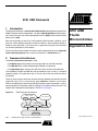
This document describes a device-side USB framework developed for Atmel® AT91
ARM® Thumb® based microcontrollers. It enables rapid development of USB-compliant class drivers such as the Mass Storage Device class (MSD) or the Communication
Device Class (CDC).
Most microcontrollers of the AT91 family embed a USB controller. However, since
there are several different controllers used in the devices, the framework provides a
hardware layer abstraction. This means that an application relying on this framework
can be easily ported to any AT91 device.
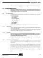
AT91 ARM
Thumb
Microcontrollers
Application Note
Finally, the presented framework has been carefully designed to be easily integrable
into an Operating System (OS), as well as to operate in a stand-alone way.
2. Framework Architecture
The following three-tiered structure is used:
• A hardware layer which performs low-level operations on the USB controller
• The USB API offers hardware-independent methods and structures
• The application layer, made up of a USB class driver and the user application
The framework includes the USB API and the hardware layer as well as a standard
requests handler. The application layer is built on top of that to provide the device
functionality.
To do so, there must be some form of communication between the USB API and the
application layer. This is carried out by using callbacks. Callbacks are functions
which are automatically called by the USB API to perform specific operations, such as
putting the device in low-power mode or handling class requests sent by the host. The
callback API is defined more thoroughly in Section 3.4 on page 8.
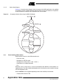
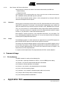
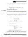
Figure 2-1.
USB Framework Architecture
USB class driver
User application
Standard
Specific
USB API
Methods
Events
Callbacks
Hardware layer
UDP Controller
Note:
Components in gray are part of the framework.
6263A–ATARM–10-Oct-06
3. Framework Description
The framework is comprised of several components:
• Standard USB structures
• USB API
– Structures
– Methods
• Callback API
• Standard Request handler
3.1
Standard USB Structures
The following standard structures have been implemented in the USB framework:
• Setup request data: S_usb_request
• Device descriptor: S_usb_device_descriptor
• Configuration descriptor: S_usb_configuration_descriptor
• Interface descriptor: S_usb_interface_descriptor
• Endpoint descriptor: S_usb_endpoint_descriptor
• Device_Qualifier descriptor: S_usb_device_qualifier_descriptor
• String descriptor zero: S_usb_language_id
For more information about how these structures are defined and used, refer to Section 5.2.2 on
page 16 and to chapter 9 of the USB specification 2.0.
3.2
USB API Structures
Several specific structures are used by the USB API to perform various operations, such as
invoking callbacks or accessing the USB controller.
There are four main structures:
• S_usb
• S_usb_driver
• S_usb_endpoint
• S_usb_callbacks
Note that it is possible to save RAM by declaring some of these objects as constants. By doing
so, they will be stored along with the code (in Flash, most of the time). Refer to the description of
each structure for more information.
3.2.1
S_usb
This is the main structure of the USB API. It contains the following elements:
• Pointer to the USB controller driver to use (S_usb_driver, see Section 3.2.2)
• List of endpoints used by the device (S_usb_endpoint, see Section 3.2.3)
• Number of endpoints used by the device
• List of callback functions (S_usb_callbacks, see Section 3.2.4)
• Pointer to the last setup packet received (S_usb_request, see Section 3.1)
2
Application Note
6263A–ATARM–10-Oct-06
Application Note
A pointer to an S_usb instance is needed to use all of the USB API methods. This pointer is
passed as an argument to callbacks so they do not require direct access to it.
The information stored in an S_usb object can be accessed using the following macros:
• USB_GetEndpoint: returns a pointer to the specified endpoint
• USB_GetSetup: returns a pointer to the last setup request received
• USB_GetDriverInterface, USB_GetDriverID, USB_GetDriverPMC: see Section 3.2.2.
This structure should be a constant to save RAM.
3.2.2
S_usb_driver
The S_usb_driver structure defines several parameters which are USB controller-dependent.
This includes:
• Address of the USB controller peripheral on the chip
• Peripheral ID
• ID to activate the 48 MHz clock in the Power Management Controller (PMC)
• Pointer to the driver-dependent methods
A default driver is provided for a chip if it has only one USB controller. Simply point to the sDefaultDriver variable when declaring your S_usb instance.
There are three methods to access the driver attributes:
• USB_GetDriverInterface: returns the address of USB controller peripheral
• USB_GetDriverID: returns the peripheral ID of the controller
• USB_GetDriverPMC: returns the PMC ID of the driver
Note that these functions take an S_usb (not a S_usb_driver) pointer as an argument. This is to
avoid having to extract the driver pointer from the S_usb object every time a driver attribute must
be accessed.
This structure should be a constant to save RAM.
3.2.3
S_usb_endpoint
Each USB endpoint used by the application must have a corresponding S_usb_endpoint
instance associated with it. The endpoint list is then stored in the S_usb structure (see Section
3.2.1).
Several attributes of an endpoint are stored in this structure, but only the number of FIFO banks
to use can be specified by the user. Other attributes include the endpoint current state, the current transfer descriptor, etc.
Two macros, USB_ENDPOINT_SINGLEBANK and USB_ENDPOINT_DUALBANK, are provided to easily declare endpoints. Please refer to the documentation of the corresponding USB
controller for information about the number of available FIFO banks for each endpoint.
3.2.4
S_usb_callbacks
This structure holds pointers to the various user-defined callbacks (see Section 3.4 on page 8
for a description of the callback API). The USB API uses those pointers to invoke the callbacks
when needed.
They are stored in the following order:
• Init
3
6263A–ATARM–10-Oct-06
• Reset
• Suspend
• Resume
• NewRequest
• StartOfFrame
Be sure to use the same order when declaring the S_usb_callbacks structure in your code.
Since most callbacks have the same arguments, not every compiler will give an error message if
two callbacks are inverted.
This structure should be a constant to save RAM.
3.3
USB API methods
The USB API provides several methods to perform the following operations:
• Changing the device state
• Handling events coming from the USB controller
• Modifying the behavior of an endpoint
• Transferring data
• Special functions
3.3.1
3.3.1.1
Controlling the Device State
Chapter 9 of the USB specification 2.0 describes the various states a device can be in. Most of
the methods of this API are used to change between those states.
USB_Init
This is the first method to call in a user application. Technically, it must occur just before entering
the Attached state. It performs the following actions:
• Endpoint state initialization
• D+ pull-up configuration and disabling
• Init callback invocation
A USB device uses a pull-up on the D+ line to signal its connection to the host. Depending on
the USB controller present on the chip, either an internal or external pull-up is used. In both
cases, its configuration is performed directly by this method. Please refer to the documentation
of a particular controller for more information about the D+ pull-up.
The Init callback has to perform several mandatory operations at this point. Section 3.4.2 on
page 9 gives more details on this step.
3.3.1.2
USB_Attach
Whenever a device gets attached to the host, it receives a +5V signal on the VBus line for powering. Conversely, when the cable is disconnected or the host is shut down, this signal
disappears.
This function monitors the VBus status to attach or detach the device from the bus, i.e., switch
between the Attached and Powered state of the USB state machine. Whenever the device gets
powered, the USB controller is enabled to start receiving commands from the host. When the
power goes down, USB_Attach disables the peripheral.
4
Application Note
6263A–ATARM–10-Oct-06
Application Note
This function triggers the Resume and the Suspend callbacks upon attachment/detachment.
Those callbacks are used to put the device into low-power mode if needed. More information is
given in Section 3.4.4 and Section 3.4.5 on page 10.
Note that if the device is bus-powered, i.e., its only power source is VBus, then this function
should be called once to power up the peripheral. Otherwise, it should be tied to a VBus monitoring routine. Most of the time, there will be a pin connected to VBus; a PIO interrupt can be used
to signal a state change and call the USB_Attach method.
3.3.1.3
USB_Connect, USB_Disconnect
These two methods control the state of the D+ pull-up. This makes it possible to connect or disconnect the device by software when needed. USB_Connect changes the device state from
Powered to Default, while USB_Disconnect changes from either Default, Address or Configured
to Powered.
Strictly speaking, the USB_Attach method should be called first to go from Attached to Powered,
then the software can call USB_Connect to enter the Default state. This makes no difference in
practice.
3.3.1.4
USB_SetAddress
USB_SetAddress extracts the information from the last received SETUP packet to either change
the device state from Default to Address or from Address to Default. The difference is made
depending on the value of the wValue field of the request.
This method must only be called right after the SET_ADDRESS request is received.
3.3.1.5
USB_SetConfiguration
This function operates in a way similar to USB_SetAddress. When the SETUP packet containing
a SET_CONFIGURATION request is received, USB_SetConfiguration should be called to
extract the new configuration value to adopt. If the wValue field of the request is non-zero, then
the device must adopt the new configuration and enter the Configuration state; otherwise, it
returns (or stays) in the Address state.
3.3.1.6
USB_GetState
As its name implies, this method simply returns the current state of the USB driver. The first six
bits of the returned value each indicate if a particular state is active:
• USB_STATE_ATTACHED (bit 0): Always set, since physical attachment or detachment from
the bus cannot be detected.
• USB_STATE_POWERED (bit 1): Set when VBus is present. Cleared when VBus is
disconnected.
• USB_STATE_DEFAULT (bit 2): Set when an End of bus reset operation completes. Cleared
when USB_Disconnect is called.
• USB_STATE_ADDRESS (bit 3): Set when a SET_ADDRESS request with a non-null
wValue field is received. Cleared when a SET_ADDRESS request with a null wValue field is
received.
• USB_STATE_CONFIGURED (bit 4): Set when a SET_CONFIGURATION request with a
non-null wValue field is received. Cleared when a SET_CONFIGURATION request with a null
wValue field is received.
• USB_STATE_SUSPENDED (bit 5): Set when the bus is idle. Cleared when the bus becomes
active again. The other bits indicate the state the device was in before being suspended.
5
6263A–ATARM–10-Oct-06
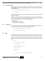
3.3.1.7
Device State Diagram
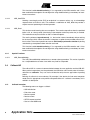
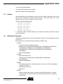
Figure 3-1 is the device state diagram (refer to chapter 9 of the USB specification 2.0), modified
to include the various methods described above. Note that since no method can suspend or
resume the device by software, the Suspended states are not shown.
Figure 3-1.
Changing the Device State using the USB API Methods
USB_Init
Attached
USB_Attach
USB_Attach
Powered
USB_Connect
USB_Disconnect
Default
USB_SetAddress
USB_SetAddress
Address
USB_SetConfiguration
USB_SetConfiguration
Configured
3.3.2
Event Handling (USB_Handler)
Several events can occur at the USB controller level:
• End of bus reset
• Reception of a SETUP packet
• Change of bus activity (active -> idle -> active ..)
• Completion of an endpoint operation
• Etc.
Whenever such an event occurs, it must be forwarded to the USB API to be handled in an
appropriate way. The USB_Handler method performs this functionality, so the controller interrupt
must be configured to call it.
Several callbacks can be triggered depending on the event notified by the controller:
• Suspend, when the bus is idle
6
Application Note
6263A–ATARM–10-Oct-06
Application Note
• Resume, when the bus becomes active again
• Reset, when an end-of-bus reset is detected
• NewRequest, when a setup packet is received on a control endpoint
• StartOfFrame, every 1 ms (for full-speed controllers) or 125 µs (for high-speed controllers)
More information about these callbacks and their expected behavior can be found in Section 3.4
on page 8.
3.3.3
Endpoint Behavior Modification
The USB API offers three functions to control how an endpoint operates.
The first one is used to actually configure the endpoint, and must thus be called prior to using
any other endpoint-related function. The other two provide ways to modify how an endpoint
acknowledges incoming packets.
3.3.3.1
USB_ConfigureEndpoint
This function is used to configure an endpoint at the USB controller level. An appropriate endpoint descriptor must be provided to do that. The descriptor is used to configure the endpoint
type (either Control, Bulk, Interrupt or Isochronous), direction (IN or OUT) and address.
Control endpoint 0 is automatically configured by the USB API when the End of bus reset event
is signalled by the USB controller. Therefore, there is no need to do it manually.
3.3.3.2
USB_Stall
The USB_Stall method causes an endpoint to acknowledge its next received packet with a
STALL handshake. Further packets are then handled normally.
Most of the time, this method should be used with endpoint 0 to signal the host that the device
cannot process a command.
3.3.3.3
USB_Halt
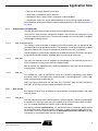
This method sets, clears or gets the Halt status of an endpoint (depending on the request
parameter). When in Halt mode, every received packet is acknowledged with a STALL handshake instead of being handled normally.
USB_Halt can be called either with the USB_SET_FEATURE, USB_CLEAR_FEATURE or
USB_GET_STATUS parameter to modify the endpoint Halt state.
3.3.4
Data Transfer
Data transfer (IN or OUT) on an endpoint can be performed by calling two methods, USB_Write
and USB_Read.
3.3.4.1
USB_Write
The USB_Write function sends a data payload on a specific endpoint. If the data payload equals
or exceeds the maximum packet size of the endpoint, then several IN transactions are necessary. This method should only be called on an IN or Control endpoint.
The write is performed asynchronously, i.e., the function returns immediately without waiting
for the transfer to finish. When the transfer is complete, an optional user-provided callback function is called. This makes it possible to create an OS-friendly synchronous function by locking
and unlocking a semaphore before and after each write.
7
6263A–ATARM–10-Oct-06
This function handles double-buffering, if it is supported by the USB controller and if it has
been enabled for the endpoint. Do not forget that using double-buffering is mandatory for isochronous transactions.
3.3.4.2
USB_SendZLP0
Sending a zero-length packet (ZLP) on endpoint 0 is a common action, e.g., to acknowledge
requests when no IN data is sent. This method is a redefinition of USB_Write that provides a
simpler means of performing this kind of operation.
3.3.4.3
USB_Read
This function reads incoming data on an endpoint. The transfer stops either when the provided
buffer is full, or a short packet (size inferior to the endpoint maximum packet size) is received.
This method must only be called on an OUT or Control endpoint.
The read is performed asynchronously, i.e., the function returns immediately without waiting
for the transfer to finish. When the transfer is complete, an optional user-provided callback function is called. This makes it possible to create an OS-friendly synchronous function by locking
and unlocking a semaphore before and after each read.
This function handles double-buffering, if it is supported by the USB controller and if it has
been enabled for the endpoint. Do not forget that using double-buffering is mandatory for isochronous transactions.
3.3.5
3.3.5.1
3.4
Special Functions
USB_RemoteWakeUp
The USB_RemoteWakeUp method starts a remote wakeup procedure. This makes it possible
for a suspended device to wake a host which may itself be suspended.
Callback API
The callback API is a means of communication between the user application and the USB API.
When particular operations must be performed, the USB driver calls several external functions,
referred to as callbacks. They can also be invoked to notify the user application of pending
events.
Defining all callbacks is not mandatory. For example, if the device shall not enter low-power
mode, then it is appropriate not to provide a Suspend callback. If a callback is mandatory, this is
notified in its description.
3.4.1
Callback Invocation
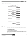
The following events can trigger a callback:
• USB initialization
• End of bus reset
• Device suspend
• Device resume
• SETUP request received
• Start of a new USB frame
8
Application Note
6263A–ATARM–10-Oct-06
Application Note
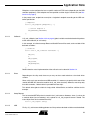
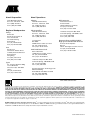
Figure 3-2.
Callback Invocation Flowchart
USB controller
USB API
Application
USB_Init
Initialization
Callback: Init
End of bus reset
USB_Handler
SETUP received
Callback: Reset
USB_Handler
Bus idle
Callback: NewRequest
USB_Handler
Bus activity
Callback: Suspend
USB_Handler
Start of USB frame
Callback: Resume
USB_Handler
Callback: StartOfFrame
Cable disconnected
Interrupt handler
USB_Attach
Callback: Suspend
Cable connected
Interrupt handler
USB_Attach
Callback: Resume
3.4.2
Init
The Init callback is invoked when the USB_Init method is called. It has to perform several mandatory steps to make it possible to use the API:
• If an OS is used, perform any specific operation to install the driver
• Configure USB controller interrupt
• Configure Vbus monitoring PIO and interrupt
The USB controller interrupt must be configured to call the USB_Handler API function when
triggered. This is necessary to have events happening at the USB controller level handled
appropriately by the API.
9
6263A–ATARM–10-Oct-06
If a PIO pin is connected to VBus, it is possible to monitor it by configuring the pin as an input
and enabling the PIO interrupt. The interrupt service routine should simply call the USB_Attach
function, which checks the Vbus line and either attaches or detaches the device accordingly.
Finally, if an OS is being used, then the driver should probably be installed prior to use. Interrupt
configuration may also be done differently. Please refer to the documentation of the OS for more
information.
This callback is mandatory.
3.4.3
Reset
When an End of bus reset has been detected, the Reset callback is triggered. The callback
should perform initialization or re-initialization of the user-level application. For example, a
class driver like MSD should re-initialize its internal state when a USB reset is performed.
3.4.4
Suspend
When the USB device enters the Suspended state, the USB API notifies this state change by
invoking the Suspend callback. This can happen either when the bus is idle or when the device
is disconnected from the USB.
If the device should enter low-power mode when suspended, then this callback must perform the
required operations to do so, e.g., switching to a slow clock, disabling PLLs, etc.
Note:
3.4.5
The electrical specification of the USB 2.0 defines a maximum current consumption of 500 µA for
suspended devices. This includes the current passing through pull-ups and pull-downs.
Resume
The Resume callback is invoked when the USB device leaves the Suspended state and returns
to its previous state (either Powered, Default, Address or Configured). This may happen when
activity is detected on the USB, or when the device gets connected.
If the device was in low-power mode because of the Suspend callback, then this callback must
perform the necessary operations to return the device into a normal operating mode, e.g.,
switching to a fast clock.
3.4.6
NewRequest
When a SETUP request is received on a control endpoint, the USB API layer triggers the
NewRequest callback to notify the user application. The received request can then be accessed
through the corresponding S_usb structure (see Section 3.2.1 on page 2).
SETUP packets are used for class-specific requests (e.g. GetMaxLUN in MSD) as well as standard USB requests (e.g. SetConfiguration). The former are described in USB Device Class
Documents, such as the Mass Storage Bulk Only 1.0; the latter are defined in the USB Specification 2.0.
Note that SETUP requests which are not understood by the device should be acknowledged
with a STALL handshake. This notifies the host that the device cannot process the command.
This callback is mandatory.
3.4.7
StartOfFrame
Every 1 ms (for a full-speed device) or 125 µs (for a high-speed device) a new USB frame starts.
A callback can be invoked whenever this occurs.
10
Application Note
6263A–ATARM–10-Oct-06
Application Note
Because the start-of-frame interrupt puts some stress on the processor (since it is called a lot), it
is only activated if the corresponding callback is defined.
3.5
Standard Request Handling
Chapter 9 of the USB specification 2.0 defines a set of standard requests which have to be
implemented by all devices. Since most class drivers treat those requests in the standard way,
the USB framework provides a way to easily do that.
3.5.1
STD_RequestHandler
This method identifies standard requests and handles them in an appropriate way. It can answer
the following commands:
• GET_DESCRIPTOR
• SET_ADDRESS
• SET_CONFIGURATION
• GET_CONFIGURATION
• CLEAR_FEATURE
• SET_FEATURE
• GET_STATUS
Simply using this standard request handler enables a device to be enumerated correctly.
3.5.1.1
Get Descriptor
The GET_DESCRIPTOR request is used by the host to retrieve information about the device by
means of several descriptors.
The standard request handler simply sends the corresponding descriptor to the host. How these
descriptors are provided to the function is discussed in Section 3.5.2.
3.5.1.2
Set Address
Whenever the host wants to change the device state from Default to Address, or vice-versa, it
sends a SET_ADDRESS request. The wValue field contains the new address of the device; if it
is null, then the device returns to the Default state.
The USB_SetAddress function is called to perform this operation. Note that a zero-length packet
must be sent prior to doing that, to acknowledge the SETUP transfer.
3.5.1.3
Set Configuration & Get Configuration
The SET_CONFIGURATION request makes it possible for the host to select between one or
more configurations for the device. GET_CONFIGURATION is used to retrieve the currently
selected one.
Those two requests are handled in a very basic way by STD_RequestHandler: it assumes that
the device has only one configuration. Therefore, the SET_CONFIGURATION request is simply
acknowledged with a zero-length packet, and GET_CONFIGURATION is answered with either 0
or 1. If the user application needs more than one configuration, it will be the duty of the class
driver handler to service those requests.
In addition, when the SET_CONFIGURATION request causes the device to enter the Configured state, the standard request handler calls the USB_ConfigureEndpoint method for each
endpoint used by the device;
11
6263A–ATARM–10-Oct-06
3.5.1.4
Clear Feature, Set Feature & Get Status
Several features of a device can either be activated or deactivated by the USB host:
• Remote wakeup
• Endpoint Halt state
Three requests can be used to either set, clear or get the status of these two features:
SET_FEATURE, CLEAR_FEATURE and GET_STATUS.
The STD_RequestHandler method answers a Halt state operation by calling the USB_Halt
method on the endpoint with the request.
3.5.2
Structures
Several pieces of information must be known to the STD_RequestHandler to be able to process
some SETUP commands. For example, all the descriptors (configuration, etc.) used by the
device are needed since they must be sent to the host when a GET_DESCRIPTOR is received.
The S_std_class structure is a “standard USB class driver” object used to hold the required information. It must be passed as an argument to the STD_RequestHandler method. Another
structure, S_std_descriptors, is used to store the descriptors list.
When defining a custom class driver, its first component should be S_std_class object. This
way, it will be possible to cast the custom driver as a S_std_class instance, which will be directly
usable by the STD_RequestHandler method.
3.5.3
Usage
The NewRequest callback is used to notify the user application that a new SETUP request has
been received. SETUP request can either be class-specific or standard.
The correct way to handle incoming requests is to first process class-specific requests using a
class handler. For example, a Mass Storage implementation will define the NewRequest callback to call MSD_RequestHandler. This function will handle the necessary requests, and
forward the rest to STD_RequestHandler.
If a request cannot be processed, STD_RequestHandler will STALL control endpoint 0.
4. Framework Usage
4.1
File Architecture
The USB framework is made up of the following files:
core_at91stdio.c: input/output methods for <stdio.h>, to use the DBGU port for debug
core_board.c, core_board.h: board-related definitions and methods
core_common.h: common definitions and methods
core_device.c, core_device.h: chip-related definitions and methods
core_main.c: basic enumeration program
core_standard.c, core_standard.h: standard request handler and structures
core_startup.s: device startup code in assembly language
core_trace.h: debug methods and definitions
12
Application Note
6263A–ATARM–10-Oct-06
Application Note
core_usb.h: USB API definitions
core_udp.c: UDP controller driver methods
Makefile: makefile used to build the project
4.2
Headers
When programming your own application, most if not all the headers described in the file architecture of the framework must be included. However, since each header has its own
dependencies, they must be included in a particular order.
Here is the standard inclusion order:
#include "core_common.h"
#include "core_device.h"
#include "core_board.h"
#include "core_trace.h"
#include "core_usb.h"
#include "core_standard.h"
If a custom class driver has been added, then its header must probably be linked last, after the
core_standard.h file.
4.3
Building the Framework
A Makefile is provided to make it easier to compile the framework. The nmake program is necessary to use it.
Several options are available to build the framework in different ways:
• TARGET
– Target chip for which to build the program.
– Possible values: AT91SAM7S32, AT91SAM7S321, AT91SAM764, AT91SAM7128,
AT91SAM7256, AT91SAM7512, AT91SAM7SE32, AT91SAM7SE256,
AT91SAM7SE512, AT91SAM7X128, AT91SAM7X256, AT91SAM7X512,
AT91SAM7A3.
– Default: AT91SAM7S64.
• BOARD
– Board used with the chip.
– Possible values: AT91SAM7SEK, AT91SAM7SEEK, AT91SAM7XEK,
AT91SAM7A3EK.
– Default: AT91SAM7SEK.
• DEBUG
– This option tells the linker to add debug symbols and create an .axf file for debugging
the project with AXD.
– Possible values: YES, NO.
– Default: NO.
• REMAP
– Optional, compiles the program so it copies itself in RAM and performs a memory
remap operation. This can be useful to save on power consumption or to speed up
the execution.
13
6263A–ATARM–10-Oct-06
– Possible values: YES, NO.
– Default: NO.
• LEDS
– Optional, enables the program to use the board LEDs to signal device activity.
– Possible values: YES, NO.
– Default: NO.
• TRACES
– Optional, enables the program to use the DBGU port to output debug traces.
– Possible values: YES, NO.
Here are some usage examples:
• Default compilation: builds the project for an AT91SAM7S64 on a AT91SAM7S-EK:
nmake
• Builds the framework for an AT91SAM7X256 on an AT91SAM7X-EK, in debug mode:
nmake TARGET=AT91SAM7X256 BOARD=AT91SAM7XEK DEBUG=YES
• Minimum power consumption: remap, no LED display and no debug traces:
nmake REMAP=YES LEDS=NO TRACES=NO
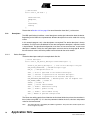
5. Example: USB Enumeration
This section is a step-by-step guide on how to use the USB framework to produce a simple program that performs USB enumeration. In this example, everything is put into a single file. You
can look at the core_main.c file provided with the framework to view the end result.
5.1
Including the Necessary Headers
Prior to using the framework, several header files have to be included. Please refer to Section
4.2 on page 13 for more information on that step.
5.2
Declaring Global Variables
Several object instances are necessary to use the various functions and methods of the USB
framework. They are detailed below.
5.2.1
USB Driver
The very first step is to declare the USB driver which is then used by the Class driver. The S_usb
structure is used as a container for several variables (see Section 3.2.1 on page 2), which must
therefore be created first.
5.2.1.1
Endpoints
Depending on the application, a particular number of endpoints have to be defined. For example, an MSD driver needs three endpoints whereas a CDC driver needs four. Refer to the
corresponding specification for more information about the required number of endpoints. Since
this example should only perform the USB enumeration, it will declare only one endpoint: Control endpoint 0.
14
Application Note
6263A–ATARM–10-Oct-06
Application Note
Endpoints can be configured to have a specific number of FIFO banks (depending on the USB
controller peripheral), each endpoint must be specified as either single- or dual-bank (see Section 3.2.3 on page 3).
In the present case, endpoint 0 can only be a single-bank endpoint according to the UDP controller specification:
// Endpoints
static S_usb_endpoint pEndpoints[] = {
// Control endpoint 0
USB_ENDPOINT_SINGLEBANK,
};
5.2.1.2
Callbacks
A S_usb_callbacks (see Section 3.2.4 on page 3) global variable must be declared with pointers
to the used callbacks (or null values).
In this example, all callbacks except Reset and StartOfFrame will be used, so the variable will be
declared as follows:
// Callbacks
static const S_usb_callbacks sCallbacks = {
CBK_Init,
0,
CBK_Suspend,
CBK_Resume,
CBK_NewRequest,
0
};
Details about the actual implementation of the callbacks can be found in Section 5.4.
5.2.1.3
Driver
Depending on the chip used, there may or may not be a need to declare a low-level driver
variable.
Since a chip may have more than one USB controller, it is necessary to specify which one will be
used by the USB API (hence the need for the S_usb_driver structure). However, most chips only
have one controller; a default driver is provided for those chips.
This default driver global variable is simply called sDefaultDriver, and will be sufficient for this
example.
5.2.1.4
Setup Request
The last received SETUP packet is stored in the S_usb instance. However, since S_usb can be
a constant object (to save memory), only a pointer to a S_usb_request instance is stored. The
actual object must thus be defined manually:
static S_usb_request sSetup;
5.2.1.5
USB
Finally, a S_usb instance holding pointers to all the previous declared variables must be defined:
15
6263A–ATARM–10-Oct-06
// USB instance
static const S_usb sUsb = {
&sDefaultDriver,
pEndpoints,
1,
&sCallbacks,
&sSetup
};
Please refer to Section 3.2.1 on page 2 for more information about the S_usb structure.
5.2.2
Descriptors
The USB specification 2.0 defines a set of descriptors used to give information about the device.
Depending on the USB class implemented, different descriptors have to be used with varying
values.
In this example program, only a few descriptors are required. The device descriptor is always
mandatory, so it will have to be defined. At least one configuration descriptor is required, so one
is implemented. The described configuration must have at least one interface, so one more
descriptor is needed. Finally, four string descriptors are used: one for the language ID, one for
the manufacturer name, one for the product name and one for the serial number.
5.2.2.1
Device Descriptor
The device descriptor used by this example looks like this:
// Device descriptor
static const S_usb_device_descriptor sDeviceDescriptor = {
sizeof(S_usb_device_descriptor), // Size of this descriptor in bytes
USB_DEVICE_DESCRIPTOR, // DEVICE Descriptor Type
USB_20, // USB Specification 2.0
0x00, // Class is specified in the interface descriptor.
0x00, // Subclass is specified in the interface descriptor.
0x00, // Protocol is specified in the interface descriptor.
USB_ENDPOINT0_MAXPACKETSIZE, // Maximum packet size for endpoint zero
USB_VENDOR_ATMEL, // Vendor ID
0x0000, // Product ID
0x0001, // Device release number
0x01, // Index 1: manufacturer string
0x02, // Index 2: product string
0x03, // Index 3: serial number string
0x01 // Number of possible configurations
};
The values are nothing special here. Note that the first three fields always have the same data in
them (unless using USB 1.1). It is also very common to define the class, subclass and protocol
values at the interface level.
Note:
16
The vendor ID value is provided by the USB-IF organization. The product ID is vendor-specific and
can be assigned any value.
Application Note
6263A–ATARM–10-Oct-06
Application Note
5.2.2.2
Configuration & Interface Descriptors
When the configuration descriptor is requested by the host, via the GET_DESCRIPTOR command, the device must not only transmit this descriptor but also all the necessary interface and
endpoint descriptors.
In order to do that easily, a structure must be defined for holding all the information. This way,
the data to send is contiguous, making the request much simpler to fulfill. In the current example,
the configuration descriptor must be followed by the first interface descriptor. The following
structure is declared for that:
// Device configuration structure
typedef struct {
S_usb_configuration_descriptor sConfiguration;
S_usb_interface_descriptor
sInterface;
} S_core_configuration_descriptor;
Now, the actual descriptors can be declared:
// Configuration & interface descriptors
static const S_core_configuration_descriptor sConfigurationDescriptor = {
// Configuration descriptor
{
sizeof(S_usb_configuration_descriptor), // Size of this descriptor
USB_CONFIGURATION_DESCRIPTOR, // CONFIGURATION descriptor
sizeof(S_core_configuration_descriptor), // Total length
0x01, // Number of interfaces
0x01, // Value to select this configuration
0x00, // Index for describing this configuration
USB_CONFIG_SELF_NOWAKEUP, // Device attributes
USB_POWER_MA(100) // Maximum power consumption
},
// Interface Descriptor
{
sizeof(S_usb_interface_descriptor), // Size of this descriptor
USB_INTERFACE_DESCRIPTOR, // INTERFACE Descriptor Type
0x00, // Number of this interface
0x00, // Value used to select this setting
0x00, // Number of endpoints used (excluding endpoint 0)
USB_CLASS_DEVICE, // Interface class
0x00, // Interface subclass
0x00, // Interface protocol
0x00 // Index of string descriptor
},
};
17
6263A–ATARM–10-Oct-06
Again, those are very generic values. For the interface descriptor, most of them are zeroed. This
is because this example does not implement any functionality other than doing the USB
enumeration.
5.2.2.3
String Descriptors
Only one structure is provided by the USB framework to declare string descriptors: for the language ID. This is because those descriptors have a variable size, and can most of the time be
declared as a character array.
Declaring the language ID is very straightforward:
// Language ID
static const S_usb_language_id sLanguageID = {
USB_STRING_DESCRIPTOR_SIZE(1),
USB_STRING_DESCRIPTOR,
USB_LANGUAGE_ENGLISH_US
};
The USB_STRING_DESCRIPTOR_SIZE macro is used to calculate the size of a string descriptor given its content. Since USB string descriptors must be in unicode format, each character
takes up two bytes; the macro takes the number of characters in the string as an argument, multiplies it by two and adds the size of the string descriptor header.
Other descriptors are simply defined like this:
// Manufacturer description
static const char pManufacturer[] = {
USB_STRING_DESCRIPTOR_SIZE(5),
USB_STRING_DESCRIPTOR,
USB_UNICODE('A'),
USB_UNICODE('T'),
USB_UNICODE('M'),
USB_UNICODE('E'),
USB_UNICODE('L')
};
The USB_UNICODE macro simply appends a zero (0) to the array in order to convert a standard
ACSCII character to a UNICODE one.
5.2.3
Class Driver
The demonstration program is going to use the standard request handler discussed in Section
3.5 on page 11 to perform the USB enumeration. To be able to do that, several structures must
be declared.
5.2.3.1
Descriptors List
The S_std_class object needs a pointer to a list of descriptors. This is necessary to be able to
answer the GET_DESCRIPTOR request. An S_std_descriptors instance can be used to do that.
Since it needs a list of string descriptors, this must be created first:
// List of string descriptors
static const char *pStringDescriptors[] = {
18
Application Note
6263A–ATARM–10-Oct-06
Application Note
(char *) &sLanguageID,
pManufacturer,
pProduct,
pSerial
};
The actual descriptors list can then be instantiated:
// List of descriptors used by the device
static S_std_descriptors sDescriptors = {
&sDeviceDescriptor,
(S_usb_configuration_descriptor *) &sConfigurationDescriptor,
pStringDescriptors,
0 // List of endpoint descriptors (excluding endpoint 0), not used
};
The core configuration descriptor, which is actually made up of the configuration descriptor and
the first interface descriptor (see Section 5.2.2 on page 16), has to be cast to the
S_usb_configuration_descriptor type.
5.2.3.2
Class Driver Instance
Finally, the class driver can be instancied:
// Basic class driver
static S_std_class sClass = {
&sUsb,
&sDescriptors,
};
While this example only contains a pointer to the USB driver and the list of descriptors, it is probably more complex in an actual USB class implementation.
5.3
5.3.1
Interrupt Service Routines
USB Controller Interrupt
The USB controller peripheral generates an interrupt when an event occurs. Since that event
must be forwarded to the USB_Handler method, an interrupt service routine must be installed to
do that.
A standard ISR should simply call the USB_Handler function:
void ISR_Driver()
{
USB_Handler(&sUsb);
}
5.3.2
VBus PIO Interrupt
The Vbus power line can be monitored (if a PIO pin is connected to it) by the user application to
enable or disable the USB controller peripheral when the device is connected/disconnected. To
19
6263A–ATARM–10-Oct-06
do that, an interrupt must be programmed when the status of VBus changes. The ISR should
call the USB_Attach function as follows:
void ISR_VBus()
{
USB_Attach(&sUsb);
// Acknowledge the interrupt by making a dummy write in ISR
AT91C_PIO_VBUS->PIO_ISR = 0;
}
How to register both ISRs is detailed in Section 5.4.
5.4
Callbacks
A typical application based on this USB framework needs to instantiate most of the callbacks
available. This section describes how to do that for a simple enumeration program.
5.4.1
Init
When an OS is not being used, the primary function that the Init callback must perform is interrupt handler installation. The two previously defined ISRs (see Section 5.3) are thus configured
and enabled here, along the configuration of the VBus pin:
static void CBK_Init(const S_usb *pUsb)
{
// Configure and enable the USB controller interrupt
AT91F_AIC_ConfigureIt(AT91C_BASE_AIC,
USB_GetDriverID(pUsb),
AT91C_AIC_PRIOR_LOWEST,
AT91C_AIC_SRCTYPE_INT_HIGH_LEVEL,
ISR_Driver);
AT91F_AIC_EnableIt(AT91C_BASE_AIC, USB_GetDriverID(pUsb));
// Configure VBus monitoring
BRD_ConfigureVBus(USB_GetDriverInterface(pUsb));
// Configure and enable the Vbus detection interrupt
AT91F_AIC_ConfigureIt(AT91C_BASE_AIC,
AT91C_ID_VBUS,
AT91C_AIC_PRIOR_LOWEST,
AT91C_AIC_SRCTYPE_INT_HIGH_LEVEL,
ISR_VBus);
AT91F_PIO_InterruptEnable(AT91C_PIO_VBUS, AT91C_VBUS);
AT91F_AIC_EnableIt(AT91C_BASE_AIC, AT91C_ID_VBUS);
}
If the target board uses the USB as its power supply, or no pin is connected to the VBus line,
then the Init callback should call the USB_Attach method instead of doing the second ISR
initialization.
20
Application Note
6263A–ATARM–10-Oct-06
Application Note
5.4.2
Suspend & Resume
The Suspend callback is used by the USB API to notify the device that it should enter low-power
mode if required. Since a method is provided to perform this operation in the core_device.c file,
it can be called here:
static void CBK_Suspend(const S_usb *pUsb)
{
DEV_Suspend();
}
The Resume callback has to perform the reverse operation, which can be done by calling the
DEV_Resume method.
Note that it is not necessary to disable the USB controller logic (transceiver, clocks, peripheral)
here. This is done directly by the USB_Handler function prior to triggering the callback. Typically,
the DEV_Suspend method must carry out the following operations:
• Disable the PLL
• Switch to the slow 32 kHz clock
• Turn off the clocks of used peripherals
5.4.3
NewRequest
Since this example software should only perform the USB enumeration, the NewRequest callback can simply forward the call to the standard request handler method:
static void CBK_NewRequest(const S_usb *pUsb) {
STD_RequestHandler(&sClass);
}
5.5
Main
The Main function of the program is used for driver initialization (Class and USB), software connection of the device (by using USB_Connect), and implementation of the product functionality.
In this case, the Main performs the first two steps. After that, since the enumeration is done
through the event handler and the device does not do anything, it can simply enter an infinite
loop:
int main()
{
// Initialize the USB driver
USB_Init(&sUsb);
// Try to connect the device
USB_Connect(&sUsb);
// Main loop
while (1) {
// Put USB class driver implementation here
}
}
21
6263A–ATARM–10-Oct-06
6. Revision History
Table 6-1.
Document Ref.
Comments
6263
First issue
22
Change Request
Ref.
Application Note
6263A–ATARM–10-Oct-06
Atmel Corporation
2325 Orchard Parkway
San Jose, CA 95131, USA
Tel: 1(408) 441-0311
Fax: 1(408) 487-2600
Regional Headquarters
Europe
Atmel Sarl
Route des Arsenaux 41
Case Postale 80
CH-1705 Fribourg
Switzerland
Tel: (41) 26-426-5555
Fax: (41) 26-426-5500
Asia
Room 1219
Chinachem Golden Plaza
77 Mody Road Tsimshatsui
East Kowloon
Hong Kong
Tel: (852) 2721-9778
Fax: (852) 2722-1369
Japan
9F, Tonetsu Shinkawa Bldg.
1-24-8 Shinkawa
Chuo-ku, Tokyo 104-0033
Japan
Tel: (81) 3-3523-3551
Fax: (81) 3-3523-7581
Atmel Operations
Memory
2325 Orchard Parkway
San Jose, CA 95131, USA
Tel: 1(408) 441-0311
Fax: 1(408) 436-4314
RF/Automotive
Theresienstrasse 2
Postfach 3535
74025 Heilbronn, Germany
Tel: (49) 71-31-67-0
Fax: (49) 71-31-67-2340
Microcontrollers
2325 Orchard Parkway
San Jose, CA 95131, USA
Tel: 1(408) 441-0311
Fax: 1(408) 436-4314
La Chantrerie
BP 70602
44306 Nantes Cedex 3, France
Tel: (33) 2-40-18-18-18
Fax: (33) 2-40-18-19-60
ASIC/ASSP/Smart Cards
1150 East Cheyenne Mtn. Blvd.
Colorado Springs, CO 80906, USA
Tel: 1(719) 576-3300
Fax: 1(719) 540-1759
Biometrics/Imaging/Hi-Rel MPU/
High-Speed Converters/RF Datacom
Avenue de Rochepleine
BP 123
38521 Saint-Egreve Cedex, France
Tel: (33) 4-76-58-30-00
Fax: (33) 4-76-58-34-80
Zone Industrielle
13106 Rousset Cedex, France
Tel: (33) 4-42-53-60-00
Fax: (33) 4-42-53-60-01
1150 East Cheyenne Mtn. Blvd.
Colorado Springs, CO 80906, USA
Tel: 1(719) 576-3300
Fax: 1(719) 540-1759
Scottish Enterprise Technology Park
Maxwell Building
East Kilbride G75 0QR, Scotland
Tel: (44) 1355-803-000
Fax: (44) 1355-242-743
Literature Requests
www.atmel.com/literature
Disclaimer: The information in this document is provided in connection with Atmel products. No license, express or implied, by estoppel or otherwise, to any
intellectual property right is granted by this document or in connection with the sale of Atmel products. EXCEPT AS SET FORTH IN ATMEL’S TERMS AND CONDITIONS OF SALE LOCATED ON ATMEL’S WEB SITE, ATMEL ASSUMES NO LIABILITY WHATSOEVER AND DISCLAIMS ANY EXPRESS, IMPLIED OR STATUTORY
WARRANTY RELATING TO ITS PRODUCTS INCLUDING, BUT NOT LIMITED TO, THE IMPLIED WARRANTY OF MERCHANTABILITY, FITNESS FOR A PARTICULAR
PURPOSE, OR NON-INFRINGEMENT. IN NO EVENT SHALL ATMEL BE LIABLE FOR ANY DIRECT, INDIRECT, CONSEQUENTIAL, PUNITIVE, SPECIAL OR INCIDENTAL DAMAGES (INCLUDING, WITHOUT LIMITATION, DAMAGES FOR LOSS OF PROFITS, BUSINESS INTERRUPTION, OR LOSS OF INFORMATION) ARISING OUT
OF THE USE OR INABILITY TO USE THIS DOCUMENT, EVEN IF ATMEL HAS BEEN ADVISED OF THE POSSIBILITY OF SUCH DAMAGES. Atmel makes no
representations or warranties with respect to the accuracy or completeness of the contents of this document and reserves the right to make changes to specifications
and product descriptions at any time without notice. Atmel does not make any commitment to update the information contained herein. Unless specifically provided
otherwise, Atmel products are not suitable for, and shall not be used in, automotive applications. Atmel’s products are not intended, authorized, or warranted for use
as components in applications intended to support or sustain life.
© 2006 Atmel Corporation. All rights reserved. Atmel®, logo and combinations thereof, Everywhere You Are ® and others are registered trademarks or trademarks of Atmel Corporation or its subsidiaries. ARM ®, the ARMPowered ® logo, Thumb ® and others are registered trademarks or
trademarks of ARM Ltd. Other terms and product names may be trademarks of others.
6263A–ATARM–10-Oct-06