1
SmartFusion2 SoC FPGA High Speed
DDR Interfaces
User’s Guide
SmartFusion2 SoC FPGA High Speed DDR Interfaces User’s Guide
Table of Contents
About This Guide 5
Purpose . . . . . . . . . . . . . . . . . . . . . . . . . . . . . . . . . . . . . . . . . . . . . . . . . . . . . . . . . . . . . . . . . . . . . . . . . . . . . . . . . .
Contents . . . . . . . . . . . . . . . . . . . . . . . . . . . . . . . . . . . . . . . . . . . . . . . . . . . . . . . . . . . . . . . . . . . . . . . . . . . . . . . . . .
Additional Documentation . . . . . . . . . . . . . . . . . . . . . . . . . . . . . . . . . . . . . . . . . . . . . . . . . . . . . . . . . . . . . . . . . . . .
Related Documents . . . . . . . . . . . . . . . . . . . . . . . . . . . . . . . . . . . . . . . . . . . . . . . . . . . . . . . . . . . . . . . . . . . . . . . . .
5
5
5
6
Tutorials . . . . . . . . . . . . . . . . . . . . . . . . . . . . . . . . . . . . . . . . . . . . . . . . . . . . . . . . . . . . . . . . . . . . . . . . . . . . . . . . . . . . . . . . . 6
1 MDDR Subsystem . . . . . . . . . . . . . . . . . . . . . . . . . . . . . . . . . . . . . . . . . . . . . . . . . . . . . . . . . . . . . . . . .-7
Introduction . . . . . . . . . . . . . . . . . . . . . . . . . . . . . . . . . . . . . . . . . . . . . . . . . . . . . . . . . . . . . . . . . . . . . . . . . . . . . . . 7
Features . . . . . . . . . . . . . . . . . . . . . . . . . . . . . . . . . . . . . . . . . . . . . . . . . . . . . . . . . . . . . . . . . . . . . . . . . . . . . . . . . . . . . . . . . 7
Memory Configurations . . . . . . . . . . . . . . . . . . . . . . . . . . . . . . . . . . . . . . . . . . . . . . . . . . . . . . . . . . . . . . . . . . . . . . . . . . . . . . 8
Performance . . . . . . . . . . . . . . . . . . . . . . . . . . . . . . . . . . . . . . . . . . . . . . . . . . . . . . . . . . . . . . . . . . . . . . . . . . . . . . . . . . . . . . 9
I/O Utilization . . . . . . . . . . . . . . . . . . . . . . . . . . . . . . . . . . . . . . . . . . . . . . . . . . . . . . . . . . . . . . . . . . . . . . . . . . . . . . . . . . . . . 10
Functional Description . . . . . . . . . . . . . . . . . . . . . . . . . . . . . . . . . . . . . . . . . . . . . . . . . . . . . . . . . . . . . . . . . . . . . . 10
Architecture Overview . . . . . . . . . . . . . . . . . . . . . . . . . . . . . . . . . . . . . . . . . . . . . . . . . . . . . . . . . . . . . . . . . . . . . . . . . . . . . .
Port List . . . . . . . . . . . . . . . . . . . . . . . . . . . . . . . . . . . . . . . . . . . . . . . . . . . . . . . . . . . . . . . . . . . . . . . . . . . . . . . . . . . . . . . . .
Initialization . . . . . . . . . . . . . . . . . . . . . . . . . . . . . . . . . . . . . . . . . . . . . . . . . . . . . . . . . . . . . . . . . . . . . . . . . . . . . . . . . . . . . .
Details of Operation . . . . . . . . . . . . . . . . . . . . . . . . . . . . . . . . . . . . . . . . . . . . . . . . . . . . . . . . . . . . . . . . . . . . . . . . . . . . . . .
10
11
19
21
How to Use the MDDR . . . . . . . . . . . . . . . . . . . . . . . . . . . . . . . . . . . . . . . . . . . . . . . . . . . . . . . . . . . . . . . . . . . . . . 28
Design Flow . . . . . . . . . . . . . . . . . . . . . . . . . . . . . . . . . . . . . . . . . . . . . . . . . . . . . . . . . . . . . . . . . . . . . . . . . . . . . . . . . . . . .
Use Model 1: Accessing MDDR from FPGA Fabric Through the AXI Interface . . . . . . . . . . . . . . . . . . . . . . . . . . . . . . . . . .
Use Model 2: Accessing MDDR from FPGA Fabric Through the AHB Interface . . . . . . . . . . . . . . . . . . . . . . . . . . . . . . . . .
Use Model 3: Accessing MDDR from Cortex-M3 Processor . . . . . . . . . . . . . . . . . . . . . . . . . . . . . . . . . . . . . . . . . . . . . . . . .
Use Model 4: Accessing MDDR from the HPDMA . . . . . . . . . . . . . . . . . . . . . . . . . . . . . . . . . . . . . . . . . . . . . . . . . . . . . . . .
DDR Memory Device Examples . . . . . . . . . . . . . . . . . . . . . . . . . . . . . . . . . . . . . . . . . . . . . . . . . . . . . . . . . . . . . . . . . . . . . .
28
42
46
48
50
50
MDDR Configuration Registers . . . . . . . . . . . . . . . . . . . . . . . . . . . . . . . . . . . . . . . . . . . . . . . . . . . . . . . . . . . . . . . 54
SYSREG Configuration Register Summary . . . . . . . . . . . . . . . . . . . . . . . . . . . . . . . . . . . . . . . . . . . . . . . . . . . . . . . . . . . . . 54
DDR Controller Configuration Register Summary . . . . . . . . . . . . . . . . . . . . . . . . . . . . . . . . . . . . . . . . . . . . . . . . . . . . . . . . . 55
DDR Controller Configuration Register Bit Definitions . . . . . . . . . . . . . . . . . . . . . . . . . . . . . . . . . . . . . . . . . . . . . . . . . . . . . 59
PHY Configuration Register Summary . . . . . . . . . . . . . . . . . . . . . . . . . . . . . . . . . . . . . . . . . . . . . . . . . . . . . . . . . . . . . . . . 104
PHY Configuration Register Bit Definitions . . . . . . . . . . . . . . . . . . . . . . . . . . . . . . . . . . . . . . . . . . . . . . . . . . . . . . . . . . . . . 108
DDR_FIC Configuration Registers Summary . . . . . . . . . . . . . . . . . . . . . . . . . . . . . . . . . . . . . . . . . . . . . . . . . . . . . . . . . . . 150
DDR_FIC Configuration Register Bit Definitions . . . . . . . . . . . . . . . . . . . . . . . . . . . . . . . . . . . . . . . . . . . . . . . . . . . . . . . . . 151
Glossary . . . . . . . . . . . . . . . . . . . . . . . . . . . . . . . . . . . . . . . . . . . . . . . . . . . . . . . . . . . . . . . . . . . . . . . . . . . . . . . . 160
Acronyms . . . . . . . . . . . . . . . . . . . . . . . . . . . . . . . . . . . . . . . . . . . . . . . . . . . . . . . . . . . . . . . . . . . . . . . . . . . . . . . . . . . . . . 160
List of Changes . . . . . . . . . . . . . . . . . . . . . . . . . . . . . . . . . . . . . . . . . . . . . . . . . . . . . . . . . . . . . . . . . . . . . . . . . . 160
2 Fabric DDR Subsystem . . . . . . . . . . . . . . . . . . . . . . . . . . . . . . . . . . . . . . . . . . . . . . . . . . . . . . . . . . .-161
Introduction . . . . . . . . . . . . . . . . . . . . . . . . . . . . . . . . . . . . . . . . . . . . . . . . . . . . . . . . . . . . . . . . . . . . . . . . . . . . . 161
Features . . . . . . . . . . . . . . . . . . . . . . . . . . . . . . . . . . . . . . . . . . . . . . . . . . . . . . . . . . . . . . . . . . . . . . . . . . . . . . . . . . . . . . .
Memory Configurations . . . . . . . . . . . . . . . . . . . . . . . . . . . . . . . . . . . . . . . . . . . . . . . . . . . . . . . . . . . . . . . . . . . . . . . . . . . .
Performance . . . . . . . . . . . . . . . . . . . . . . . . . . . . . . . . . . . . . . . . . . . . . . . . . . . . . . . . . . . . . . . . . . . . . . . . . . . . . . . . . . . .
I/O Utilization . . . . . . . . . . . . . . . . . . . . . . . . . . . . . . . . . . . . . . . . . . . . . . . . . . . . . . . . . . . . . . . . . . . . . . . . . . . . . . . . . . . .
161
162
163
164
Functional Description . . . . . . . . . . . . . . . . . . . . . . . . . . . . . . . . . . . . . . . . . . . . . . . . . . . . . . . . . . . . . . . . . . . . . 164
Architecture Overview . . . . . . . . . . . . . . . . . . . . . . . . . . . . . . . . . . . . . . . . . . . . . . . . . . . . . . . . . . . . . . . . . . . . . . . . . . . . .
Port List . . . . . . . . . . . . . . . . . . . . . . . . . . . . . . . . . . . . . . . . . . . . . . . . . . . . . . . . . . . . . . . . . . . . . . . . . . . . . . . . . . . . . . . .
Initialization . . . . . . . . . . . . . . . . . . . . . . . . . . . . . . . . . . . . . . . . . . . . . . . . . . . . . . . . . . . . . . . . . . . . . . . . . . . . . . . . . . . . .
Details of Operation . . . . . . . . . . . . . . . . . . . . . . . . . . . . . . . . . . . . . . . . . . . . . . . . . . . . . . . . . . . . . . . . . . . . . . . . . . . . . .
164
165
172
175
How to Use the FDDR . . . . . . . . . . . . . . . . . . . . . . . . . . . . . . . . . . . . . . . . . . . . . . . . . . . . . . . . . . . . . . . . . . . . . 182
Design Flow . . . . . . . . . . . . . . . . . . . . . . . . . . . . . . . . . . . . . . . . . . . . . . . . . . . . . . . . . . . . . . . . . . . . . . . . . . . . . . . . . . . . 182
Use Model 1: Accessing FDDR from FPGA Fabric Through AXI Interface . . . . . . . . . . . . . . . . . . . . . . . . . . . . . . . . . . . . 193
Use Model 2: Accessing FDDR from FPGA Fabric Through AHB Interface . . . . . . . . . . . . . . . . . . . . . . . . . . . . . . . . . . . . 196
Revision 2
2
Table of Contents
DDR Memory Device Examples . . . . . . . . . . . . . . . . . . . . . . . . . . . . . . . . . . . . . . . . . . . . . . . . . . . . . . . . . . . . . . . . . . . . . 201
FDDR Configuration Registers . . . . . . . . . . . . . . . . . . . . . . . . . . . . . . . . . . . . . . . . . . . . . . . . . . . . . . . . . . . . . . 203
FDDR SYSREG Configuration Register Summary . . . . . . . . . . . . . . . . . . . . . . . . . . . . . . . . . . . . . . . . . . . . . . . . . . . . . . . 204
FDDR SYSREG Configuration Register Bit Definitions . . . . . . . . . . . . . . . . . . . . . . . . . . . . . . . . . . . . . . . . . . . . . . . . . . . 205
Glossary . . . . . . . . . . . . . . . . . . . . . . . . . . . . . . . . . . . . . . . . . . . . . . . . . . . . . . . . . . . . . . . . . . . . . . . . . . . . . . . . 214
Acronyms . . . . . . . . . . . . . . . . . . . . . . . . . . . . . . . . . . . . . . . . . . . . . . . . . . . . . . . . . . . . . . . . . . . . . . . . . . . . . . . . . . . . . . 214
List of Changes . . . . . . . . . . . . . . . . . . . . . . . . . . . . . . . . . . . . . . . . . . . . . . . . . . . . . . . . . . . . . . . . . . . . . . . . . . 214
3 DDR Bridge . . . . . . . . . . . . . . . . . . . . . . . . . . . . . . . . . . . . . . . . . . . . . . . . . . . . . . . . . . . . . . . . . . . .-215
Introduction . . . . . . . . . . . . . . . . . . . . . . . . . . . . . . . . . . . . . . . . . . . . . . . . . . . . . . . . . . . . . . . . . . . . . . . . . . . . . 215
Functional Description . . . . . . . . . . . . . . . . . . . . . . . . . . . . . . . . . . . . . . . . . . . . . . . . . . . . . . . . . . . . . . . . . . . . . 216
Architecture Overview . . . . . . . . . . . . . . . . . . . . . . . . . . . . . . . . . . . . . . . . . . . . . . . . . . . . . . . . . . . . . . . . . . . . . . . . . . . . . 216
Details of Operation . . . . . . . . . . . . . . . . . . . . . . . . . . . . . . . . . . . . . . . . . . . . . . . . . . . . . . . . . . . . . . . . . . . . . . . . . . . . . . 217
How to Use DDR Bridge . . . . . . . . . . . . . . . . . . . . . . . . . . . . . . . . . . . . . . . . . . . . . . . . . . . . . . . . . . . . . . . . . . . 220
Design Flow . . . . . . . . . . . . . . . . . . . . . . . . . . . . . . . . . . . . . . . . . . . . . . . . . . . . . . . . . . . . . . . . . . . . . . . . . . . . . . . . . . . . 220
Use Model 1: High Speed Data Transactions from Cortex-M3 Processor . . . . . . . . . . . . . . . . . . . . . . . . . . . . . . . . . . . . . 222
Use Model 2: Selecting Non-Bufferable Region . . . . . . . . . . . . . . . . . . . . . . . . . . . . . . . . . . . . . . . . . . . . . . . . . . . . . . . . . 222
SYSREG Control Registers . . . . . . . . . . . . . . . . . . . . . . . . . . . . . . . . . . . . . . . . . . . . . . . . . . . . . . . . . . . . . . . . . 223
DDR Bridge Control Registers in MDDR and FDDR . . . . . . . . . . . . . . . . . . . . . . . . . . . . . . . . . . . . . . . . . . . . . . 224
Glossary . . . . . . . . . . . . . . . . . . . . . . . . . . . . . . . . . . . . . . . . . . . . . . . . . . . . . . . . . . . . . . . . . . . . . . . . . . . . . . . . 225
Acronyms . . . . . . . . . . . . . . . . . . . . . . . . . . . . . . . . . . . . . . . . . . . . . . . . . . . . . . . . . . . . . . . . . . . . . . . . . . . . . . . . . . . . . . 225
Terminology . . . . . . . . . . . . . . . . . . . . . . . . . . . . . . . . . . . . . . . . . . . . . . . . . . . . . . . . . . . . . . . . . . . . . . . . . . . . . . . . . . . . 225
4 Soft Memory Controller Fabric Interface Controller . . . . . . . . . . . . . . . . . . . . . . . . . . . . . . . . . . . . . .-227
Introduction . . . . . . . . . . . . . . . . . . . . . . . . . . . . . . . . . . . . . . . . . . . . . . . . . . . . . . . . . . . . . . . . . . . . . . . . . . . . . 227
Functional Description . . . . . . . . . . . . . . . . . . . . . . . . . . . . . . . . . . . . . . . . . . . . . . . . . . . . . . . . . . . . . . . . . . . . . 228
Port List . . . . . . . . . . . . . . . . . . . . . . . . . . . . . . . . . . . . . . . . . . . . . . . . . . . . . . . . . . . . . . . . . . . . . . . . . . . . . . . . . . . . . . . . 228
How to Use SMC_FIC . . . . . . . . . . . . . . . . . . . . . . . . . . . . . . . . . . . . . . . . . . . . . . . . . . . . . . . . . . . . . . . . . . . . . 233
Design Flow . . . . . . . . . . . . . . . . . . . . . . . . . . . . . . . . . . . . . . . . . . . . . . . . . . . . . . . . . . . . . . . . . . . . . . . . . . . . . . . . . . . . 233
Use Model 1: Accessing SDRAM from MSS Through CoreSDR_AXI . . . . . . . . . . . . . . . . . . . . . . . . . . . . . . . . . . . . . . . . 234
SYSREG Control Register for SMC_FIC . . . . . . . . . . . . . . . . . . . . . . . . . . . . . . . . . . . . . . . . . . . . . . . . . . . . . . . 236
Glossary . . . . . . . . . . . . . . . . . . . . . . . . . . . . . . . . . . . . . . . . . . . . . . . . . . . . . . . . . . . . . . . . . . . . . . . . . . . . . . . . 237
Acronyms . . . . . . . . . . . . . . . . . . . . . . . . . . . . . . . . . . . . . . . . . . . . . . . . . . . . . . . . . . . . . . . . . . . . . . . . . . . . . . . . . . . . . . 237
A List of Changes . . . . . . . . . . . . . . . . . . . . . . . . . . . . . . . . . . . . . . . . . . . . . . . . . . . . . . . . . . . . . . . . .-239
B Product Support . . . . . . . . . . . . . . . . . . . . . . . . . . . . . . . . . . . . . . . . . . . . . . . . . . . . . . . . . . . . . . . . .-241
Customer Service . . . . . . . . . . . . . . . . . . . . . . . . . . . . . . . . . . . . . . . . . . . . . . . . . . . . . . . . . . . . . . . . . . . . . . . .
Customer Technical Support Center . . . . . . . . . . . . . . . . . . . . . . . . . . . . . . . . . . . . . . . . . . . . . . . . . . . . . . . . . .
Technical Support . . . . . . . . . . . . . . . . . . . . . . . . . . . . . . . . . . . . . . . . . . . . . . . . . . . . . . . . . . . . . . . . . . . . . . . .
Website . . . . . . . . . . . . . . . . . . . . . . . . . . . . . . . . . . . . . . . . . . . . . . . . . . . . . . . . . . . . . . . . . . . . . . . . . . . . . . . .
Contacting the Customer Technical Support Center . . . . . . . . . . . . . . . . . . . . . . . . . . . . . . . . . . . . . . . . . . . . . .
241
241
241
241
241
Email . . . . . . . . . . . . . . . . . . . . . . . . . . . . . . . . . . . . . . . . . . . . . . . . . . . . . . . . . . . . . . . . . . . . . . . . . . . . . . . . . . . . . . . . . . 241
My Cases . . . . . . . . . . . . . . . . . . . . . . . . . . . . . . . . . . . . . . . . . . . . . . . . . . . . . . . . . . . . . . . . . . . . . . . . . . . . . . . . . . . . . . 242
Outside the U.S. . . . . . . . . . . . . . . . . . . . . . . . . . . . . . . . . . . . . . . . . . . . . . . . . . . . . . . . . . . . . . . . . . . . . . . . . . . . . . . . . . 242
ITAR Technical Support . . . . . . . . . . . . . . . . . . . . . . . . . . . . . . . . . . . . . . . . . . . . . . . . . . . . . . . . . . . . . . . . . . . . 242
3
R e vi s i o n 2
About This Guide
Purpose
This user's guide describes the high speed memory interfaces in SmartFusion®2 system-on-chip (SoC)
field programmable gate array (FPGA) devices. The high speed memory interfaces (microcontroller
subsystem double data rate (MDDR) subsystem and fabric double data rate (FDDR) subsystem) provide
access to double data rate (DDR) memories for high-speed data transfers and code execution. The DDR
subsystems functionality, configurations, and their use models are discussed in this user's guide.
Contents
This user's guide contains the following chapters:
•
Chapter 1 - MDDR Subsystem
•
Chapter 2 - Fabric DDR Subsystem
•
Chapter 3 - DDR Bridge
•
Chapter 4 - Soft Memory Controller Fabric Interface Controller
Additional Documentation
Table 1 lists additional documentation available on SmartFusion2 SoC FPGAs. Refer to the web page for
a complete and up-to-date listing: www.microsemi.com/soc/products/smartfusion2/docs.aspx.
Table 1 • Additional Documents
Document
Description
SmartFusion2 SoC FPGA Product Brief
This product brief provides an overview of SmartFusion2
family, features, and development tools.
SmartFusion2 SoC FPGA Datasheet
This datasheet contains SmartFusion2 DC and switching
characteristics.
SmartFusion2 Pin Descriptions
This document contains SmartFusion2 pin descriptions,
package outline drawings, and links to pin tables in Excel
format.
SmartFusion2 FPGA Fabric Architecture User's Guide SmartFusion2 SoC FPGAs integrate fourth generation
flash-based FPGA fabric. The FPGA fabric composed of
4-input look-up table (LUT) logic elements, includes
embedded memories and Mathblocks for DSP processing
capabilities. This document describes the SmartFusion2
FPGA
fabric
architecture,
embedded
memories,
Mathblocks, fabric routing, and I/Os.
SmartFusion2 Microcontroller Subsystem User's
Guide
SmartFusion2 devices integrate a hard microcontroller
subsystem (MSS). The MSS consists of a ARM®
Cortex™-M3 processor with embedded trace macrocell
(ETM), instruction cache, embedded memories, DMA
engines, communication peripherals, timers, real-time
counter (RTC), general purpose I/Os, and FPGA fabric
interfaces. This document describes the SmartFusion2 MSS
and its internal peripherals.
Revision 2
5
About This Guide
Table 1 • Additional Documents (continued)
Document
Description
SmartFusion2 SoC FPGA High Speed Serial
Interfaces User's Guide
SmartFusion2 devices integrate hard high-speed serial
interfaces (PCIe, XAUI/XGXS, SERDES) for accessing
external bulk memories. This document describes the
SmartFusion2 high-speed serial interfaces.
SmartFusion2 Clocking Resources User’s Guide
SmartFusion2 clocking resources include oscillators, FPGA
fabric global network, and clock conditioning circuitry
(CCCs) with dedicated phase-locked loops (PLLs). These
clocking resources provide flexible clocking schemes to the
on-chip hard IP blocks—MSS, fabric DDR (FDDR)
subsystem, and high-speed serial interfaces (PCIe,
XAUI/XGXS, SERDES)—and logic implemented in the
FPGA fabric.
SmartFusion2 Low Power Design User's Guide
In addition to low static power consumption during normal
operation, SmartFusion2 devices support an ultra-low-power
Static mode (Flash*Freeze mode) with power consumption
less than 1 mW. Flash*Freeze mode retains all the SRAM
and register data which enables fast recovery to Active
mode. This document describes the SmartFusion2
Flash*Freeze mode entry and exit mechanisms.
SmartFusion2 System Controller User's Guide
The system controller manages programming of the
SmartFusion2 device and handles system service requests.
The subsystems, interfaces, and system services in the
system controller are discussed in this user's guide.
SmartFusion2 Security and Reliability User's Guide
The SmartFusion2 device family incorporates essentially all
the security features that made third generation Microsemi
SoC devices the gold standard for security in the PLD
industry. Also included are unique design and data security
features and use models new to the PLD industry.
SmartFusion2 flash-based FPGA fabric has zero FIT
configuration rate due to its single event upset (SEU)
immunity, which is critical in reliability applications. This
document describes the SmartFusion2 security features and
error detection and correction (EDAC) capabilities.
SmartFusion2 Programming User's Guide
Describes different programming modes supported in
SmartFusion2 devices. High level schematics of these
programming methods are also provided as a reference.
Important board-level considerations are discussed.
Related Documents
Tutorials
Interfacing SmartFusion2 SoC FPGA with DDR3 Memory through MDDR Controller Tutorial.
6
R e vi s i o n 2
1 – MDDR Subsystem
Introduction
The MDDR is a hardened ASIC block for interfacing the DDR2, DDR3, and LPDDR1 memories. The
MDDR subsystem is used to access DDR memories for high-speed data transfers and code execution.
The MDDR subsystem includes a DDR memory controller, DDR PHY, and arbitration logic to support
multiple masters. DDR memory connected to the MDDR subsystem can be accessed by the MSS
masters and master logic implemented in the FPGA fabric (FPGA fabric master).
The MSS masters communicate with the MDDR subsystem through an MSS DDR bridge that provides
an efficient access path. FPGA fabric masters communicate with the MDDR subsystem through AXI or
AHB interfaces.
Features
•
Integrated on-chip DDR memory controller and PHY
•
Configurable to support LPDDR1, DDR2, and DDR3 memory devices
•
Up to 667 Mbps (333.33 MHz DDR) performance
•
Supports memory densities up to 4 GB
•
Supports 8-/16-/32-bit DDR standard dynamic random access memory (SDRAM) data bus width
modes
•
Supports a maximum of 8 memory banks
•
Supports 1, 2, or 4 ranks of memory
•
Single error correction and double error detection (SECDED) enable/disable feature
•
Supports DRAM burst lengths of 4, 8, or 16, depending on configured bus-width mode and DDR
type
•
Support for sequential and interleaved burst ordering
•
Programs internal control for ZQ short calibration cycles for DDR3 configurations
•
Supports dynamic scheduling to optimize bandwidth and latency
•
Supports self refresh entry and exit on software command
•
Supports deep power-down entry and exit on software command
•
Flexible address mapper logic to allow application specific mapping of row, column, bank, and
rank bits
•
Configurable support for 1T or 2T timing on the DDR SDRAM control signals
•
Supports autonomous DRAM power-down entry and exit caused by lack of transaction arrival for
programmable time
•
Advanced power-saving design includes necessary toggling of command, address, and data pins
Revision 2
7
MDDR Subsystem
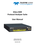
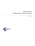
The system level block diagram of the MDDR subsystem is shown in Figure 1-1.
DDR IO
MSS
DDR
SDRAM
Cortex-M3 Processor
S
MDDR
D
I
64-Bit AXI
DDR PHY
DDR
Controller
AXI
Transaction
Controller
APB Config
Reg
IDC
MSS DDR
Bridge
Cache
Controller
S
D
IC
DDR_FIC
64-Bit AXI/Single
32-Bit AHBL/
Dual 32-Bit AHBL
16-Bit APB
DS
HPDMA
AHB Bus Matrix
FIC_2
FIC_0
FIC_1
USB
OTG
APB
Master
TSE
MAC
AXI/AHB
Master
FPGA FABRIC
SmartFusion2 SoC FPGA
Figure 1-1 • System Level MDDR Block Diagram
The MDDR subsystem accepts data transfer requests from AXI or AHB interfaces. Any read/write
transactions to the DDR memories can occur through the following four paths:
1. The Cortex-M3 processor can access DDR memories through the MSS DDR bridge for data and
code execution.
2. High performance DMA (HPDMA) controller can access DDR memories through the MSS DDR
bridge for high speed data transactions.
3. Other MSS masters (for example, FIC_0, FIC_1, and PDMA) can access DDR memories through
the MSS DDR bridge.
4. AXI or AHBL masters in the FPGA fabric can access DDR memories through DDR_FIC interface.
Memory Configurations
The SmartFusion2 SoC FPGA MDDR subsystem supports a wide range of common memory types,
configurations, and densities, as shown in Table 1-1 on page 9. If SECDED mode is enabled in the
MDDR controller, the external memory module must be connected to the following:
8
•
Data lines MDDR_DQ_ECC[3:0] when data width is x32
•
Data lines MDDR_DQ_ECC[1:0] when data width is x16
•
Data line MDDR_DQ_ECC[0] when data width is x8
R e vi s i o n 2
SmartFusion2 SoC FPGA High Speed DDR Interfaces User’s Guide
Table 1-1 • Supported Memory (DDR2, DDR3 and LPDDR1) Configurations
SmartFusion2 Devices
Memory
Density
128M
256M
512M
1G
2G
4G
Width
Width
(in SECDED
Mode)
M2S005/M2S0
10/M2S025
(VF400,
FG484)
M2S050
(VF400,
FG484)
M2S050
(FG896)
M2S075
(FG484)
M2S080/M2S
120 (FC1152)
×32
×36
–
–
✓
–
✓
×16
×18
✓
✓
✓
✓
✓
×8
×9
✓
–
–
–
✓
×32
×36
–
–
✓
–
✓
×16
×18
✓
✓
✓
✓
✓
×8
×9
✓
–
–
–
✓
×32
×36
–
–
✓
–
✓
×16
×18
✓
✓
✓
✓
✓
×8
×9
✓
–
–
–
✓
×32
×36
–
–
✓
–
✓
×16
×18
✓
✓
✓
✓
✓
x8
×9
✓
–
–
–
✓
×32
×36
–
–
✓
–
✓
×16
×18
✓
✓
✓
✓
✓
×8
×9
✓
–
–
–
✓
×32
×36
–
–
–
–
–
×16
×18
–
–
–
–
–
×8
×9
✓
–
–
–
✓
Performance
Table 1-2 shows the maximum and minimum data rates supported by MDDR subsystem for supported
memory types.
Table 1-2 • DDR Speeds
Memory Type
Maximum Data Rate (Mbps)
LPDDR1
400 Mbps (200 MHz)
DDR2
667 Mbps (333.33 MHz)
DDR3
667 Mbps (333.33 MHz)
Revision 2
9
MDDR Subsystem
I/O Utilization
Table 1-3 shows the I/O utilization for SmartFusion2 devices corresponding to supported bus widths. The
remaining I/Os in bank 0 can be used for general purposes.
Table 1-3 • I/O Utilization for SmartFusion2 Devices
M2S005/M2S010/
M2S025 (VF400,
FG484)
M2S050 (VF400,
FG484)
M2S050 (FG896)
M2S075 (FG484)
M2S080/M2S120
(FC1152)
36-bit
–
–
Bank0 (85 pins)
–
Bank2 (85 pins)
32-bit
–
–
Bank0 (76 pins)
–
Bank2 (76 pins)
18-bit
Bank0 (59 pins)
Bank0 (59 pins)
Bank0 (59 pins)
Bank0 (59 pins)
Bank2 (59 pins)
16-bit
Bank0 (52 pins)
Bank0 (52 pins)
Bank0 (52 pins)
Bank0 (52 pins)
Bank2 (52 pins)
9-bit
Bank0 (47 pins)
–
–
–
Bank2 (47 pins)
8-bit
Bank0 (41 pins)
–
–
–
Bank2 (41 pins)
MDDR Bus
Width
Functional Description
This section provides the detailed description of the MDDR subsystem which contains the following
sections:
•
Architecture Overview
•
Port List
•
Initialization
•
Details of Operation
Architecture Overview
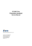
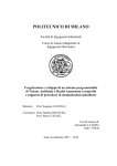
The functional block diagram of the MDDR subsystem is shown in Figure 1-2. The main components
include the DDR fabric interface controller (DDR_FIC), AXI transaction handler, DDR memory controller,
and DDR PHY. .
64-Bit AXI
Connected to MSS
DDR Bridge
64-Bit AXI /
Single 32-Bit
AHBL / Dual
32-Bit AHBL
Slave Interface
16-Bit APB
Configuration Bus
DDR_FIC
AXI
Transaction
Controller
DDR Controller
PHY
DDR
SDRAM
Configuration Registers
Figure 1-2 • MDDR Subsystem Functional Block Diagram
The DDR_FIC facilitates communication between the FPGA fabric masters and AXI transaction
controller. The DDR_FIC can be configured to provide either one 64-bit AXI slave interface or two
independent 32-bit AHB-Lite (AHBL) slave interfaces to the FPGA fabric masters.
The AXI transaction controller receives read and write requests from AXI masters (MSS DDR bridge and
DDR_FIC) and schedules for the DDR controller by translating them into DDR controller commands.
10
R e visio n 2
SmartFusion2 SoC FPGA High Speed DDR Interfaces User’s Guide
The DDR controller receives the commands from the AXI transaction controller. These commands are
queued internally and scheduled for access to the DDR SDRAM while satisfying DDR SDRAM
constraints, transaction priorities, and dependencies between the transactions. The DDR controller in
turn issues commands to the PHY module, which launches and captures data to and from the DDR
SDRAM.
The DDR PHY converts the DDR controller commands into the actual timing relationships and DDR
signaling necessary to communicate with the memory device.
The 16-bit APB configuration bus provides an interface to configure the MDDR subsystem registers.
Port List
Table 1-4 • MDDR Subsystem Interface Signals
Signal Name
Type
Polarity
Description
APB_S_PCLK
In
–
APB clock. This clock drives all the registers of the
APB interface.
APB_S_PRESET_N
In
Low
APB reset signal. This is an active low signal. This
drives the APB interface and is used to generate
the soft reset for the DDR controller as well.
MDDR_DDR_CORE_RESET_N
In
Low
Global reset. This resets the
DDR_FIC/DDRC/PHY/DDRAXI logic.
MDDR_DDR_AXI_S_RMW
In
High
AXI mode only Indicates whether all bytes of a
64-bit lane are valid for all beats of an AXI transfer.
0: Indicates that all bytes in all beats are valid in the
burst and the controller should default to write
commands.
1: Indicates that some bytes are invalid and the
controller should default to RMW commands. This
is classed as an AXI write address channel
sideband signal and is valid with the AWVALID
signal.
Bus Interfaces
AXI_SLAVE*
Bus
–
AXI slave interface 1.0 bus
AHB0_SLAVE*
Bus
–
AHB0 slave interface 3.0 bus
AHB1_SLAVE*
Bus
–
AHB1 slave interface 3.0 bus
APB_SLAVE
Bus
–
APB slave interface 3.0 bus
MDDR_CAS_N
Out
Low
DRAM CASN
MDDR_CKE
Out
High
DRAM CKE
MDDR_CLK
Out
–
DRAM single-ended clock – for differential pads
MDDR_CLK_N
Out
–
DRAM single-ended clock – for differential pads
MDDR_CS_N
Out
Low
DRAM CSN
MDDR_ODT
Out
High
DRAM ODT.
DRAM Interface
0: Termination Off
1: Termination On
MDDR_RAS_N
Out
Low
DRAM RASN
* AXI or AHB interface, depending on configuration.
Revision 2
11
MDDR Subsystem
Table 1-4 • MDDR Subsystem Interface Signals (continued)
Signal Name
Type
Polarity
MDDR_ RESET_N
Out
Low
DRAM reset for DDR3
MDDR_WE_N
Out
Low
DRAM WEN
MDDR_ADDR[15:0]
Out
–
Dram address bits
MDDR_BA[2:0]
Out
–
Dram bank address
MDDR_DM_RDQS[3:0]
In/out
–
DRAM data mask – from bidirectional pads
MDDR_DQS[3:0]
In/out
–
DRAM single-ended data strobe output – for
bidirectional pads
MDDR_DQS_N[3:0]
In/out
–
DRAM single-ended data strobe output – for
bidirectional pads
MDDR_DQ[31:0]
In/out
–
DRAM data input/output – for bidirectional pads
MDDR_DQ_ECC[3:0]
In/out
–
DRAM data input/output for SECDED
MDDR_DM_RDQS_ECC
In/out
High
DRAM single-ended data strobe output – for
bidirectional pads
MDDR_DQS_ECC
In/out
High
DRAM single-ended data strobe output – for
bidirectional pads
MDDR_DQS_ECC_N
In/out
Low
DRAM data input/output – for bidirectional pads
MDDR_DQS_TMATCH_0_IN
In
High
FIFO in signal. DQS enables input for timing match
between DQS and system clock. For simulations,
tie to MDDR_DQS_TMATCH_0_OUT.
MDDR_DQS_TMATCH_1_IN
In
High
FIFO in signal. DQS enables input for timing match
between DQS and system clock. For simulations,
tie to MDDR_DQS_TMATCH_1_OUT.
MDDR_DQS_TMATCH_0_OUT
Out
High
FIFO out signal. DQS enables output for timing
match between DQS and system clock. For
simulations, tie to MDDR_DQS_TMATCH_0_IN.
MDDR_DQS_TMATCH_1_OUT
Out
High
FIFO out signal. DQS enables output for timing
match between DQS and system clock. For
simulations, tie to MDDR_DQS_TMATCH_1_IN.
MDDR_DQS_TMATCH_ECC_IN
In
High
FIFO in signal. DQS enables input for timing match
between DQS and system clock. For simulations,
tie to MDDR_DQS_TMATCH_ECC_OUT.
Out
High
FIFO out signal. DQS enables output for timing
match between DQS and system clock. For
simulations,
tie
to
MDDR_DQS_TMATCH_ECC_IN.
MDDR_DQS_TMATCH_ECC_OUT
* AXI or AHB interface, depending on configuration.
12
R e visio n 2
Description
SmartFusion2 SoC FPGA High Speed DDR Interfaces User’s Guide
AXI Slave Interface
Table 1-5 shows the MDDR AXI slave interface signals with their descriptions. These signals will be
available only if MDDR interface is configured for AXI mode. For more details of AXI protocol refer to
AMBA AXI v1.0 protocol specification.
Table 1-5 • AXI Slave Interface Signals
Signal Name
MDDR_DDR_AXI_S_ARREADY
Direction
Polarity
Description
Output
High
Indicates whether or not the slave is
ready to accept an address and
associated control signals.
1: Slave ready
0: Slave not ready
MDDR_DDR_AXI_S_AWREADY
Output
High
Indicates that the slave is ready to
accept an address and associated
control signals.
1: Slave ready
0: Slave not ready
MDDR_DDR_AXI_S_BID[3:0]
Output
Indicates
response
ID.
The
identification tag of the write response.
MDDR_DDR_AXI_S_BRESP[1:0]
Output
Indicates write response. This signal
indicates the status of the write
transaction.
00: Normal access okay
01: Exclusive access okay
10: Slave error
11: Decode error
MDDR_DDR_AXI_S_BVALID
Output
High
Indicates whether a
response is available.
valid
write
1: Write response available
0: Write response not available.
MDDR_DDR_AXI_S_RDATA[63:0]
Output
Indicates read data.
MDDR_DDR_AXI_S_RID[3:0]
Output
Read ID tag. This signal is the ID tag of
the read data group of signals.
MDDR_DDR_AXI_S_RLAST
Output
MDDR_DDR_AXI_S_RRESP[1:0]
Output
High
Indicates the last transfer in a read
burst.
Indicates read response. This signal
indicates the status of the read transfer.
00: Normal access
01: Exclusive access
10: Slave error
11: Decode error
MDDR_DDR_AXI_S_RVALID
Output
Indicates whether the required read
data is available and the read transfer
can complete.
1: Read data available
0: Read data not available
Revision 2
13
MDDR Subsystem
Table 1-5 • AXI Slave Interface Signals (continued)
Signal Name
MDDR_DDR_AXI_S_WREADY
Direction
Polarity
Description
Output
High
Indicates whether the slave can accept
the write data.
1: Slave ready
0: Slave not ready
MDDR_DDR_MDDR_DDR_AXI_S_ARADDR[31:0]
Input
Indicates initial address of a read burst
transaction.
MDDR_DDR_AXI_S_ARBURST[1:0]
Input
Indicates burst type. The burst type,
coupled with the size information,
details how the address for each
transfer within the burst is calculated.
00: FIXED - Fixed-address burst FIFO
type
01: INCR - Incrementing-address burst
normal
sequential memory
10: WRAP - Incrementing-address
burst that wraps to a lower address at
the wrap boundary
11: Reserved
MDDR_DDR_AXI_S_ARID[3:0]
Input
Indicates identification tag for the read
address group of signals.
MDDR_DDR_AXI_S_ARLEN[3:0]
Input
Indicates burst length. The burst length
gives the exact number of transfers in a
burst.
0000: 1
0001: 2
0010: 3
0011: 4
0100: 5
0101: 6
0110: 7
0111: 8
1000: 9
1001: 10
1010: 11
1011: 12
1100: 13
1101: 14
1110: 15
1111: 16
14
R e visio n 2
SmartFusion2 SoC FPGA High Speed DDR Interfaces User’s Guide
Table 1-5 • AXI Slave Interface Signals (continued)
Signal Name
MDDR_DDR_AXI_S_ARLOCK[1:0]
Direction
Polarity
Input
Description
Indicates lock type. This signal
provides additional information about
the atomic characteristics of the read
transfer.
00: Normal access
01: Exclusive access
10: Locked access
11: Reserved
MDDR_DDR_AXI_S_ARSIZE[1:0]
Input
Indicates the maximum number of data
bytes to transfer in each data transfer,
within a burst.
00: 1
01: 2
10: 4
11: 8
MDDR_DDR_AXI_S_ARVALID
Input
High
Indicates the validity of read address
and control information.
1: Address and control information
valid
0: Address and control information not
valid
MDDR_DDR_AXI_S_AWADDR[31:0]
Input
Indicates write address. The write
address bus gives the address of the
first transfer in a write burst transaction.
MDDR_DDR_AXI_S_AWBURST[1:0]
Input
Indicates burst type. The burst type,
coupled with the size information,
details how the address for each
transfer within the burst is calculated.
00: FIXED - Fixed-address burst FIFOtype
01: INCR - Incrementing-address burst
normal
sequential memory
10: WRAP - Incrementing-address
burst that wraps to a lower address at
the wrap boundary
11: Reserved
MDDR_DDR_AXI_S_AWID[3:0]
Input
Revision 2
Indicates identification tag for the write
address group of signals.
15
MDDR Subsystem
Table 1-5 • AXI Slave Interface Signals (continued)
Signal Name
MDDR_DDR_AXI_S_AWLEN[3:0]
Direction
Polarity
Input
Description
Indicates burst length. The burst length
gives the exact number of transfers in a
burst. This information determines the
number of data transfers associated
with the address.
0000: 1
0001: 2
0010: 3
0011: 4
0100: 5
0101: 6
0110: 7
0111: 8
1000: 9
1001: 10
1010: 11
1011: 12
1100: 13
1101: 14
1110: 15
1111: 16
MDDR_DDR_AXI_S_AWLOCK[1:0]
Input
Indicates lock type. This signal
provides additional information about
the atomic characteristics of the write
transfer.
00: Normal access
01: Exclusive access
10: Locked access
11: Reserved
MDDR_DDR_AXI_S_AWSIZE[1:0]
Input
Indicates the maximum number of data
bytes to transfer in each data transfer,
within a burst.
00: 1
01: 2
10: 4
11: 8
MDDR_DDR_AXI_S_AWVALID
Input
High
Indicates whether or not valid write
address and control information are
available.
1: Address and control information
available
0: Address and control information not
available
16
R e visio n 2
SmartFusion2 SoC FPGA High Speed DDR Interfaces User’s Guide
Table 1-5 • AXI Slave Interface Signals (continued)
Signal Name
MDDR_DDR_AXI_S_BREADY
Direction
Polarity
Description
Input
High
Indicates whether or not the master
can accept the response information.
1: Master ready
0: Master not ready
MDDR_DDR_AXI_S_RREADY
Input
High
Indicates whether or not the master
can accept the read data and response
information.
1: Master ready
0: Master not ready
MDDR_DDR_AXI_S_WDATA[63:0]
Input
Indicates write data.
MDDR_DDR_AXI_S_WID[3:0]
Input
Indicates
response
ID.
The
identification tag of the write response.
MDDR_DDR_AXI_S_WLAST
Input
MDDR_DDR_AXI_S_WSTRB[7:0]
Input
MDDR_DDR_AXI_S_WVALID
Input
High
Indicates the last transfer in a write
burst.
Indicates which byte lanes to update in
memory.
High
Indicates whether or not valid write
data and strobes are available.
1: Write data and strobes available
0: Write data and strobes not available
MDDR_DQS_TMATCH_ECC_OUT
Out
High
FIFO out signal. DQS enables output
for timing match between DQS and
system clock. For simulations, tie to
MDDR_DQS_TMATCH_ECC_IN.
AHB Slave Interface
Table 1-6 shows the MDDR AHB slave interface signals with their descriptions. These signals will be
available only if MDDR interface is configured for single or dual AHB mode. For more details of AHB
protocol refer to AMBA AHB v3.0 protocol specification.
Table 1-6 • AHB Slave Interface Signals
Signal Name
Direction
Polarity
Description
MDDR_DDR_AHB0_S_HREADYOUT
Output
High
Indicates that a transfer has finished on the bus.
The signal is asserted Low to extend a transfer.
Input to Fabric master.
MDDR_DDR_AHB0_S_HRESP
Output
High
Indicates AHB transfer response to Fabric master.
MDDR_DDR_AHB0_S_HRDATA[31:0]
Output
Indicates AHB read data to Fabric master.
MDDR_DDR_AHB0_S_HSEL
Input
High
MDDR_DDR_AHB0_S_HADDR[31:0]
Input
Indicates AHB address initiated by Fabric master.
MDDR_DDR_AHB0_S_HBURST[2:0]
Input
Indicates AHB burst type from Fabric master.
MDDR_DDR_AHB0_S_HSIZE[1:0]
Input
Indicates AHB transfer size from Fabric master.
MDDR_DDR_AHB0_S_HTRANS[1:0]
Input
Indicates AHB transfer type from Fabric master.
Revision 2
Indicates AHB slave select signal from Fabric
master.
17
MDDR Subsystem
Table 1-6 • AHB Slave Interface Signals (continued)
Signal Name
Direction
Polarity
Description
MDDR_DDR_AHB0_S_HMASTLOCK
Input
High
Indicates AHB master lock signal from Fabric
master.
MDDR_DDR_AHB0_S_HWRITE
Input
High
Indicates AHB write control signal from Fabric
master.
MDDR_DDR_AHB0_S_HREADY
Input
High
Indicates that a transfer has finished on the bus.
Fabric master can drive this signal Low to extend a
transfer.
MDDR_DDR_AHB0_S_HWDATA[31:0]
Input
Indicates AHB write data from Fabric master.
Table 1-7 shows the MDDR AHB slave interface signals with their descriptions. These signals will be
available only if MDDR interface is configured for dual AHB mode.
Table 1-7 • MDDR AHB Slave Interface Signals
Signal Name
Direction
Polarity
Description
MDDR_DDR_AHB1_S_HREADYOUT
Output
High
Indicates that a transfer has finished on the bus.
The signal is asserted Low to extend a transfer.
Input to Fabric master.
MDDR_DDR_AHB1_S_HRESP
Output
High
Indicates AHB transfer response to Fabric master.
MDDR_DDR_AHB1_S_HRDATA[31:0]
Output
Indicates AHB read data to Fabric master.
MDDR_DDR_AHB1_S_HSEL
Input
High
Indicates AHB slave select signal from Fabric
master.
MDDR_DDR_AHB1_S_HADDR[31:0]
Input
Indicates AHB address initiated by Fabric master.
MDDR_DDR_AHB1_S_HBURST[2:0]
Input
Indicates AHB burst type from Fabric master.
MDDR_DDR_AHB1_S_HSIZE[1:0]
Input
Indicates AHB transfer size from Fabric master.
MDDR_DDR_AHB1_S_HTRANS[1:0]
Input
Indicates AHB transfer type from Fabric master.
MDDR_DDR_AHB1_S_HMASTLOCK
Input
High
Indicates AHB master lock signal from Fabric
master.
MDDR_DDR_AHB1_S_HWRITE
Input
High
Indicates AHB write control signal from Fabric
master.
MDDR_DDR_AHB1_S_HREADY
Input
High
Indicates that a transfer has finished on the bus.
Fabric master can drive this signal Low to extend a
transfer.
MDDR_DDR_AHB1_S_HWDATA[31:0]
Input
Indicates AHB write data from Fabric master.
APB Slave Interface
Table 1-8 shows the MDDR APB slave interface signals with their descriptions. For more details of APB
protocol refer to AMBA APB v3.0 protocol specification.
Table 1-8 • MDDR APB Slave Interface Signals
Signal Name
Direction
Polarity
MDDR_APB_S_PREADY
Output
High
Indicates APB Ready signal to Fabric master.
MDDR_APB_S_PSLVERR
Output
High
Indicates error condition on an APB transfer to
Fabric master.
MDDR_APB_S_PRDATA[15:0]
Output
18
Description
Indicates APB read data to Fabric master.
R e visio n 2
SmartFusion2 SoC FPGA High Speed DDR Interfaces User’s Guide
Table 1-8 • MDDR APB Slave Interface Signals (continued)
Signal Name
Direction
Polarity
Description
MDDR_APB_S_PENABLE
Input
High
Indicates APB enable from Fabric master. The
enable signal is used to indicate the second cycle
of an APB transfer.
MDDR_APB_S_PSEL
Input
High
Indicates APB slave select signal from Fabric
master
MDDR_APB_S_PWRITE
Input
High
Indicates APB write control signal form Fabric
master
MDDR_APB_S_PADDR[10:2]
Input
Indicates APB address initiated by Fabric master.
MDDR_APB_S_PWDATA[15:0]
Input
Indicates APB write data from Fabric master.
Initialization
Before the MDDR subsystem is active, it goes through an initialization phase and this process starts with
a reset sequence. For DDR3 memories, the initialization phase also includes ZQ calibration and DRAM
training.
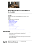
Reset Sequence
Figure 1-3 on page 20 shows the reset sequence for MDDR subsystem from power on reset stage. The
MDDR subsystem comes out of reset after MPLL Lock is asserted by the MSSS CCC. De-assertion of
MDDR_AXI_RESET_N signifies the end of the reset sequence. The MDDR reset can be generated by
asserting MDDR_CTLR_SOFTRESET bit in SOFT_RESET_CR to 1. The DDR controller performs
external DRAM memory reset and initialization as per the JEDEC specification, including reset, refresh,
and mode registers.
DDRIO Calibration
Each DDRIO has an ODT feature, which is calibrated depending on the DDR I/O standard. DDR I/O
calibration occurs after the DDR I/Os are enabled. If the impedance feature is enabled, impedance can
be programmed to the desired value in three ways:
•
Calibrate the ODT/driver impedance with a calibration block
•
Calibrate the ODT/driver impedance with fixed calibration codes
•
Configure the ODT/driver impedance to the desired value directly
The system register, MDDR_IO_CALIB_CR, can be configured for changing the ODT value to the
desired value. For more information on DDR I/O calibration, refer to the Configurable ODT and Driver
Impedance section of the "I/O's" chapter in the SmartFusion2 FPGA Fabric Architecture User's Guide.
Revision 2
19
MDDR Subsystem
PO_RESET_N
50 MHz Clock
Enable
Enable I/Os
DDRIO
Calibration
SC_MSS_RESET_N
MPLL Lock
MDDR_AXI_RESET_N
Figure 1-3 • Reset Sequence
ZQ Calibration
This is applicable for DDR3 only. The ZQ calibration command is used to calibrate DRAM output drivers
(RON) and on-die termination (ODT) values. The DDR3 SDRAM needs a longer time to calibrate RON
and ODT at initialization and a relatively smaller time to perform periodic calibrations.
The DDR controller performs ZQ calibration by issuing a ZQ calibration long (ZQCL) command and ZQ
calibration short (ZQCS) command.
ZQCL is used to perform initial calibration during the power-up initialization sequence. This command is
allowed for a period of tZQinit, as specified by memory vendor. The value of tZQinit can be configured
through register bits REG_DDRC_T_ZQ_LONG_NOP.
The ZQCS command is used to perform periodic calibration to account for voltage and temperature
variations. A shorter timing window is provided to perform calibration and transfer of values as defined by
timing parameter tZQCS. The tZQCS parameter can be configured through register bits
REG_DDRC_T_ZQ_SHORT_NOP.
Other activities are not performed by the controller for the duration of tZQinit and tZQCS. All DRAM
banks are precharged and tRP met before ZQCL or ZQCS commands are issued by the DDR controller.
DRAM Training
This is applicable for DDR3 only. If this option is enabled, the DDR controller performs PHY training after
reset. The order of training sequence is given below:
•
Write leveling
•
Read leveling
–
DQS gate training
–
Data eye training
Write Leveling
The write leveling process locates the delay at which the write DQS rising edge aligns with the rising
edge of the memory clock. By identifying this delay, the system can accurately align the write DQS within
the memory clock. The DDR controller drives subsequent write strobes for every write-to-write delay
specified by REG_DDRC_WRLVL_WW until the PHY drives the response signal High.
20
R e visio n 2
SmartFusion2 SoC FPGA High Speed DDR Interfaces User’s Guide
The DDR controller performs the following steps:
1. Sets up the DDR memory in Write leveling mode by sending the appropriate MR1 command.
2. Sets the write leveling enable bit for the PHY and sends out periodically timed write level strobes
to the PHY while sending out DEVSEL commands on the DDR memory command interface.
3. Once the PHY completes measurements, it sets the write level response bits, which then signal
the DDRC to stop the leveling process and lower the write leveling enable bit.
If the REG_DDRC_DFI_WR_LEVEL_EN bit is configured to 1, the write leveling enabled as part
of the initialization sequence.
Read Leveling
There are two read leveling modes:
1. DQS gate training
The purpose of gate training is to locate the optimum delay that can be applied to the DQS gate
such that it functions properly.
To enable the Read DQS gate training as part of the initialization sequence, set the
REG_DDRC_DFI_RD_DQS_GATE_LEVEL bit to 1.
2. Data eye training
The goal of data eye training is to identify the delay at which the read DQS rising edge aligns with
the beginning and end transitions of the associated DQ data eye.
To enable the Read data eye training as part of the initialization sequence, set the
REG_DDRC_DFI_RD_DATA_EYE_TRAIN bit to 1.
By identifying these delays, the system can calculate the midpoint between the delays and accurately
center the read DQS within the DQ data eye. The DDR controller drives subsequent read transactions for
every read-to-read delay specified by REG_DDRC_RDLVL_RR until the PHY drives the response signal
High.
The DDR controller performs the below steps:
1. Sets up the DDR memory for read leveling mode by sending the appropriate MR3 command,
which forces the DDR memory to respond to read commands with a 1-0-1-0-1 pattern.
2. Sets the relevant read leveling enable bit and sends out periodically timed read commands on the
DDR memory command interface.
3. Once the PHY completes its measurements, it sets the read level response bits, which then signal
the DDR controller to stop the leveling process and lower the read leveling enable bit.
Incremental Training
This is applicable for all DDR memories. The PHY supports incremental training where the data path
delays are incremented or decremented by 1 by the training logic. This mode can be enabled for
incremental read and write leveling by configuring the PHY_RD_WR_GATE_LVL_CR register. This
mode must be enabled only after initial training is completed. The PHY generates a flag bit when
incremental leveling fails, indicating that the interval was too large. The status of incremental training can
be read in the PHY_LEVELLING_FAILURE_SR register.
Details of Operation
This section provides a functional description of each block in the MDDR subsystem.
DDR_FIC
Figure 1-4 on page 22 shows the DDR_FIC block diagram.
Revision 2
21
MDDR Subsystem
AHB
64-Bit AXI / Single
32-Bit AHBL /
Dual 32-Bit AHBL
Slave Interface
AHB
MUX
AXI
MUX
AXI
16-Bit APB
Configuration Bus
DDR Bridge
AXI-AXI
Synchronous
Bridge
AXI Transaction
Controller
AXI
Configuration
Registers
Figure 1-4 • DDR_FIC Block Diagram
Fabric masters can access the MDDR subsystem in the following ways:
•
Single AXI-64 interface
•
Single AHB-32 interface
•
Dual AHB-32 bit interfaces
If the AXI-64 interface is selected, the DDR_FIC acts as an AXI to AXI synchronous bridge. In this mode,
DDR_FIC provides FPGA fabric masters to access the MDDR subsystem through locked transactions.
For this purpose, a user configurable 20-bit down counter keeps track of the duration of the locked
transfer. If the transfer is not completed before the down counter reaches zero, a single clock cycle pulse
interrupt is generated to the fabric interface.
If single or dual AHB-32 interfaces are selected, DDR_FIC converts the single/dual 32-bit AHBL master
transactions from the FPGA fabric to 64-bit AXI transactions. In this mode the DDR bridge, embedded as
part of the DDR_FIC, is enabled. The DDR bridge has an arbiter, which arbitrates read and write
requests from the two AHB masters on a round robin priority scheme. Refer to the "DDR Bridge" chapter
on page 215 for a detailed description.
The DDR_FIC input interface is clocked by the FPGA fabric clock and the MDDR is clocked by
MDDR_CLK from the MSS clock conditioning circuit (CCC). Clock ratios between MDDR_CLK and
DDR_FIC clock can vary. Supported ratios are shown in Table 1-10.
Clock ratios can be configured through Libero® System-on-Chip (SoC) software or through system
register MSSDDR_FACC1_CR. For more information, refer to the "MDDR Clock Configuration" section
on page 33.
Table 1-9 • MDDR_CLK to FPGA Fabric Clock Ratios
DIVISOR_A[1:0]
22
FIC64_DIVISOR[2:0]
MDDR_CLK: FPGA FABRIC Clock Ratio
00
000
1:1
00
001
2:1
00
010
4:1
00
100
8:1
00
101
16:1
01
000
2:1
01
001
4:1
01
010
8:1
01
100
16:1
11
000
3:1
R e visio n 2
SmartFusion2 SoC FPGA High Speed DDR Interfaces User’s Guide
Table 1-9 • MDDR_CLK to FPGA Fabric Clock Ratios (continued)
DIVISOR_A[1:0]
FIC64_DIVISOR[2:0]
MDDR_CLK: FPGA FABRIC Clock Ratio
11
001
6:1
11
010
12:1
AXI Transaction Controller
The AXI transaction controller receives 64-bit AXI transactions from various masters (MSS DDR bridge
and DDR_FIC) and translates them into DDR controller transactions. Figure 1-5 shows the block
diagram of the AXI transaction controller interfaced with the DDR controller.
The AXI transaction controller performs arbitration of the read/write requests initiated by AXI compliant
masters.
AXI Transaction Controller
Transaction
Handler
64-Bit AXI Bus
from DDR_FIC
AXI Slave
Interface
DDR
Controller
Priority Block
PHY
Re-Order Buffer
Figure 1-5 • AXI Transaction Controller Block Diagram
The AXI transaction controller comprises four major blocks:
1. AXI slave interface
2. Priority block
3. Transaction handler
4. Reorder buffer
AXI Slave Interfaces
The AXI transaction controller has two 64-bit AXI slave interfaces: one from the MSS DDR bridge and the
other from DDR_FIC. Each of the AXI slave ports is 64 bits wide and is in compliance with the standard
AXI protocol. Each transaction has an ID related to the master interface. Transactions with the same ID
are completed in order, while the transactions with different read IDs can be completed in any order,
depending on when the instruction is executed by the DDR controller. If a master requires ordering
between transactions, the same ID should be used.
The AXI slave interface has individual read and write ports. The read port queues read AXI transactions
and it can hold up to four read transactions. The write port handles only one write transaction at a time
and generates the handshaking signals on the AXI interface.
Revision 2
23
MDDR Subsystem
Priority Block
The priority block prioritizes AXI read/write transactions and provides control to the transaction handler.
AXI read transactions have higher priority. The default priority ordering is listed below:
1. Reads from the slave port of the MSS DDR bridge
2. Reads from the slave port of DDR_FIC
3. Writes from the slave port of the MSS DDR bridge
4. Writes from the slave port of DDR_FIC
The fabric master through DDR_FIC can be programmed to have a higher priority by configuring the
PRIORITY_ID and PRIORITY_ENABLE_BIT bit fields in the DDRC_AXI_FABRIC_PRI_ID_CR register.
Priority levels to other masters can be programmed as well, as shown in Table 1-10.
Table 1-10 • Priority Level Configuration
Priorities
Default
Priorities
PRIORITY_ENABLE_BIT=01
PRIORITY_ENABLE_BIT=10/11
Reads from I - Cache
1
1
2
Reads from DSG bus
2
2
3
Reads from HPDMA/AHB bus
3
4
4
Reads from Fabric master
having
the
ID
as
PRIORITY_ID
4
3
1
Writes from DSG bus
5
5
5
Writes from HPDMA/AHB bus
6
7
7
Writes from Fabric master
having
the
ID
as
PRIORITY_ID
7
6
6
Transactions
Transaction Handler
The transaction handler converts AXI transactions into DDR controller commands. The transaction
handler works on one transaction at a time from the read/write port queue that is selected by the priority
block.
The transaction handler has a write command controller and read command controller for write and read
transactions.
The write command controller fetches the command from the AXI slave write port and sends a pure write
instruction to the DDR controller. If SECDED is enabled, a read modified write (RMW) instruction is sent
to the DDR controller.
The read command controller generates read transactions to the DDR controller.
Reorder Buffer
The reorder buffer receives data from the DDR controller and orders the data as requested by the AXI
master when a single AXI transaction is split into multiple DDR controller transactions, depending on the
transfer size.
DDR Controller
The DDR controller receives requests from the AXI transaction controller, performs the address mapping
from system addresses to DRAM addresses (rank, bank, row, and column) and prioritizes requests to
minimize the latency of reads (especially high priority reads) and maximize page hits. It also ensures that
DRAM is properly initialized, all requests are made to DRAM legally (accounting for associated DRAM
constraints), refreshes are inserted as required, and the DRAM enters and exits various power-saving
modes appropriately. Figure 1-6 on page 25 shows the DDR controller connections in the MDDR
subsystem.
24
R e visio n 2
SmartFusion2 SoC FPGA High Speed DDR Interfaces User’s Guide
Data
Interface
AXI
Transaction
Controller
DDR Controller
Control
Interface
PHY
Training
Interface
16-Bit APB
Register Interface
Figure 1-6 • DDR Controller Block Diagram
The following sections describe key functions of the DDR controller.
Address Mapping
Read and write requests to the DDR controller requires a system address. The controller is responsible
for mapping this system address with rank, bank, row, and column address to DRAM.
The address mapper maps linear request addresses to DDR memory addresses by selecting the source
bit that maps to each and every applicable DDR memory address bit. The address map interface
registers can be configured to map source address bits to DRAM address (for more information, refer to
"Address Mapping" section on page 38 in Configuring the MDDR features).
Transaction Scheduling
The DDR controller schedules the read and write transactions to DDR memory. The DDR controller
classifies the transactions into three types, based on the commands from the AXI transaction controller:
•
Low priority reads (LPR)
•
High priority reads (HPR)
•
Writes (WR)
Each type of transaction has a queue and the queued transactions can be in normal state or in critical
state. The transactions in a queue moves from normal state to critical state when that transaction is not
serviced for a count of MAX_STARVE_X32 clocks. The MAX_STARVE_X32 values for each queue can
be configured using the DDR controller performance registers (refer "Performance" section on page 39).
The DDR controller completes the critical transactions with high priority.
Write Combine
The DDR controller combines multiple writes to the same address into a single write to DDR memory.
When a new write collides with the queued write, the DDR controller overwrites the data for the queued
write with that from the new write and only performs one write transaction. The write combine
functionality can be disabled by setting the register bit REG_DDRC_DIS_WC to 1.
SECDED
The DDR controller supports built-in SECDED capability for correcting single-bit errors and detecting
dual-bit errors. The SECDED feature can be enabled by setting REG_DDRC_MODE of
DDRC_MODE_CR to 101. When SECDED is enabled, the DDR controller adds 8 bits of SECDED data
to every 64 bits of data.
When SECDED is enabled, a write operation computes and stores a SECDED code along with the data,
and a read operation reads and checks the data against the stored SECDED code.
Revision 2
25
MDDR Subsystem
The SECDED bits are interlaced with the data bits as shown in Table 1-11.
Table 1-11 • SECDED DQ Lines at DDR
SECDED Data Pins
M2S005/M2S010/
M2S025 (VF400,
FG484)
Mode
M2S050 (VF400,
FG484)
Full bus width
mode
Half bus width MDDR_DQ_ECC
mode
[1:0]
MDDR_DQ_ECC
[1:0]
M2S050 (FG896)
M2S075 (FG484)
M2S080/M2S120
(FC1152)
MDDR_DQ_ECC
[3:0]
MDDR_DQ_ECC
[3:0]
MDDR_DQ_ECC MDDR_DQ_ECC
[1:0]
[1:0]
MDDR_DQ_ECC
[1:0]
Quarter bus MDDR_DQ_ECC
width mode
[0]
MDDR_DQ_ECC
[0]
When the controller detects a correctable SECDED error, it does the following:
•
Generates an interrupt signal which can be monitored by reading the interrupt status register,
DDRC_ECC_INT_SR. The ECCINT interrupt is mapped to the group0 interrupt signal
MSS_INT_M2F[12] of the fabric interface interrupt controller (FIIC).
•
Sends the corrected data to the read requested MSS/FPGA fabric master as part of the read
data.
•
Sends the SECDED error information to the DDRC_LCE_SYNDROME_1_SR register.
•
Performs a read-modify-write operation to correct the data present in the DRAM.
When the controller detects an uncorrectable error, it does the following:
•
Generates an interrupt signal which can be monitored by reading the interrupt status register,
DDRC_ECC_INT_SR. The ECCINT interrupt is mapped to the group0 interrupt signal
MSS_INT_M2F[12] of the FIIC.
•
Sends the data with error to the read requested MSS/FPGA fabric master as part of the read data.
•
Sends the SECDED error information to the DDRC_LUE_SYNDROME_1_SR register.
The following SECDED Registers can be monitored for identifying the exact location of an error in the
DDR SDRAM.
1. DDRC_LUE_ADDRESS_1_SR and DDRC_LUE_ADDRESS_2_SR give the row/bank/column
information of the SECDED unrecoverable error.
2. DDRC_LCE_ADDRESS_1_SR and DDRC_LCE_ADDRESS_2_SR give the row/bank/column
information of the SECDED error correction.
3. DDRC_LCB_NUMBER_SR indicates the location of the bit that caused the single-bit error in the
SECDED case (encoded value).
4. DDRC_ECC_INT_SR indicates whether the SECDED interrupt is because of a single-bit error or
double-bit error. The interrupt can be cleared by writing zeros to DDRC_ECC_INT_CLR_REG.
Power Saving Modes
The DDR controller can operate DDR memories in three power saving modes:
1. Precharge power-down
2. Self refresh
3. Deep power-down
Precharge Power-Down
If REG_DDRC_POWERDOWN_EN = 1, the DDR controller automatically keeps DDR memory in
precharge power-down mode when the period specified by REG_DDRC_POWERDOWN_TO_X32
register has passed, while the controller is idle (except for issuing refreshes). The controller automatically
performs the precharge power-down exit on any of the following conditions:
26
•
A refresh cycle is required to any rank in the system.
•
The controller receives a new request from the core logic.
•
REG_DDRC_POWERDOWN_EN is set to 0.
R e visio n 2
SmartFusion2 SoC FPGA High Speed DDR Interfaces User’s Guide
Self Refresh
The DDR controller keeps the DDR memory devices in Self-refresh mode whenever the
REG_DDRC_SELFREF_EN register bit is set and no reads or writes are pending in the controller.
The DDR controller can be programmed to issue single refreshes at a time
(REG_DDRC_REFRESH_BURST = 0) to minimize the worst-case impact of a forced refresh cycle. It
can be programmed to burst the maximum number of refreshes allowed for DDR (REFRESH_BURST=7,
for performing 8 refreshes at a time) to minimize the bandwidth lost when refreshing the pages.
The controller takes the DDR memory out of Self-refresh mode whenever the
REG_DDRC_SELFREF_EN input is deasserted or new commands are received by the controller.
Deep Power-Down
This is supported only for LPDDR1. The DDR controller puts the DDR SDRAM devices in Deep
Power-down mode whenever the REG_DDRC_DEEPPOWERDOWN_EN bit is set and no reads or
writes are pending in the DDR controller.
The DDR controller automatically exits Deep power-down mode and reruns the initialization sequence
when the REG_DDRC_DEEPPOWERDOWN_EN bit is reset to 0. The contents of DDR memory may
lost upon entry into deep Power-down mode.
DRAM Initialization
After Reset, the DDR controller initializes DDR memories through an initialization sequence, depending
on the type of DDR memory used. For more information on the initialization process, refer to the JEDEC
specification.
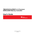
DDR PHY
SmartFusion2 devices have a built-in hardened DDR PHY block for interfacing with external DDR
memories. The DDR PHY processes read and write requests from the DDR controller and translate them
into specific signals within the timing constraints of the target DDR memory. The DDR PHY is composed
of functional units, including control slice, master DLL, ratio logic, and rank tracker, as shown in
Figure 1-7.
PHY
DQ[7:0]/DQS
Data Slice 0
Write Data Interface
MDLL
DQ[15:8]/DQS
Data Slice 1
Read Data Interface
DQ[23:16]/DQS
Data Slice 2
Training Interface
MDLL
DQ[31:24]/DQS
Data Slice 3
Rank
Tracker
DQ_ECC[3:0]/DQS_ECC
Data Slice 4
MDLL
Control Interface
FIFO
MDLL
Ratio
Logic
Memory Controls
Control Slice
Figure 1-7 • DDR PHY Block Diagram
Revision 2
27
MDDR Subsystem
The DDR PHY consists of five byte-wide data slices and one control slice. The data slice-4 is reserved
for SECDED and other data slices for the actual data transfer. The data slices 2 and 3 are not present in
the SmartFusion2 M2S005, M2S010, M2S025, and M2S075 devices. The unused data slices can be
disabled to save power by configuring the PHY_DATA_SLICE_IN_USE_CR register.
The byte-wide data slices contain the slave DLLs for write data, write DQS, and read DQS. The registers
can be configured to set the slave DLL ratio values, which are required when training is disabled. These
ratio values determine the delays to write data, write DQS, and read DQS. The PHY has a FIFO for
reading the data from all the slices in the same clock cycle.
The primary function of the PHY control slice is to control the timing of the generation of all the DDR
memory address and control signals. Ratio logic functions are used to adjust the signal timing for each
signal edge and these are controlled by the master DLL.
There are two kinds of DLLs: the master DLL and the slave DLL. The DLLs are responsible for creating
the precise timing windows required by the DDR memories to read and write data. The master DLL
measures the cycle period in terms of a number of taps and passes this number through the ratio logic to
the slave DLLs.
The Rank Tracker returns the rank number when the PHY gets a read/write request at the read/write
interface.
The training logic in the PHY determines the correct delay programming for the read data DQS and write
DQS signals. The training logic adjusts the delays and evaluates the results to locate the appropriate
edges. The DDR controller assists by enabling and disabling the leveling logic in the DDR memories and
the PHY by generating the necessary read commands or write strobes. The PHY informs the DDR
controller when it has completed training, which triggers the DDRC to stop generating commands and to
return to normal operation.
How to Use the MDDR
This section describes how to use the MDDR subsystem in the design. It contains the following sections:
•
Design Flow
•
Use Model 1: Accessing MDDR from FPGA Fabric Through the AXI Interface
•
Use Model 2: Accessing MDDR from FPGA Fabric Through the AHB Interface
•
Use Model 3: Accessing MDDR from Cortex-M3 Processor
•
Use Model 4: Accessing MDDR from the HPDMA
•
DDR Memory Device Examples
Design Flow
The flow chart (Figure 1-8 on page 29) illustrates the design flow for using the MDDR subsystem to
access external DDR memory.
The design flow consists of two parts:
1. Libero SoC flow – This includes configuring the type of DDR memory, choosing fabric master
interface type, clocking, and DDR I/O settings.
2. MDDR register initialization – The MDDR subsystem registers can be initialized using the
Cortex-M3 processor or FPGA fabric master. After MSS resets, the MDDR registers must be
configured according to application and DDR memory specification. The "MDDR Subsystem
Features Configuration" section on page 36 provides the details of required register configuration
for MDDR features. While configuring the registers, the soft reset to the DDR controller must be
asserted.
After releasing the soft reset, the DDR controller performs DDR memory initialization and sets the
status bits in DDRC_SR.
28
R e visio n 2
SmartFusion2 SoC FPGA High Speed DDR Interfaces User’s Guide
MSS external memory
configuration
MDDR clock
configuration
Libero design flow
FIC_2 configuration
Configure DDR I/O
settings in I/O Editor
(for example: ODT,
drive strength)
After MSS reset
Set the soft reset bit to 0
Configure the MDDR
register
Required steps for
MDDR initialization
Set the soft reset bit to 1
DDRC_SR = 0
YES
Start read/write to
DDR memory
Figure 1-8 • Design Flow
The configuration steps in the flow chart are explained below.
Revision 2
29
MDDR Subsystem
MSS External Memory Configuration
The MDDR subsystem is configured through the MSS external memory configurator, which is part of the
MSS configurator in the Libero SoC design software. Figure 1-9 shows the MSS External Memory
Configurator, which give the following choices for the external memory interface type:
1. Application accesses DDR
2. Application accesses SDRM through MSS memory access. (This option must be selected to
enable SMC_FIC. For more information on using SMC_FIC mode, refer to the "Soft Memory
Controller Fabric Interface Controller" chapter on page 227.)
Figure 1-9 • MSS External Memory Configuration
Application Accesses DDR
This option must be selected for accessing the external DDR memory through the MDDR subsystem.
Selecting this enables the configurator to configure the DDR memory type and fabric master interface
type.
Depending on the application requirement, select the memory type as DDR2, DDR3, or LPDDR. The
width of the memory can be selected as 32-bit, 16-bit, or 8-bit and the SECDED (ECC) can be enabled or
disabled.
To access the MDDR from the FPGA fabric, select From FPGA Fabric and the type of interface as AXI,
single AHBLite, or two AHB Interfaces. On completion of the configuration, the selected interface is
exposed in SmartDesign. The user logic in the FPGA fabric can access the DDR memory through MDDR
using these interfaces.
30
R e visio n 2
SmartFusion2 SoC FPGA High Speed DDR Interfaces User’s Guide
Edit Registers
The configurator also has an option Edit Registers for configuring the MDDR subsystem registers to
access external DDR memory. The register values must be calculated according to the application
requirements and DDR memory specifications. Refer to the "MDDR Subsystem Features Configuration"
section on page 36 for more information on the register configurations for using MDDR subsystem
features.
The firmware generated by Libero SoC stores these configurations and the MDDR subsystem registers
are initialized by the Cortex-M3 processor during the system_init phase of the firmware projects
(SoftConsole/IAR/Keil projects generated by Libero SoC).
Figure 1-10 shows the Registers Configuration window, which enables configuration of the MDDR
subsystem registers. The register/bit description is displayed at the bottom of the configurator on
selection of the register bits. The actual value field must be modified as per the application requirement.
The configurator also provides the option to import and export the register configurations.
Figure 1-10 • Edit Registers
Configuration files for accessing DDR3 memory on SmartFusion2 Development kit can be downloaded
from www.microsemi.com/soc/documents/MDDR3_16Bit_SB.zip.
Configuration files for accessing LPDDR memory on SmartFusion2 Starter kit can be downloaded from
www.microsemi.com/soc/documents/LPDDR_Emcraft_Config.zip.
Revision 2
31
MDDR Subsystem
An example of MDDR register configurations for operating the DDR3 memory (MT41J512M8RA) with
clock 333 MHz is shown in Table 1-12.
Table 1-12 • MDDR Configurations for Accessing DDR3 Memories at 333 MHz
Register Name and Configured Value
DDRC_DYN_REFRESH_1_CR
Field
Value to be Loaded
Desired Value
for
MT41J512M8RA
0x27 de
tRFC(min)
0×4F
237 ns
Speculative refresh
0×1E
90 ns
DDRC_DYN_REFRESH_2_CR
0×30 f
tRFEI
DDRC_INIT_MR_CR
0×61
0×61(97)×32 clks
= 9.3 us
0×520
Write recovery
3
DLL reset
Yes
CAS latency
6
Burst type
Sequential
Burst length
DDRC_INIT_EMR_CR
8
0×44
Additive latency (AL)
CL-1
Write levelization
Enable
DDRC_DRAM_BANK_TIMING_PARAM_CR
tRC
0×33
153 ns
tFAW
0×20
96 ns
DDRC_DRAM_RD_WR_LATENCY_CR
0×86
WL
4
RL
6
DDRC_DRAM_RD_WR_PRE_CR
0×1E5
Rd2pre
Wr2pre
DDRC_DRAM_MR_TIMING_PARAM_CR
63 ns
0×11
51 ns
0×58
tMOD
DDRC_DRAM_RAS_TIMING_CR
0×B
11 clks
0×10F
tRAS(max)
0×F
15×1024 = 46 us
tRAS(min)
0×8
24 ns
DDRC_DRAM_RD_WR_TRNARND_TIME_CR
0×178
Rd2wr
Wr2rd
DDRC_DRAM_T_PD_CR
32
0×15
0×B
11 clks
0×18
24 clks
0×33
tXP
3
3 clks
tCKE
3
3 clks
R e visio n 2
SmartFusion2 SoC FPGA High Speed DDR Interfaces User’s Guide
Table 1-12 • MDDR Configurations for Accessing DDR3 Memories at 333 MHz (continued)
Register Name and Configured Value
Field
DDRC_DRAM_BANK_ACT_TIMING_CR
Value to be Loaded
Desired Value
for
MT41J512M8RA
0×1947
tRP
7
21 ns
tRRD
4
12 ns
tCCD
2
2 clks
tRCD
6
18 ns
DDRC_PWR_SAVE_1_CR
0×506
Clks to power down
Self refresh gap
3
0×14(20)
3×32=96clks
20×32=640clks
DDRC_ZQ_LONG_TIME_CR
0×200
512 clks
ZQ_SHORT_TIME_CR
0×40
64 clks
DDRC_PERF_PARAM_1_CR
0×4000
Burst length
HPR_QUEUE_PARAM_1_CR
HPR_QUEUE_PARAM_2_CR
0×2
Burst length is 8
0×80F8
XACT_RUN_LENGTH
0×8
MIN_NON_CRITICAL
0×F
15 clks
MAX_STARVE
0×1
15 clks
MAX_STARVE
0×7
DDRC_PERF_PARAM_2_CR
8 transactions
0×0
Burst mode
Sequential
MDDR Clock Configuration
The MDDR subsystem operates on MDDR_CLK, which comes from MSS_CCC. The MDDR_CLK must
be selected as a multiple—1, 2, 3, 4, 6 or 8—of M3_CLK. This clock value can be configured through the
MSS_CCC configurator in Libero SoC, as shown in Figure 1-11.
The maximum frequency of MDDR_CLK is 333.33 MHz.
Figure 1-11 • MDDR Clock Configuration
Revision 2
33
MDDR Subsystem
DDR_SMC_FIC_CLK drives the DDR_FIC slave interface and defines the frequency at which the FPGA
fabric subsystem connected to this interface is intended to run. DDR_SMC_FIC_CLK can be configured
as a ratio of MDDR_CLK (1, 2, 3, 4, 6, 8, 12, 16, or 32) through the MSS_CCC configurator in Libero
SoC, as shown in Figure 1-12. The maximum frequency of DDR_SMC_CLK is 200 MHz.
Figure 1-12 • MDDR Clock Configuration
If the MDDR_CLK ratio to M3_CLK is a multiple of 3, DDR_SMC_FIC_CLK's ratio to MDDR_CLK must
also be a multiple of 3, and vice versa. The configurator issues an error if this requirement is not met.
This limitation is imposed by the internal implementation of the MSS CCC.
FIC_2 Configuration
This is required to initialize the MDDR registers (optional when initializing from MSS). Configure FIC_2
(peripheral initialization) block, as shown in Figure 1-13 on page 35 to expose the MDDR APB interface
(MDDR_APB_SLAVE interface) in Libero SmartDesign. Use the MDDR_APB_SLAVE interface to
connect with the APB master logic in the FPGA fabric.
34
R e visio n 2
SmartFusion2 SoC FPGA High Speed DDR Interfaces User’s Guide
Figure 1-13 • FIC_2 Configuration
When enabling this option, the MDDR_APB_S_PCLK and FIC_2_APB_M_PCLK signals are exposed in
SmartDesign. MDDR_APB_S_PCLK must be connected to FIC_2_APB_M_PCLK. The
FIC_2_APB_M_PCLK clock is generated from the MSS_CCC and is identical to M3_CLK/4.
I/O Configuration
I/O settings such as like ODT and drive strength can be configured as shown in Figure 1-14 using the I/O
Editor in the Libero design software.
Figure 1-14 • I/O Configuration
Revision 2
35
MDDR Subsystem
MDDR Subsystem Features Configuration
The MDDR subsystem registers must be initialized before accessing DDR memory through the MDDR
subsystem. This section provides the necessary registers to configure the features of the MDDR. All
registers are listed with their bit definitions in the "MDDR Configuration Registers" section on page 54
section.
Memory Type
DDRC_MODE_CR must be configured to select the memory type (DDR2, DDR3, or LPDDR1) to access
from MDDR subsystem.
Bus Width Configurations
The MDDR supports various bus widths as listed in Table 1-13. The MDDR can be programmed to work
in full, half, or quarter Bus width mode by configuring the DDRC_MODE_CR and
PHY_DATA_SLICE_IN_USE_CR registers when the controller is in soft reset.
Table 1-13 • Supported Bus Widths
M2S005/M2S010/M2S025
(VF400, FG484)
Bus Width
Full bus width
–
Half bus width
✓
Quarter bus
width
✓
M2S050 (VF400,
FG484)
M2S050
(FG896)
M2S075
(FG484)
M2S080/M2S120
(FC1152)
✓
✓
✓
✓
✓
✓
–
✓
Burst Mode
The DDR controller performs the burst write operations to DDR memory, depending on the Burst mode
selection. Burst mode is selected as sequential or interleaving by configuring
REG_DDRC_BURST_MODE to 1 or 0. Burst length can be selected as 4, 8, or 16 by configuring
REG_DDRC_BURST_RDWR.
Supported burst modes for DDR SDRAM types and PHY widths are given in Table 1-14. For M2S050
devices only sequential burst mode and a burst length of 8 are supported.
Table 1-14 • Supported Burst Modes
Bus Width
Sequential/Interleaving
32
16
8
Memory Type
4
8
LPDDR1
✓
✓
DDR2
✓
✓
DDR3
–
✓
LPDDR1
–
✓
DDR2
–
✓
DDR3
–
✓
LPDDR1
–
✓
DDR3
–
✓
DDR2
–
✓
Configuring Dynamic DRAM Constraints
Timing parameters for DDR memories must be configured according to the DDR memory specification.
Dynamic DRAM constraints are subdivided into three basic categories:
36
•
Bank constraints affect the transactions that are scheduled to a given bank.
•
Rank constraints affect the transactions that are scheduled to a given rank.
•
Global constraints affect all transactions.
R e visio n 2
SmartFusion2 SoC FPGA High Speed DDR Interfaces User’s Guide
Dynamic DRAM Bank Constraints
The timing constraints which affect the transactions to a bank are listed in Table 1-15. The control bit field
must be configured as per the DDR memory vendor specification.
Table 1-15 • Dynamically Enforced Bank Constraints
Timing Constraint of DDR
Memory
Control Bit
Description
Row cycle time (tRC)
REG_DDRC_T_RC
Minimum time between two successive activates
to a given bank.
Row precharge command
period (tRP)
REG_DDRC_T_RP
Minimum time from a precharge command to the
next command affecting that bank.
Minimum bank active time
(tRAS(min))
REG_DDRC_T_RAS_MIN
Minimum time from an activate command to a
precharge command to the same bank.
Maximum bank active time
(tRAS(max))
REG_DDRC_T_RAS_MAX
Maximum time from an activate command to a
precharge command to the same bank.
RAS-to-CAS delay (tRCD)
REG_DDRC_T_RCD
Minimum time from an activate command to a
Read or Write command to the same bank.
Write command period (tWR)
REG_DDRC_WR2PRE
Minimum time from a Write command to a
precharge command to the same bank.
Read-to-precharge delay
REG_DDRC_RD2PRE
Minimum time from a Read command to a
precharge command to the same bank.
Set this to the current value of additive latency plus
half of the burst length.
Dynamic DRAM Rank Constraints
The timing constraints which affect the transactions to a rank are listed in Table 1-16. The control bit field
must be configured as per the DDR memory vendor specification.
Table 1-16 • Dynamically-Enforced Bank Constraints
Timing Constraints of DDR
Memory
Control Bit
Description
Nominal refresh cycle time REG_DDRC_T_RFC_NOM_X32 Average time between refreshes for a given rank.
(tRFC(nom) or tREFI)
The actual time between any two refresh
commands may be larger or smaller than this; this
represents the maximum time allowed between
refresh commands to a given rank when averaged
over a large period of time.
Minimum refresh cycle time REG_DDRC_T_RFC_MIN
tRFC(min)
Minimum time from refresh to refresh or activate.
RAS-to-rAS delay (tRRD)
REG_DDRC_T_RRD
Minimum time between activates from bank A to
bank B.
RAS-to-CAS delay (tCCD)
REG_DDRC_T_CCD
Minimum time between two reads or two writes
(from bank A to bank B).
Four active Wi tWorkndow REG_DDRC_T_FAW
(tFAW)
Revision 2
Sliding time window in which a maximum of:
4 bank activates are allowed in an 8-bank design.
In a 4-bank design, set this register to 0x1.
37
MDDR Subsystem
Dynamic DRAM Global Constraints
The timing constraints which affect global transactions are listed in Table 1-17. The control bit field must
be configured as per the DDR memory vendor specification.
Table 1-17 • Dynamic DRAM Global Constraints
Timing Constraint
Control Bit
Description
Read-to-write turnaround time REG_DDRC_RD2WR
Minimum time to allow between issuing any
Read command and issuing any WRITE
command
Write-to-read turnaround time REG_DDRC_WR2RD
Minimum time to allow between issuing any
Write command and issuing any Read command
Write latency
Time after a Write command that write data
should be driven to DRAM.
REG_DDRC_WRITE_LATENCY
The DDR memories require delays after initializing the mode registers. The following registers must be
configured for the delay requirements for the DDR memories. The DDR controller uses these delay
values while initializing the DDR memories.
•
DDRC_CKE_RSTN_CYCLES_1_CR (recommended value is 0x4242)
•
DDRC_ CKE_RSTN_CYCLES_2_CR (recommended value is 0x8)
Address Mapping
The DDR controller maps linear request addresses to DDR memory addresses by selecting the source
bit that maps to each and every applicable DDR memory address bit.
Each DDR memory address bit has an associated register vector to determine its source. The source
address bit number is determined by adding the internal base of a given register to the programmed
value for that register, as described in EQ 1.
[Internal base] + [register value] = [source address bit number]
EQ 1
For example, reading the description for REG_DDRC_ADDRMAP_COL_B3, the internal base is 3; so
when the full data bus is in use, the column bit 4 is determined by 3 + [register value].
If this register is programmed to 2, then the source address bit is: 3 + 2 = 5.
The address mapping registers are listed below:
1. DDRC_ADDR_MAP_BANK_CR
2. DDRC_ADDR_MAP_COL_1_CR
3. DDRC_ADDR_MAP_COL_2_CR
4. DDRC_ADDR_MAP_COL_3_CR
5. DDRC_ADDR_MAP_ROW_1_CR
6. DDRC_ADDR_MAP_ROW_2_CR
While configuring the registers, ensure that two DDR memory address bits are not determined by the
same source address bit.
Note:
1. Some registers map multiple source address bits (REG_DDRC_ADDRMAP_ROW_B0_11)
2. To arrive at the right address for the DDR controller, the system address or AXI address bits [4:0] are
mapped by the MDDR.
38
–
In full bus width mode, the system address bits [4:0] are used to map the lower column
address bits (C0, C1, C2).
–
In half bus width mode, the system address bits [4:0] are used to map the lower column
address bits (C0, C1, C2, C3).
R e visio n 2
SmartFusion2 SoC FPGA High Speed DDR Interfaces User’s Guide
Example:
In this example the Address map registers are configured to access a 512 MB DDR3 SDRAM memory
(MT41J512M8RA) from the MDDR subsystem. The 512M x 8-bit DDR3 memory module has
3 bank address lines, 16 rows, and 10 columns.
•
•
The column address bits 3 to 9 are mapped for system address bit[5] to system address bit[11].
To map the column 3-bit (C3) to address [5], the field is configured to 3, as the base value is 2.
Similarly, the other column address bits are configured:
–
DDRC_ADDR_MAP_COL_1_CR = 0x3333
–
DDRC_ADDR_MAP_COL_2_CR = 0x3FFF
–
DDRC_ADDR_MAP_COL_3_CR = 0x3300
The bank address bits 0 to 2 are mapped for system address bit[12] to system address bit[14]. To
map the bank bit0 to address [12], the field is configured to A, as the base value is 2. Similarly, the
other bank address bits are configured:
–
•
DDRC_ADDR_MAP_BANK_CR = 0xAAA
The row address bits 0 to 15 are mapped for system address bit[15] to system address bit[27]. To
map the bank bit0 to address [15], the field is configured to 9, as the base value is 6. Similarly, the
other bank address bits are configured:
–
DDRC_ADDR_MAP_ROW_1_CR = 0x9999
–
DDRC_ADDR_MAP_ROW_2_CR = 0x9FF
Note: The MDDR can access the 4 GB address space (0x00000000 - 0xFFFFFFFF). But in this
example, 512 MB (0x00000000 - 0x1FFFFFFF) DDR3 SDRAM is connected to the 16 address
lines of MDDR. The memory visible in the other memory space is mirrored of this 512 MB memory.
DDR Mode Registers
After reset, the DDR controller initializes the mode registers of DDR memory with the values in the
following registers. The mode registers must be configured according to the specification of the external
DDR memory when the controller is in soft reset.
•
DDRC_INIT_MR_CR
•
DDRC_INIT_EMR_CR
•
DDRC_INIT_EMR2_CR
•
DDRC_INIT_EMR3_CR
The T_MOD and T_MRD bits in DDRC_DRAM_MR_TIMING_PARAM_CR must be configured to the
required delay values. T_MOD and T_MRD are delays between loading the mode registers.
SECDED
To enable SECDED mode, set the REG_DDRC_MODE bits to 101 in DDRC_MODE_CR. The
PHY_DATA_SLICE_IN_USE_CR register must be configured to enable data slice 4 of the PHY.
The
register
value
REG_DDRC_LPR_NUM_ENTRIES
in
the
performance
register,
DDRC_PERF_PARAM_1_CR, must be increased by 1 to the value used in Normal mode (without
SECDED).
Read Write Latencies
The read and write latencies between DDR controller and DDR PHY can be configured. Configure the
DDRC_DRAM_RD_WR_LATENCY_CR register for adding latencies for read and writes.
Performance
The DDR controller has several performance registers which can be used to increase the speed of the
read and write transactions to DDR memory.
The DDR controller has a transaction store, shared for low and high priority transactions. The
DDRC_PERF_PARAM_1_CR register can be configured for allocating the transaction store between the
low and high priority transactions. For example, if the REG_DDRC_LPR_NUM_ENTRIES field is
configured to 0, the controller allocates more time to high priority transactions. The ratio for LPR: HPR is
1:7 (as the transaction store depth is 8).
Revision 2
39
MDDR Subsystem
The DDRC_HPR_QUEUE_PARAM_1_CR, DDRC_LPR_QUEUE_PARAM_1_CR, and
DDRC_WR_QUEUE_PARAM_CR registers can be configured for the minimum clock values for treating
the transactions in the HPR, LPR, and WR queue as critical and non-critical.
To force all incoming transactions to low priority, configure the DDRC_PERF_PARAM_2_CR register. By
default it is configured to force all the incoming transactions to low priority.
The DRAM can be used in 1T or 2T Timing mode by configuring the DDRC_PERF_PARAM_3_CR
register.
ODT Controls
The ODT for a specific rank of memory can be enabled or disabled by configuring the
DDRC_ODT_PARAM_1_CR and DDRC_ODT_PARAM_2_CR registers. These must be configured
before taking the controller out of soft reset. They are applied to every read or write issued by the
controller.
Soft Resets
Set the REG_DDRC_SOFT_RSTB bit of DDRC_DYN_SOFT_RESET_CR to 0 to reset the DDR
controller. To release the DDR controller from reset, set the REG_DDRC_SOFT_RSTB bit of
DDRC_DYN_SOFT_RESET_ALIAS_CR to 1.
MDDR Memory Map
The address map to access the DDR memory from MSS masters through MDDR is 0xA00000000xDFFFFFFF, which is 1 GB. But the MDDR can support up to 4 GB of memory out of which only 1 GB of
this memory is accessible at a time from the Cortex-M3 processor or MSS masters through the AHB bus
matrix. DDR_FIC can access the entire 4 GB memory.
To enable MSS masters to access 4 GB, the DDR address space (0x00000000-0xFFFFFFFF) is divided
into 16 DDR regions, as shown in Table 1-16 on page 37. Each region is of 256 MB. So 4 regions
together form 1 GB. The MSS masters can access any of these four regions at a time, depending on the
Address Space Mapping mode configured for that particular master using the DDRB_CR register in
SYSREG. The DDRB_CR register has four 4-bit fields (DDR_IDC_MAP, DDR_SW_MAP,
DDR_HPD_MAP, and DDR_DS_MAP) that can be configured to select the DDR Address Space
Mapping modes from 0 to 12.
The Address Space Mapping modes for a 4 GB memory are shown in Table 1-19 on page 41. For
example, if the DDR_SW_MAP is configured as 0001, then the AHB bus matrix can access 0, 1, 2, and 3
regions of DDR that is, the accessible DDR memory from AHB bus matrix is 0x00000000-0x4FFFFFFF
which is 1 GB.
40
R e visio n 2
SmartFusion2 SoC FPGA High Speed DDR Interfaces User’s Guide
Table 1-18 • DDR Memory Regions
DDR Memory Region
DDR Memory Space
0
0×00000000-0×0FFFFFFF
1
0×10000000-0×1FFFFFFF
2
0×20000000-0×2FFFFFFF
3
0×30000000-0×3FFFFFFF
4
0×40000000-0×4FFFFFFF
5
0×50000000-0×5FFFFFFF
6
0×60000000-0×6FFFFFFF
7
0×70000000-0×7FFFFFFF
8
0×80000000-0×8FFFFFFF
9
0×90000000-0×9FFFFFFF
10
0×A0000000-0×AFFFFFFF
11
0×B0000000-0×BFFFFFFF
12
0×C0000000-0×CFFFFFFF
13
0×D0000000-0×DFFFFFFF
14
0×E0000000-0×EFFFFFFF
15
0×F0000000-0×FFFFFFFF
Table 1-19 • Accessed DDR Memory Regions Based on Mode Settings for a 4 GB Memory
DDR Memory Regions Visible at MSS DDR Address Space for Different Modes
MSS DDR Space 0
(0×A00000000×AFFFFFFF)
MSS DDR Space 1
(0×B00000000×BFFFFFFF)
MSS DDR Space 2
(0×C00000000×CFFFFFFF)
MSS DDR Space 3
(0×D00000000×DFFFFFFF)
0000
Region 10
Region 11
Region 12
Region 13
0001
Region 0
Region 1
Region 2
Region 3
0010
Region 0
Region 1
Region 2
Region 3
0011
Region 4
Region 5
Region 6
Region 7
0100
Region 8
Region 9
Region 10
Region 11
0101
Region 12
Region 13
Region 14
Region 15
0110
Region 0
Region 1
Region 2
Region 3
0111
Region 0
Region 1
Region 4
Region 5
1000
Region 0
Region 1
Region 6
Region 7
1001
Region 0
Region 1
Region 8
Region 9
1010
Region 0
Region 1
Region 10
Region 11
1011
Region 0
Region 1
Region 12
Region 13
1100
Region 0
Region 1
Region 14
Region 15
Address Space
Mapping Modes
Revision 2
41
MDDR Subsystem
If 2 GB of DDR memory is connected to MDDR, only 8 regions are available (0-7). Table 1-20 shows the
DDR regions available for address mode settings.
Table 1-20 • Accessed DDR Memory Regions Based on Mode Settings for a 2 GB Memory
DDR Memory Regions Visible at MSS DDR Address Space for Different Modes
MSS DDR Space 0
(0×A00000000×AFFFFFFF)
MSS DDR Space 1
(0×B00000000×BFFFFFFF)
MSS DDR Space 2
(0×C00000000×CFFFFFFF)
MSS DDR Space 3
(0×D00000000×DFFFFFFF)
0000
Region 2
Region 3
Region 4
Region 5
0001
Region 0
Region 1
Region 2
Region 3
0010
Region 0
Region 1
Region 2
Region 3
0011
Region 4
Region 5
Region 6
Region 7
0110
Region 0
Region 1
Region 2
Region 3
0111
Region 0
Region 1
Region 4
Region 5
1000
Region 0
Region 1
Region 6
Region 7
Address Space
Mapping Modes
If 1 GB of DDR memory is connected to MDDR, only 4 regions are available (0-4). Table 1-21 shows the
DDR regions available for address mode settings.
Table 1-21 • Accessed DDR Memory Regions Based on Mode Settings for a 2 GB Memory
DDR Memory Regions Visible at MSS DDR Address Space for Different Modes
MSS DDR Space 0
(0×A00000000×AFFFFFFF)
MSS DDR Space 1
(0×B00000000×BFFFFFFF)
MSS DDR Space 2
(0×C00000000×CFFFFFFF)
MSS DDR Space 3
(0×D00000000×DFFFFFFF)
0000
Region 2
Region 3
Region 0
Region 1
0001
Region 0
Region 1
Region 2
Region 3
0010
Region 0
Region 1
Region 2
Region 3
Address Space
Mapping Modes
Use Model 1: Accessing MDDR from FPGA Fabric Through the AXI
Interface
The MDDR subsystem can be used to access DDR memory as shown in Figure 1-15 on page 43. The
AXI master in the FPGA fabric accesses the DDR memory through the MDDR subsystem. The MDDR
registers are configured from FPGA fabric through the APB interface. The APB master in the FPGA
fabric asserts a ready signal to indicate that the DDR memory is successfully initialized.
The read, write, and read-modify-write transactions are initiated by the AXI master to read or write the
data into the DDR memory after receiving the ready signal from APB master.
42
R e visio n 2
SmartFusion2 SoC FPGA High Speed DDR Interfaces User’s Guide
MDDR
DDR
SDRAM
DDR
I/O
DDR
PHY Controller
MSS DDR
Bridge
AXI
Transaction
Controller
MSS
AHB
Masters
DDR_FIC
MSS
Master
AXI
Slave 1
Slave n
FPGA Fabric
Figure 1-15 • MDDR with AXI Interface
Use the following steps to access the MDDR from the AXI master in the FPGA fabric:
1. Instantiate the SmartFusion2 MSS component onto the SmartDesign canvas.
2. Configure the SmartFusion2 MSS peripheral components as required using the MSS
configurator.
3. Configure the MDDR and select the AXI interface, as shown in Figure 1-16. In this example, the
design is created to access DDR3 memory with a 32-bit data width.
Figure 1-16 • MSS External Memory Configuration
Revision 2
43
MDDR Subsystem
4. Configure FIC_2 (Figure 1-17) to enable the MDDR subsystem APB interface for configuring the
MDDR registers using APB master in the FPGA fabric.
Figure 1-17 • Configuring FIC_2
5. Configure the MSS_CCC for MDDR_CLK and DDR_SMC_FIC_CLK. In Figure 1-18, the MDDR
clock is configured to 333 MHz and M3_CLK is configured to 111 MHz.
Figure 1-18 • MDDR Clock Configuration
6. Instantiate the clock resources (FAB_CCC and chip oscillators) in the SmartDesign canvas and
configure, as required.
7. Instantiate user AXI master logic in the SmartDesign canvas to access the MDDR through the
AXI interface. Make sure that the AXI master logic accesses the MDDR after configuring the
MDDR registers from the APB master. The AXI master clock should be same as
DDR_SMC_FIC_CLK.
8. Instantiate user APB master logic in the SmartDesign canvas to configure the MDDR registers
through the APB interface. The APB master logic should initialize the registers after the MSS
comes out of reset. The APB clock must be connected to FIC_2_APB_M_PCLK.
9. Connect the AXI master and APB master to the MSS component through CoreAXI and CoreAPB
or use the auto connect option in SmartDesign.
10. Make the other connections in the SmartDesign canvas, as shown in Figure 1-19 on page 45.
44
R e visio n 2
SmartFusion2 SoC FPGA High Speed DDR Interfaces User’s Guide
Figure 1-19 • SmartDesign Canvas
11. To verify the design in Libero SoC software, create a SmartDesign testbench project and
instantiate a DDR memory model provided by the DDR memory vendor. Simulate the design and
observe the AXI read and write transactions.
Note: The MDDR subsystem can be configured using the Cortex -M3 processor without having an APB
master. In this case, the MSS GPIO can be used to indicate that the DDR memory has been
successfully initialized.
Revision 2
45
MDDR Subsystem
Use Model 2: Accessing MDDR from FPGA Fabric Through the AHB
Interface
The MDDR subsystem can be used to access the DDR memory, as shown in Figure 1-20. The MDDR
register can be configured through the MSS or user logic (AHB master) in the FPGA fabric.
MDDR
DDR
SDRAM
DDR
I/O
MSS DDR
Bridge
AXI
DDR
PHY Controller Transaction
Controller
MSS
AHB
Masters
DDR_FIC
MSS
Master
AHB-Lite
Slave 1
Slave n
FPGA Fabric
Figure 1-20 • MDDR with Single AHB Interface
To use a dual rather than single AHB interface to the MDDR, set the CFG_NUM_AHB_MASTERS bit in
the "DDR_FIC_NUM_AHB_MASTERS_CR" register to 1.
46
R e visio n 2
SmartFusion2 SoC FPGA High Speed DDR Interfaces User’s Guide
MDDR
DDR
SDRAM
DDR
I/O
MSS DDR
Bridge
AXI
DDR
PHY Controller Transaction
Controller
MSS
AHB
Masters
DDR_FIC
MSS
Master
Master
AHB-Lite
AHB-Lite
Slave 1
Slave n
Slave 1
Slave n
FPGA Fabric
Figure 1-21 • MDDR with Dual AHB Interface
The steps for accessing the MDDR from one or two AHB masters in the FPGA fabric is the same as in
"Use Model 1: Accessing MDDR from FPGA Fabric Through the AXI Interface" section on page 42
except for the following:
1. The single AHB or two AHB interfaces must be selected in the MSS external memory configurator
instead of AXI master.
2. One or two AHB masters must be connected through CoreAHB's in the SmartDesign canvas.
Revision 2
47
MDDR Subsystem
Use Model 3: Accessing MDDR from Cortex-M3 Processor
The Cortex-M3 processor can access the DDR SDRAM connected to the MDDR subsystem through the
MSS DDR bridge, as shown in Figure 1-22.
ARM Cortex-M3
Microcontroller
S
MDDR
DDR
SDRAM
DDR
I/O
AXI
DDR
PHY Controller Transaction
Controller
MSS DDR
Bridge
D
I
IDC Cache
Controller
DS
IC
S
D
AHB Bus Matrix
MSS
Figure 1-22 • Accessing MDDR from Cortex-M3 Processor
Use the following steps to access the MDDR from the Cortex-M3 processor:
1. Instantiate the SmartFusion2 MSS component onto the SmartDesign canvas.
2. Configure the SmartFusion2 MSS peripheral components as required using the MSS
configurator.
3. Configure the MDDR as shown in Figure 1-23. In this example, the design is accessing DDR3
with a 32-bit data width.
Figure 1-23 • MSS External Memory Configuration
48
R e visio n 2
SmartFusion2 SoC FPGA High Speed DDR Interfaces User’s Guide
4. Click Edit Registers and configure the registers or import the register configuration file according
to the application requirements. Refer to the "MDDR Subsystem Features Configuration" section
on page 36 to configure the necessary registers.
5. Configure the MSSCCC for MDDR_CLK. In this example, MDDR_CLK is configured to 333 MHz,
as shown in Figure 1-24.
Figure 1-24 • Configuring MDDR_CLK
6. Instantiate the clock resources (FAB_CCC and chip oscillators) in the SmartDesign canvas and
configure, as required.
7. Connect the clock resources to the MSS component in the SmartDesign canvas.
8. To verify the design in Libero SoC software, create the SmartDesign testbench project and
instantiate a DDR memory model provided by the DDR memory vendor.
9. Write BFM commands for read and write transactions. The MDDR_init.bfm file will be generated
by Libero SoC software, containing the BFM commands to initialize the MDDR registers.
10. Simulate the design to verify the read/write transactions to DDR memory.
11. Open I/O Attribute Editor to configure the ODT and drive strengths.
12. Program the device.
13. Use the generated firmware project to access the DDR memory from the Cortex-M3 processor
through MDDR. The firmware project initializes the MDDR subsystem before executing the
instructions in main() with the register settings provided in the above step 4.
Refer to the MDDR Tutorial, which describes the steps to create the design for accessing the MDDR from
the Cortex-M3 processor. The tutorial also explains the steps for simulating the design in Libero SoC.
Revision 2
49
MDDR Subsystem
Use Model 4: Accessing MDDR from the HPDMA
The HPDMA controller can access DDR SDRAM connected to the MDDR subsystem through the MSS
DDR bridge, as shown in Figure 1-25.
ARM Cortex-M3
Microcontroller
S
MDDR
DDR
SDRAM
DDR
I/O
AXI
DDR
PHY Controller Transaction
Controller
MSS DDR
Bridge
HPDMA
D
I
IDC Cache
Controller
DS
IC
S
D
AHB Bus Matrix
eSRAM
eNVM
MSS
Figure 1-25 • Accessing MDDR from HPDMA
The steps for accessing the MDDR from the HPDMA are the same as in "Use Model 3: Accessing MDDR
from Cortex-M3 Processor" section on page 48. Use the generated firmware project to access DDR
memory from the HPDMA through the MDDR. The HPDMA driver has the MSS_HPDMA_start() API to
initiate memory transfers and DDR memory from and to other memory locations. This API requires the
parameter’s source address, destination address, and number of bytes to transfer.
DDR Memory Device Examples
This section describes how to connect DDR memories to SmartFusion2 MDDR_PADs with examples.
Example 1: Connecting 32-Bit DDR2 to MDDR_PADs
Figure 1-26 shows DDR2 SDRAM connected to the MDDR of a SmartFusion2 device. Micron’s
MT47H64M16 is a 128 MB density device with x16 data width. The MDDR is configured in full bus width
mode and without SECDED. The total amount of DDR2 memory connected to MDDR is 256 MB.
50
R e visio n 2
SmartFusion2 SoC FPGA High Speed DDR Interfaces User’s Guide
MDDR_PADS
MT47H64M16
CASN
CKE
CLK_P
CLK_N
CSN
ODT
RASN
WEN
ADDR[12:0]
BA[2:0]
DM
UDQS, LDQS
UDQS#, LDQS#
DQ[15:0]
MDDR_CAS_N
MDDR_CKE
MDDR_CLK
MDDR_CLK_N
MDDR_CS_N
MDDR_ODT
MDDR_RAS_N
MDDR_WE_N
MDDR_ADDR[12:0]
MDDR_BA[2:0]
MDDR_DM_RDQS[1:0]
MDDR_DQS[1:0]
MDDR_DQS_N[1:0]
MDDR_DQ[15:0]
MDDR_DM_RDQS[3:2]
MDDR_DQS[3:2]
MDDR_DQS_N[3:2]
MDDR_DQ[31:16]
MT47H64M16
CASN
CKE
CLK_P
CLK_N
CSN
ODT
RASN
WEN
ADDR[12:0]
BA[2:0]
DM
UDQS, LDQS
UDQS#, LDQS#
DQ[15:0]
Figure 1-26 • x16 DDR2 SDRAM Connected to MDDR
Revision 2
51
MDDR Subsystem
Example 2: Connecting 32-Bit DDR3 to MDDR_PADs with SECDED
Figure 1-27 shows DDR3 SDRAM connected to the MDDR of a SmartFusion2 device. Micron’s
MT41J512M8RA is a 512 MB density device with x8 data width. The MDDR is configured in full bus width
mode with SECDED enabled. The SDRAM connected to MDDR_DQ_ECC[3:0] is used to store
SECDED bits. The total amount of DDR3 memory (excluding memory for SECDED) connected to MDDR
is 2 GB.
MDDR_PADS
MDDR_DM_RDQS[0]
MDDR_DQS[0]
MDDR_DQS_N[0]
MDDR_DQ[7:0]
DM
DQS
DQS#
DQ[7:0]
MDDR_DM_RDQS[1]
MDDR_DQS[1]
MDDR_DQS_N[1]
MDDR_DQ[15:8]
DM
DQS
DQS#
DQ[7:0]
ZQ
ZQ
ZQ
ZQ
MT41J512M8RA
MT41J512M8RA
DM
DQS
DQS#
DQ[7:0]
MDDR_DM_RDQS[2]
MDDR_DQS[2]
MDDR_DQS_N[2]
MDDR_DQ[23:16]
MDDR_DM_RDQS[3]
MDDR_DQS[3]
MDDR_DQS_N[3]
MDDR_DQ[31:24]
MT41J512M8RA
DM
DQS
DQS#
DQ[7:0]
MDDR_DM_RDQS_ECC
MDDR_DQS_ECC
MDDR_DQS_ECC_N
MDDR_DQ_ECC[3:0]
MT41J512M8RA
DM
DQS
DQS#
DQ[3:0]
Figure 1-27 • ×8 DDR3 SDRAM Connection to MDDR
52
ZQ
CASN
CKE
CLK_P
CLK_N
CSN
ODT
RASN
RSTN
WEN
ADDR[15:0]
BA[2:0]
MDDR_CAS_N
MDDR_CKE
MDDR_CLK
MDDR_CLK_N
MDDR_CS_N
MDDR_ODT
MDDR_RAS_N
MDDR_RESET_N
MDDR_WE_N
MDDR_ADDR[15:0]
MDDR_BA[2:0]
R e visio n 2
MT41J512M8RA
SmartFusion2 SoC FPGA High Speed DDR Interfaces User’s Guide
Example 3: Connecting 16-Bit LPDDR to MDDR_PADs with SECDED
Figure 1-28 shows LPDDR1 SDRAM connected to the MDDR of a SmartFusion2 device. The micron’s
MT46H32M16LF is a 64 MB density device with x16 data width. The MDDR is configured in full bus width
mode with SECDED enabled. The SDRAM connected to MDDR_DQ_ECC[1:0] is used to store
SECDED bits. The total amount of LPDDR1 memory (excluding memory for SECDED) connected to
MDDR is 64 MB.
MT46H32M16LF
MDDR_PADS
MDDR_CAS_N
MDDR_CKE
MDDR_CLK
MDDR_CLK_N
MDDR_CS_N
CASN
CKE
CLK_P
CLK_N
CSN
MDDR_RAS_N
MDDR_WE_N
RASN
WEN
ADDR[12:0]
MDDR_ADDR[12:0]
BA[2:0]
MDDR_BA[1:0]
MDDR_DM_RDQS[1:0]
UDM, LDM
MDDR_DQS[0]
LDQS
MDDR_DQS[1]
UDQS
MDDR_DQ[15:0]
DQ[15:0]
MDDR_DM_RDQS_ECC
MDDR_DQS_ECC
MT46H32M16LF
MDDR_DQ_ECC[1:0]
CASN
CKE
CLK_P
CLK_N
CSN
RASN
WEN
ADDR[12:0]
BA[2:0]
LDM
LDQS
DQ[1:0]
Figure 1-28 • ×16 LPDR1SDRAM Connection to MDDR
Revision 2
53
MDDR Subsystem
MDDR Configuration Registers
This section provides MDDR subsystem registers along with the address offset, functionality, and bit
definitions. The registers are categorized based on the controller blocks in the MDDR subsystem.
Table 1-22 lists the categories of registers and their offset addresses. The base address of the MDDR
subsystem registers is 0x40020800.
Table 1-22 • Address Table for Register Interfaces
Registers
Address Offset Space
DDR Controller Configuration Register
0×000:0×1FC
PHY Configuration Register Summary
0×200:0×3FC
DDR_FIC Configuration Register Summary
0×400:0×4FC
Reserved
0×500:0×7FC
SYSREG Configuration Register Summary
In addition to the specific MDDR subsystem registers, the registers listed in Table 1-23 also control the
behavior of the MDDR subsystem. These registers are located in the SYSREG section of the user's
guide and are listed here for convenience. Refer to the "System Register Block" in the SmartFusion2
Microcontroller Subsystem User's Guide for a detailed description of each register and associated bits.
Table 1-23 • SYSREG Configuration Register Summary
Register
Type
Flash
Write
Protect
Reset Source
MDDR_CR
RW-P
Register
PORESET_N
MDDR Configuration register
MDDR_IO_CALIB_CR
RW-P
Register
PORESET_N
MDDR I/O Calibration Control register
RW-P
Register
Used to control the corresponding
CC_RESET_N configuration input of the MPLL.
RW-P
Register
Used to control the corresponding
CC_RESET_N configuration input of the MPLL
register
RW-P
Field
MSS DDR Fabric Alignment Clock
CC_RESET_N Controller 1 Configuration register
RW-P
Field
MSS DDR Fabric Alignment Clock
CC_RESET_N Controller 2 Configuration register
RW-P
Register
RW-P
Register
MSSDDR_PLL_STATUS
RO
–
–
MDDR_IO_CALIB_STATUS
RO
–
PORESET_N
RO
–
MSS DDR Clock Calibration Status
SYSRESET_N register
RW-P
Bit
Register Name
MSSDDR_PLL_STATUS_LOW_CR
MSSDDR_PLL_STATUS_HIGH_CR
MSSDDR_FACC1_CR
MSSDDR_FACC2_CR
MSSDDR_CLK_CALIB_STATUS
DDRB_CR
MSSDDR_CLK_CALIB_STATUS
SOFT_RESET_CR
54
Description
Used to start an FPGA
SYSRESET_N calibration test circuit.
SYSRESET_N MSS DDR
register
bridge
configuration
MSS DDR PLL Status register
DDR I/O Calibration Status register
SYSRESET_N Soft reset control register
R e visio n 2
fabric
SmartFusion2 SoC FPGA High Speed DDR Interfaces User’s Guide
DDR Controller Configuration Register Summary
Table 1-24 • DDR Controller Configuration Register
Register Name
Address Register
Offset
Type
Reset
Source
Description
DDRC_DYN_SOFT_RESET_CR
0×000
DDRC_DYN_REFRESH_1_CR
0×008
RW
PRESET_N DDRC Refresh Control
register
DDRC_DYN_REFRESH_2_CR
0×00C
RW
PRESET_N DDRC Refresh Control
register
DDRC_DYN_POWERDOWN_CR
0×010
RW
PRESET_N DDRC Power-Down Control
register
DDRC_DYN_DEBUG_CR
0×014
RW
PRESET_N DDRC Debug register
DDRC_MODE_CR
0×018
RW
PRESET_N DDRC Mode register
DDRC_ADDR_MAP_BANK_CR
0×01C
RW
PRESET_N DDRC Bank Address Map
register
DDRC_ECC_DATA_MASK_CR
0×020
RW
PRESET_N DDRC SECDED Test Data
register
DDRC_ADDR_MAP_COL_1_CR
0×024
RW
PRESET_N DDRC Column Address Map
register
DDRC_ADDR_MAP_COL_2_CR
0×028
RW
PRESET_N DDRC Column Address Map
register
DDRC_ADDR_MAP_ROW_1_CR
0×02C
RW
PRESET_N DDRC Row Address Map
register
DDRC_ADDR_MAP_ROW_2_CR
0×030
RW
PRESET_N DDRC Row Address Map
register
DDRC_INIT_1_CR
0×034
RW
PRESET_N DDRC Initialization Control
register
DDRC_CKE_RSTN_CYCLES_1_CR
0×038
RW
PRESET_N DDRC Initialization Control
register
DDRC_ CKE_RSTN_CYCLES_2_CR
0×03C
RW
PRESET_N DDRC Initialization Control
register
DDRC_INIT_MR_CR
0×040
RW
PRESET_N DDRC MR Initialization
register
DDRC_INIT_EMR_CR
0×044
RW
PRESET_N DDRC EMR Initialization
register
DDRC_INIT_EMR2_CR
0×048
RW
PRESET_N DDRC EMR2 Initialization
register
DDRC_INIT_EMR3_CR
0×04C
RW
PRESET_N DDRC EMR3 Initialization
register
DDRC_DRAM_BANK_TIMING_PARAM_CR
0×050
RW
PRESET_N DDRC DRAM Bank Timing
Parameter register
DDRC_DRAM_RD_WR_LATENCY_CR
0×054
RW
PRESET_N DDRC DRAM Write Latency
register
DDRC_DRAM_RD_WR_PRE_CR
0×058
RW
PRESET_N DDRC DRAM Read-Write
Precharge Timing register
Revision 2
RW/RO PRESET_N DDRC Reset register
55
MDDR Subsystem
Table 1-24 • DDR Controller Configuration Register (continued)
Address Register
Offset
Type
Register Name
Reset
Source
Description
DDRC_DRAM_MR_TIMING_PARAM_CR
0×05C
RW
PRESET_N DDRC DRAM Mode
Register Timing Parameter
register
DDRC_DRAM_RAS_TIMING_CR
0×060
RW
PRESET_N DDRC DRAM RAS Timing
Parameter register
DDRC_DRAM_RD_WR_TRNARND_TIME_CR
0×064
RW
PRESET_N DDRC DRAM Read Write
Turn-around Timing register
DDRC_DRAM_T_PD_CR
0×068
RW
PRESET_N DDRC DRAM Power-Down
Parameter register
DDRC_DRAM_BANK_ACT_TIMING_CR
0×06C
RW
PRESET_N DDRC DRAM Bank Activate
Timing Parameter register
DDRC_ODT_PARAM_1_CR
0×070
RW
PRESET_N DDRC ODT Delay Control
register
DDRC_ODT_PARAM_2_CR
0×074
RW
PRESET_N DDRC ODT
cycles register
DDRC_ADDR_MAP_COL_3_CR
0×078
RW
PRESET_N Upper byte is DDRC Column
Address Map register and
lower byte controls debug
features.
DDRC_MODE_REG_RD_WR_CR
0×07C
RW
PRESET_N DDRC Mode Register Read/
Write Command register
DDRC_MODE_REG_DATA_CR
0×080
RW
PRESET_N DDRC Mode Register Write
Data Register
DDRC_PWR_SAVE_1_CR
0×084
RW
PRESET_N DDRC Power Save register
DDRC_PWR_SAVE_2_CR
0×088
RW
PRESET_N DDRC Power Save register
DDRC_ZQ_LONG_TIME_CR
0×08C
RW
PRESET_N DDRC ZQ Long Time
Calibration register
DDRC_ZQ_SHORT_TIME_CR
0×090
RW
PRESET_N DDRC ZQ Short Time
Calibration register
DDRC_ZQ_SHORT_INT_REFRESH_MARGIN_1_CR
0×094
RW
PRESET_N DDRC ZQ Short Time
Calibration register
DDRC_ZQ_SHORT_INT_REFRESH_MARGIN_2_CR
0×098
RW
PRESET_N DDRC ZQ Short Time
Calibration register
DDRC_PERF_PARAM_1_CR
0×09C
RW
PRESET_N DDRC Performance
Parameter register
DDRC_HPR_QUEUE_PARAM_1_CR
0×0A0
RW
PRESET_N DDRC Performance
Parameter register
DDRC_HPR_QUEUE_PARAM_2_CR
0×0A4
RW
PRESET_N DDRC Performance
Parameter register
DDRC_LPR_QUEUE_PARAM_1_CR
0×0A8
RW
PRESET_N DDRC Performance
Parameter register
DDRC_LPR_QUEUE_PARAM_2_CR
0×0AC
RW
PRESET_N DDRC Performance
Parameter register
56
R e visio n 2
Hold/Block
SmartFusion2 SoC FPGA High Speed DDR Interfaces User’s Guide
Table 1-24 • DDR Controller Configuration Register (continued)
Register Name
Address Register
Offset
Type
Reset
Source
Description
DDRC_WR_QUEUE_PARAM_CR
0×0B0
RW
PRESET_N DDRC Performance
Parameter register
DDRC_PERF_PARAM_2_CR
0×0B4
RW
PRESET_N DDRC Performance
Parameter register
DDRC_PERF_PARAM_3_CR
0×0B8
RW
PRESET_N DDRC Performance
Parameter register
DDRC_DFI_RDDATA_EN_CR
0×0BC
RW
PRESET_N DDRC DFI Read Command
Timing register
DDRC_DFI_MIN_CTRLUPD_TIMING_CR
0×0C0
RW
PRESET_N DDRC DFI Controller
Update Min Time register
DDRC_DFI_MAX_CTRLUPD_TIMING_CR
0×0C4
RW
PRESET_N DDRC DFI Controller
Update Max Time register
DDRC_DFI_WR_LVL_CONTROL_1_CR
0×0C8
RW
PRESET_N DDRC DFI Write Levelling
Control register
DDRC_DFI_WR_LVL_CONTROL_2_CR
0×0CC
RW
PRESET_N DDRC DFI Write Levelling
Control register
DDRC_DFI_RD_LVL_CONTROL_1_CR
0×0D0
RW
PRESET_N DDRC DFI Read Levelling
Control register
DDRC_DFI_RD_LVL_CONTROL_2_CR
0×0D4
RW
PRESET_N DDRC DFI Read Levelling
Control register
DDRC_DFI_CTRLUPD_TIME_INTERVAL_CR
0×0D8
RW
PRESET_N DDRC DFI Controller
Update Time Interval
register
DDRC_DYN_SOFT_RESET_ALIAS_CR
0×0DC
RW
PRESET_N DDRC reset register
DDRC_AXI_FABRIC_PRI_ID_CR
0×0E0
RW
PRESET_N DDRC AXI Interface Fabric
Priority ID Register
DDRC_SR
0×0E4
RO
PRESET_N DDRC Status register
DDRC_SINGLE_ERR_CNT_STATUS_SR
0×0E8
RO
PRESET_N DDRC single error count
Status register
DDRC_DOUBLE_ERR_CNT_STATUS_SR
0×0EC
RO
PRESET_N DDRC double error count
status register
DDRC_LUE_SYNDROME_1_SR
0×0F0
RO
PRESET_N DDRC last uncorrected error
syndrome register
DDRC_LUE_SYNDROME_2_SR
0×0F4
RO
PRESET_N DDRC last uncorrected error
syndrome register
DDRC_LUE_SYNDROME_3_SR
0×0F8
RO
PRESET_N DDRC last uncorrected error
syndrome register
DDRC_LUE_SYNDROME_4_SR
0×0FC
RO
PRESET_N DDRC last uncorrected error
syndrome register
DDRC_LUE_SYNDROME_5_SR
0×100
RO
PRESET_N DDRC last uncorrected error
syndrome register
SECDED Registers
Revision 2
57
MDDR Subsystem
Table 1-24 • DDR Controller Configuration Register (continued)
Register Name
Address Register
Offset
Type
Reset
Source
Description
DDRC_LUE_ADDRESS_1_SR
0×104
RO
PRESET_N DDRC last uncorrected error
address register
DDRC_LUE_ADDRESS_2_SR
0×108
RO
PRESET_N DDRC last uncorrected error
address register
DDRC_LCE_SYNDROME_1_SR
0×10C
RO
PRESET_N DDRC last corrected error
syndrome register
DDRC_LCE_SYNDROME_2_SR
0×110
RO
PRESET_N DDRC last corrected error
syndrome register
DDRC_LCE_SYNDROME_3_SR
0×114
RO
PRESET_N DDRC last corrected error
syndrome register
DDRC_LCE_SYNDROME_4_SR
0×118
RO
PRESET_N DDRC last corrected error
syndrome register
DDRC_LCE_SYNDROME_5_SR
0×11C
RO
PRESET_N DDRC last corrected error
syndrome register
DDRC_LCE_ADDRESS_1_SR
0×120
RO
PRESET_N DDRC last corrected error
address register
DDRC_LCE_ADDRESS_2_SR
0×124
RO
PRESET_N DDRC last corrected error
address register
DDRC_LCB_NUMBER_SR
0×128
RO
PRESET_N DDRC last corrected bit
number register
DDRC_LCB_MASK_1_SR
0x12C
RO
PRESET_N DDRC last corrected bit
mask status register
DDRC_LCB_MASK_2_SR
0×130
RO
PRESET_N DDRC last corrected bit
mask status register
DDRC_LCB_MASK_3_SR
0×134
RO
PRESET_N DDRC last corrected bit
mask status register
DDRC_LCB_MASK_4_SR
0×138
RO
PRESET_N DDRC last corrected bit
mask status register
DDRC_ECC_INT_SR
0×13C
RO
PRESET_N DDRC SECDED interrupt
status register
DDRC_ECC_INT_CLR_REG
0×140
RW
PRESET_N DDRC SECDED interrupt
clear register
58
R e visio n 2
SmartFusion2 SoC FPGA High Speed DDR Interfaces User’s Guide
DDR Controller Configuration Register Bit Definitions
DDRC_DYN_SOFT_RESET_CR
Table 1-25 • DDRC_DYN_SOFT_RESET_CR
Bit
Number
Name
Reset
Value
Description
[31:3]
Reserved
0×0
Software should not rely on the value of a reserved
bit. To provide compatibility with future products, the
value of a reserved bit should be preserved across a
read-modify-write operation.
2
AXIRESET
0×1
Set when main AXI reset signal is asserted. Reads
and writes to the dynamic registers should not be
carried out. This is a read only bit.
1
RESET_APB_REG
0×0
Full soft reset
If this bit is set when the soft reset bit is written as
‘1’, all APB registers reset to the power-up state.
0
REG_DDRC_SOFT_RSTB
0×0
This is a soft reset.
0: Puts the controller into reset.
1: Takes the controller out of reset.
The controller should be taken out of reset only
when all other registers have been programmed.
Asserting this bit does NOT reset all the APB
configuration registers. Once the soft reset bit is
asserted, the APB register should be modified as
required.
DDRC_DYN_REFRESH_1_CR
Table 1-26 • DDRC_DYN_REFRESH_1_CR
Bit
Number
Reset
Value
Name
Description
[31:15]
Reserved
0×0
Software should not rely on the value of a reserved
bit. To provide compatibility with future products, the
value of a reserved bit should be preserved across a
read-modify-write operation.
[14:7]
REG_DDRC_T_RFC_MIN
0×23
tRFC (min) – Minimum time from refresh to refresh
or activate (specification: 75 ns to 195 ns).
Unit: clocks.
6
REG_DDRC_REFRESH_UPDATE_LEVEL
0×0
Toggle this signal to indicate that the refresh
register(s) have been updated.
The value is automatically updated when exiting soft
reset, so it does not need to be toggled initially.
5
REG_DDRC_SELFREF_EN
0×0
If 1, then the controller puts the DRAM into self
refresh when the transaction store is empty.
[4:0]
REG_DDRC_REFRESH_TO_X32
0×8
Speculative refresh
Revision 2
59
MDDR Subsystem
DDRC_DYN_REFRESH_2_CR
Table 1-27 • DDRC_DYN_REFRESH_2_CR
Bit
Number
Name
Reset
Value
Description
[31:15]
Reserved
0×0
Software should not rely on the value of a reserved bit.
To provide compatibility with future products, the value of
a reserved bit should be preserved across a readmodify-write operation.
[14:3]
REG_DDRC_T_RFC_NOM_X32
0×52
tREFI: Average time between refreshes (specification:
7.8 µs). Unit: multiples of 32 clocks.
[2:0]
REG_DDRC_REFRESH_BURST
0×0
The programmed value plus one is the number of
refresh timeouts that is allowed to accumulate before
traffic is blocked and the refreshes are forced to
execute. Closing pages to perform a refresh is a onetime penalty that must be paid for each group of
refreshes; therefore, performing refreshes in a burst
reduces the per-refresh penalty of these page closings.
Higher numbers for burst_of_N_refresh slightly
increases utilization; lower numbers decreases the
worst-case latency associated with refreshes.
0x0: Single refresh
0x1: Burst-of-2
0x7: Burst-of-8 refresh
DDRC_DYN_POWERDOWN_CR
Table 1-28 • DDRC_DYN_POWERDOWN_CR
Bit
Number
Name
Reset
Value
Description
[31:2]
Reserved
0×0
Software should not rely on the value of a reserved bit.
To provide compatibility with future products, the value of
a reserved bit should be preserved across a a readmodify-write operation.
1
REG_DDRC_POWERDOWN_EN
0×1
If true, the controller goes into power-down after a
programmable number of cycles
(REG_DDRC_POWERDOWN_TO_X32).
This register bit may be reprogrammed during the
course of normal operation.
0
REG_DDRC_DEEPPOWERDOWN_EN
0×0
1: Controller puts the DRAM into deep power-down
mode when the transaction store is empty.
0: Brings controller out of deep power-down mode.
Present only in designs that have mobile support.
60
R e visio n 2
SmartFusion2 SoC FPGA High Speed DDR Interfaces User’s Guide
DDRC_DYN_DEBUG_CR
Table 1-29 • DDRC_DYN_DEBUG_CR
Bit
Number
Name
Reset
Value
Description
[31:1]
Reserved
0×0
Software should not rely on the value of a reserved bit. To
provide compatibility with future products, the value of a
reserved bit should be preserved across a a read-modifywrite operation.
0
REG_DDRC_DIS_DQ
0×0
When 1, DDRC will not de-queue any transactions from the
CAM.
Bypass will also be disabled. All transactions are queued in
the CAM. This is for debug only; no reads or writes are
issued to DRAM as long as this is asserted. This bit is
intended to be switched on-the-fly.
DDRC_MODE_CR
Table 1-30 • DDRC_MODE_CR
Bit
Number
Name
Reset
Value
[31:9]
Reserved
0×0
8
REG_DDRC_DDR3
0×0
Description
Software should not rely on the value of a reserved bit. To
provide compatibility with future products, the value of a
reserved bit should be preserved across a a read-modifywrite operation.
1: DDR3 operating mode
0: DDR2 operating mode
7
REG_DDRC_MOBILE
0×0
1: Mobile/LPDDR1 DRAM device in use
0: Non-mobile DRAM device in use
6
REG_DDRC_SDRAM
0×0
1: SDRAM mode
0: Non-SDRAM mode. Only present in designs that support
SDRAM and/or mSDR devices.
5
REG_DDRC_TEST_MODE
0×0
1: Controller is in test mode
0: Controller is in normal mode
[4:2]
REG_DDRC_MODE
0×0
DRAM SECDED mode
000: No SECDED
101: SECDED enabled
All other selections are reserved.
[1:0]
REG_DDRC_DATA_BUS_WIDTH
0×0
00: Full DQ bus width to DRAM
01: Half DQ bus width to DRAM
10: Quarter DQ bus width to DRAM
11: Reserved
Note: The half bus width modes are only supported when
the DRAM bus width is a multiple of 16.
Revision 2
61
MDDR Subsystem
DDRC_ADDR_MAP_BANK_CR
Table 1-31 • DDRC_ADDR_MAP_BANK_CR
Bit
Number
Name
Reset
Value
Description
[31:12]
Reserved
0×0
Software should not rely on the value of a reserved bit. To
provide compatibility with future products, the value of a
reserved bit should be preserved across a a read-modifywrite operation.
[11:8]
REG_DDRC_ADDRMAP_BANK_B0
0×0
Selects the address bits used as bank address bit 0. Valid
Range: 0 to 14
Internal Base: 2
The selected address bit for each of the bank address bits
is determined by adding the internal base to the value of
this field.
[7:4]
REG_DDRC_ADDRMAP_BANK_B1
0×0
Selects the address bits used as bank address bit 1. Valid
Range: 0 to 14
Internal Base: 3
The selected address bit for each of the bank address bits
is determined by adding the internal base to the value of
this field.
[3:0]
REG_DDRC_ADDRMAP_BANK_B2
0×0
Selects the address bits used as bank address bit 2. Valid
Range: 0 to 14 and 15
Internal Base: 4
The selected address bit is determined by adding the
internal base to the value of this field. If set to 15, bank
address bit 2 is set to 0.
DDRC_ECC_DATA_MASK_CR
Table 1-32 • DDRC_ECC_DATA_MASK_CR
Bit
Number
Name
Reset
Value
Description
[31:9]
Reserved
0×0
Software should not rely on the value of a reserved bit. To
provide compatibility with future products, the value of a
reserved bit should be preserved across a a read-modifywrite operation.
[8:1]
CO_WU_RXDATA_INT_ECC
0×0
Internal SECDED.
This contains the SECDED associated with the data bus.
Data on this bus is presented to the Internal SECDED
decode logic.
0
62
CO_WU_RXDATA_MASK_INT_ECC
0×0
Mask to be used during production test.
R e visio n 2
SmartFusion2 SoC FPGA High Speed DDR Interfaces User’s Guide
DDRC_ADDR_MAP_COL_1_CR
Table 1-33 • DDRC_ADDR_MAP_COL_1_CR
Bit
Number
Name
Reset
Value
Description
[31:16]
Reserved
0×0
Software should not rely on the value of a reserved bit. To
provide compatibility with future products, the value of a
reserved bit should be preserved across a a read-modifywrite operation.
[15:12]
REG_DDRC_ADDRMAP_COL_B2
0×0
Full bus width mode: Selects column address bit 3.
Half bus width mode: Selects column address bit 4.
Quarter bus width mode: Selects column address bit 5.
Valid range: 0 to 7
Internal base: 2
The selected address bit is determined by adding the internal
base to the value of this field.
[11:8]
REG_DDRC_ADDRMAP_COL_B3
0×0
Full bus width mode: Selects column address bit 4.
Half bus width mode: Selects column address bit 5.
Quarter bus width mode: Selects column address bit 6.
Valid range: 0 to 7
Internal base: 3
The selected address bit is determined by adding the internal
base to the value of this field.
[7:4]
REG_DDRC_ADDRMAP_COL_B4
0×0
Full bus width mode: Selects column address bit 5.
Half bus width mode: Selects column address bit 6.
Quarter bus width mode: Selects column address bit 7.
Valid Range: 0 to 7
Internal base: 4
The selected address bit for each of the column address bits
is determined by adding the internal base to the value of this
field.
[3:0]
REG_DDRC_ADDRMAP_COL_B7
0×0
Full bus width mode: Selects column address bit 8.
Half bus width mode: Selects column address bit 9.
Quarter bus width mode: Selects column address bit 11.
Valid range: 0 to 7, and 15
Internal base: 7
The selected address bit is determined by adding the internal
base to the value of this field. If set to 15, column address bit
9 is set to 0.
Note: Per JEDEC DDR2 specification, column address bit 10
is reserved for indicating auto-precharge, and hence
no source address bit can be mapped to column
address bit 10.
Revision 2
63
MDDR Subsystem
DDRC_ADDR_MAP_COL_2_CR
Table 1-34 • DDRC_ADDR_MAP_COL_2_CR
Bit
Number
Name
Reset
Value
Description
[31:16]
Reserved
0×0
Software should not rely on the value of a reserved bit. To
provide compatibility with future products, the value of a
reserved bit should be preserved across a a read-modifywrite operation.
[15:12]
REG_DDRC_ADDRMAP_COL_B8
0×0
Full bus width mode: Selects column address bit 9.
Half bus width mode: Selects column address bit 11.
Quarter bus width mode: Selects column address bit 12.
Valid range: 0 to 7, and 15
Internal base: 8
The selected address bit is determined by adding the internal
base to the value of this field. If set to 15, column address bit
9 is set to 0.
Note: Per JEDEC DDR2 specification, column address bit 10
is reserved for indicating auto-precharge, and hence
no source address bit can be mapped to column
address bit 10.
[11:8]
REG_DDRC_ADDRMAP_COL_B9
0×0
Full bus width mode: Selects column address bit 11.
Half bus width mode: Selects column address bit 12.
Quarter bus width mode: Selects column address bit 13.
Valid range: 0 to 7, and 15
Internal base: 9
The selected address bit is determined by adding the internal
base to the value of this field. If set to 15, column address bit
9 is set to 0.
[7:4]
REG_DDRC_ADDRMAP_COL_B10
0×0
Full bus width mode: Selects column address bit 12.
Half bus width mode: Selects column address bit 13.
Quarter bus width mode: Unused. Should be set to 15.
Valid range: 0 to 7, and 15
Internal base: 10
The selected address bit is determined by adding the internal
base to the value of this field. If set to 15, column address bit
10 is set to 0.
[3:0]
REG_DDRC_ADDRMAP_COL_B11
0×0
Full bus width mode: Selects column address bit 13.
Half bus width mode: Unused. To make it unused, this
should be tied to 0xF.
Quarter bus width mode: Unused. To make it unused, this
should be tied to 0xF.
Valid range: 0 to 7, and 15
Internal base: 11
The selected address bit is determined by adding the internal
base to the value of this field. If set to 15, column address bit
11 is set to 0.
64
R e visio n 2
SmartFusion2 SoC FPGA High Speed DDR Interfaces User’s Guide
DDRC_ADDR_MAP_ROW_1_CR
Table 1-35 • DDRC_ADDR_MAP_ROW_1_CR
Bit
Number
Name
Reset
Value
[31:16]
Reserved
0×0
[15:12]
REG_DDRC_ADDRMAP_ROW_B0
0×0
Description
Software should not rely on the value of a reserved bit. To
provide compatibility with future products, the value of a
reserved bit should be preserved across a a read-modifywrite operation.
Selects the address bits used as row address bit 0.
Valid range: 0 to 11
Internal base: 6
The selected address bit for each of the row address bits
is determined by adding the internal base to the value of
this field.
[11:8]
REG_DDRC_ADDRMAP_ROW_B1
0×0
Selects the address bits used as row address bit 1.
Valid range: 0 to 11
Internal base: 7
The selected address bit for each of the row address bits
is determined by adding the internal base to the value of
this field.
[7:4]
REG_DDRC_ADDRMAP_ROW_B2_11
0×0
Selects the address bits used as row address bits 2 to 11.
Valid Range: 0 to 11
Internal Base: 8 for row address bit 2
9 for row address bit 3
10 for row address bit 4
····
15 for row address bit 9
16 for row address bit 10
17 for row address bit 11
The selected address bit for each of the row address bits
is determined by adding the internal base to the value of
this field.
[3:0]
REG_DDRC_ADDRMAP_ROW_B12
0×0
Selects the address bit used as row address bit 12.
Valid Range: 0 to 11, and 15
Internal Base: 18
The selected address bit is determined by adding the
internal base to the value of this field.
If set to 15, row address bit 12 is set to 0.
Revision 2
65
MDDR Subsystem
DDRC_ADDR_MAP_ROW_2_CR
Table 1-36 • DDRC_ADDR_MAP_ROW_2_CR
Bit
Number
Name
Reset
Value
Description
[31:12]
Reserved
0×0
Software should not rely on the value of a reserved bit. To
provide compatibility with future products, the value of a
reserved bit should be preserved across a a read-modifywrite operation.
[11:8]
REG_DDRC_ADDRMAP_ROW_B13
0×0
Selects the address bits used as row address bit 13.
Valid range: 0 to 11, and 15
Internal base: 19
The selected address bit is determined by adding the
internal base to the value of this field.
If set to 15, row address bit 13 is set to 0.
[7:4]
REG_DDRC_ADDRMAP_ROW_B14
0×0
Selects the address bit used as row address bit 14.
Valid range: 0 to 11, and 15
Internal base: 20
The selected address bit is determined by adding the
internal base to the value of this field.
If set to 15, row address bit 14 is set to 0.
[3:0]
REG_DDRC_ADDRMAP_ROW_B15
0×0
Selects the address bit used as row address bit 15.
Valid range: 0 to 11, and 15
Internal base: 21
The selected address bit is determined by adding the
internal base to the value of this field.
If set to 15, row address bit 15 is set to 0.
66
R e visio n 2
SmartFusion2 SoC FPGA High Speed DDR Interfaces User’s Guide
DDRC_INIT_1_CR
Table 1-37 • DDRC_INIT_1_CR
Bit
Number
Name
Reset
Value
Description
[31:12]
Reserved
0×0
Software should not rely on the value of a reserved bit. To
provide compatibility with future products, the value of a
reserved bit should be preserved across a a read-modifywrite operation.
[11:8]
REG_DDRC_PRE_OCD_X32
0×0
Wait period before driving the OCD Complete command to
DRAM.
Units are in counts of a global timer that pulses every 32
clock cycles.
There is no known specific requirement for this. It may be
set to zero.
[7:1]
REG_DDRC_FINAL_WAIT_X32
0×0
Cycles to wait after completing the DRAM initialization
sequence before starting the dynamic scheduler.
Units are in counts of a global timer that pulses every 32
clock cycles.
There is known specific requirement for this; it may be set
to zero.
0
REG_DDRC_SKIP_OCD
0×1
This register must be kept at 1.
1: Indicates the controller is to skip the OCD adjustment
step during DDR2 initialization. OCD_Default and
OCD_Exit is performed instead.
0: Not supported
DDRC_CKE_RSTN_CYCLES_1_CR
Table 1-38 • DDRC_CKE_RSTN_CYCLES_1_CR
Bit
Number
Name
Reset
Value
Description
[31:16]
Reserved
0×0
Software should not rely on the value of a reserved bit. To
provide compatibility with future products, the value of a
reserved bit should be preserved across a read-modifywrite operation.
[15:8]
REG_DDRC_PRE_CKE_X1024
0×0
[7:0] bits of REG_DDRC_PRE_CKE_X1024.
Cycles to wait after reset before driving CKE High to start
the DRAM initialization sequence.
Units: 1,024 clock cycles.
DDR2 specifications typically require
programmed for a delay of >= 200 µs.
[7:0]
REG_DDRC_DRAM_RSTN_X1024
0×0
this
to
be
Number of cycles to assert DRAM reset signal during
initialization sequence.
This is only present for implementations supporting DDR3
devices.
Revision 2
67
MDDR Subsystem
DDRC_CKE_RSTN_CYCLES_2_CR
Table 1-39 • DDRC_ CKE_RSTN_CYCLES_2_CR
Bit
Number
Name
Reset
Value
Description
[31:16]
Reserved
0×0
Software should not rely on the value of a reserved bit. To
provide compatibility with future products, the value of a
reserved bit should be preserved across a read-modify-write
operation.
[11:3]
REG_DDRC_POST_CKE_X1024
0×0
Cycles to wait after driving CKE High to start the DRAM
initialization sequence.
Units: 1,024 clocks.
DDR – Typically requires a 400 ns delay, requiring this value
to be programmed to 2 at all clock speeds.
SDR – Typically requires this to be programmed for a delay
of 100 µs to 200 µs.
[1:0]
REG_DDRC_PRE_CKE_X1024
0×0
[9:0] bits of REG_DDRC_PRE_CKE_X1024.
Cycles to wait after reset before driving CKE High to start
the DRAM initialization sequence.
Units: 1,024 clock cycles.
DDR2 specifications typically require this to be programmed
for a delay of >= 200 µs.
DDRC_INIT_MR_CR
Table 1-40 • DDRC_INIT_MR_CR
Bit
Number
Name
[31:16]
Reserved
[15:0]
REG_DDRC_MR
Reset
Value
0×0
Description
Software should not rely on the value of a reserved bit. To
provide compatibility with future products, the value of a
reserved bit should be preserved across a read-modify-write
operation.
0×095A Value to be loaded into the DRAM Mode register. Bit 8 is for
the DLL and the setting here is ignored. The controller sets
appropriately.
DDRC_INIT_EMR_CR
Table 1-41 • DDRC_INIT_EMR_CR
Bit
Number
Name
[31:16]
Reserved
[15:0]
REG_DDRC_EMR
Reset
Value
0×0
Description
Software should not rely on the value of a reserved bit. To
provide compatibility with future products, the value of a
reserved bit should be preserved across a read-modify-write
operation.
0×0402 Value to be loaded into DRAM EMR registers. Bits [9:7] are
for OCD and the setting in this register is ignored.
The controller sets those bits appropriately.
68
R e visio n 2
SmartFusion2 SoC FPGA High Speed DDR Interfaces User’s Guide
DDRC_INIT_EMR2_CR
Table 1-42 • DDRC_INIT_EMR2_CR
Bit
Number
Name
Reset
Value
Description
[31:16]
Reserved
0×0
Software should not rely on the value of a reserved bit. To provide
compatibility with future products, the value of a reserved bit should be
preserved across a read-modify-write operation.
[15:0]
REG_DDRC_EMR2
0×0
Value to be loaded into DRAM EMR2 registers.
DDRC_INIT_EMR3_CR
Table 1-43 • DDRC_INIT_EMR3_CR
Bit
Number
Name
Reset
Value
Description
[31:16]
Reserved
0×0
Software should not rely on the value of a reserved bit. To provide
compatibility with future products, the value of a reserved bit should be
preserved across a read-modify-write operation.
[15:0]
REG_DDRC_EMR3
0×0
Value to be loaded into DRAM EMR3 registers.
DDRC_DRAM_BANK_TIMING_PARAM_CR
Table 1-44 • DDRC_DRAM_BANK_TIMING_PARAM_CR
Bit
Number
Name
Reset
Value
Description
[31:12]
Reserved
0×0
Software should not rely on the value of a reserved bit. To provide
compatibility with future products, the value of a reserved bit should be
preserved across a read-modify-write operation.
[11:6]
REG_DDRC_T_RC
0×0
tRC: Minimum time between activates to same bank (specification: 65
ns for DDR2-400 and smaller for faster parts). Unit: clocks.
[5:0]
REG_DDRC_T_FAW
0×0
tFAW: Valid only in burst-of-8 mode.
At most 4 banks must be activated in a rolling window of tFAW cycles.
Unit: clocks
DDRC_DRAM_RD_WR_LATENCY_CR
Table 1-45 • DDRC_DRAM_RD_WR_LATENCY_CR
Bit
Number
Name
Reset
Value
Description
[31:10]
Reserved
0×0
Software should not rely on the value of a reserved bit. To
provide compatibility with future products, the value of a
reserved bit should be preserved across a read-modify-write
operation.
[9:5]
REG_DDRC_WRITE_LATENCY
0×0
Number of clocks between the write command to write data
enable PHY.
[4:0]
REG_DDRC_READ_LATENCY
0×0
Time from read command to read data on DRAM interface.
Unit: clocks
This signal is present for designs supporting LPDDR1 DRAM
only. It is used to calculate when the DRAM clock may be
stopped.
Revision 2
69
MDDR Subsystem
DDRC_DRAM_RD_WR_PRE_CR
Table 1-46 • DDRC_DRAM_RD_WR_PRE_CR
Bit
Number
Name
Reset
Value
Description
[31:10]
Reserved
0×0
Software should not rely on the value of a reserved bit. To provide
compatibility with future products, the value of a reserved bit should be
preserved across a read-modify-write operation.
[9:5]
REG_DDRC_WR2PRE
0×0
Minimum time between write and precharge to same bank
(specifications: WL + BL/2 + tWR = approximately 8 cycles + 15 ns = 14
clocks @ 400 MHz and less for lower frequencies).
Unit: Clocks
where:
WL = Write latency
BL = Burst length. This must match the value programmed in the BL bit
of the mode register to the DRAM.
tWR = Write recovery time. This comes directly from the DRAM specs.
[4:0]
REG_DDRC_RD2PRE
0×0
tRTP – Minimum time from read to precharge of same bank
(specification: tRTP for BL = 4 and tRTP + 2 for BL = 8. tRTP = 7.5 ns).
Unit: clocks.
DDRC_DRAM_MR_TIMING_PARAM_CR
Table 1-47 • DDRC_DRAM_MR_TIMING_PARAM_CR
Bit
Number
Name
Reset
Value
Description
[31:13]
Reserved
0×0
Software should not rely on the value of a reserved bit. To provide
compatibility with future products, the value of a reserved bit should be
preserved across a read-modify-write operation.
[12:3]
REG_DDRC_T_MOD
0×0
Present for DDR3 only (replaces REG_DDRC_T_MRD functionality
when used with DDR3 devices). The mode register set command
updates delay in number of clock cycles.
This is required to be programmed even when a design that supports
DDR3 is running in DDR2 mode (minimum is the larger of 12 clock
cycles or 15 ns).
[2:0]
REG_DDRC_T_MRD
0×0
tMRD: Cycles between load mode commands.
Not used in DDR3 mode.
70
R e visio n 2
SmartFusion2 SoC FPGA High Speed DDR Interfaces User’s Guide
DDRC_DRAM_RAS_TIMING_CR
Table 1-48 • DDRC_DRAM_RAS_TIMING_CR
Bit
Number
Name
Reset
Value
Description
[31:11]
Reserved
0×0
Software should not rely on the value of a reserved bit. To provide
compatibility with future products, the value of a reserved bit should
be preserved across a read-modify-write operation.
[10:5]
REG_DDRC_T_RAS_MAX
0×0
tRAS(max): Maximum time between activate and precharge to
same bank. Maximum time that a page can be kept open
(specification: 70 µs). Minimum value of this register is 1.
Zero is invalid. Unit: Multiples of 1,024 clocks.
[4:0]
REG_DDRC_T_RAS_MIN
0×0
tRAS(min): Minimum time between activate and precharge to the
same bank (specification: 45 ns).
Unit: clocks.
DDRC_DRAM_RD_WR_TRNARND_TIME_CR
Table 1-49 • DDRC_DRAM_RD_WR_TRNARND_TIME_CR
Bit
Number
Name
Reset
Value
Description
[31:10]
Reserved
0×0
Software should not rely on the value of a reserved bit. To provide
compatibility with future products, the value of a reserved bit should
be preserved across a read-modify-write operation.
[9:5]
REG_DDRC_RD2WR
0×0
RL + BL/2 + 2 – WL
Minimum time from READ command to WRITE command. Include
time for bus turnaround and all per-bank, per-rank, and global
constraints.
Unit: clocks.
where,
WL = Write latency
BL = Burst length. This must match the value programmed in the BL
bit of the mode register to the DRAM.
RL = Read latency = CAS latency.
[4:0]
REG_DDRC_WR2RD
0×0
WL + tWTR + BL/2
Minimum time from WRITE command to READ command. Includes
time for bus turnaround and recovery times and all per-bank, perrank, and global constraints. Unit: clocks.
where,
WL = Write latency.
BL = Burst length. This should match the value. programmed in the
BL bit of the mode register to the DRAM.
tWTR = Internal WRITE to READ command delay. This comes
directly from the DRAM specifications.
Revision 2
71
MDDR Subsystem
DDRC_DRAM_T_PD_CR
Table 1-50 • DDRC_DRAM_T_PD_CR
Bit
Number
Name
Reset
Value
Description
[31:9]
Reserved
0×0
Software should not rely on the value of a reserved bit. To provide
compatibility with future products, the value of a reserved bit should be
preserved across a read-modify-write operation.
[8:4]
REG_DDRC_T_XP
0×0
tXP: Minimum time after power-down exit to any operation. Units:
clocks
[3:0]
REG_DDRC_T_CKE
0×0
Minimum number of cycles of CKE High/Low during power-down and
self refresh. Unit: clocks
DDRC_DRAM_BANK_ACT_TIMING_CR
Table 1-51 • DDRC_DRAM_BANK_ACT_TIMING_CR
Bit
Number
Name
Reset
Value
Description
[31:14]
Reserved
0×0
Software should not rely on the value of a reserved bit. To provide
compatibility with future products, the value of a reserved bit should be
preserved across a read-modify-write operation.
[13:10]
REG_DDRC_T_RCD
0×0
tRCD: Minimum time from activate to READ or WRITE command to
same bank (specification: 15 ns for DDR2-400 and lower for faster
devices). Unit: clocks.
[9:7]
REG_DDRC_T_CCD
0×0
tCCD: Minimum time between two reads or two writes (from bank A to
bank B) (specification: 2 cycles) is this value + 1. Unit: clocks.
[6:4]
REG_DDRC_T_RRD
0×0
tRRD: Minimum time between activates from bank A to bank B
(specification: 10 ns or less). Unit: clocks.
[3:0]
REG_DDRC_T_RP
0×0
tRP: Minimum time from precharge to activate of same bank. Unit:
clocks.
72
R e visio n 2
SmartFusion2 SoC FPGA High Speed DDR Interfaces User’s Guide
DDRC_ODT_PARAM_1_CR
Table 1-52 • DDRC_ODT_PARAM_1_CR
Bit
Number
Name
Reset
Value
Description
[31:12]
Reserved
0×0 Software should not rely on the value of a reserved bit. To provide
compatibility with future products, the value of a reserved bit
should be preserved across a read-modify-write operation.
[11:8]
REG_DDRC_RD_ODT_DELAY
0×0 The delay, in clock cycles, from issuing a READ command to
setting ODT values associated with that command.
Recommended value for DDR2 is CL – 4.
[7:4]
REG_DDRC_WR_ODT_DELAY
0×0 The delay, in clock cycles, from issuing a WRITE command to
setting ODT values associated with that command. The
recommended value for DDR2 is CL – 5.
Where CL is CAS latency.
DDR ODT has a 2-cycle on-time delay and a 2.5-cycle off-time
delay. ODT setting should remain constant for the entire time that
DQS is driven by the controller.
[3:2]
REG_DDRC_RANK0_WR_ODT
0×0 0: Indicates which remote ODTs should be turned on during a
write to rank 0.
Each rank has a remote ODT (in the DRAM) which can be turned
on by setting the appropriate bit here.
Set this bit to 1 to enable its ODT.
1: Uppermost bit is unused.
[1:0]
REG_DDRC_RANK0_RD_ODT
0×0 0: Indicates which remote ODTs should be turned on during a
read to rank 0.
Each rank has a remote ODT (in the DRAM) which can be turned
on by setting the appropriate bit here.
Set this bit to 1 to enable its ODT.
1: Uppermost bit is unused.
Revision 2
73
MDDR Subsystem
DDRC_ODT_PARAM_2_CR
Table 1-53 • DDRC_ODT_PARAM_2_CR
Bit
Number
Name
Reset
Value
[31:10]
Reserved
0×0
[9:6]
REG_DDRC_RD_ODT_HOLD
0×0
Description
Software should not rely on the value of a reserved bit. To
provide compatibility with future products, the value of a
reserved bit should be preserved across a read-modify-write
operation.
Cycles to hold ODT for a READ command.
0: ODT signal is ON for 1 cycle.
1: ODT signal is ON for 2 cycles, and so on.
[5:2]
REG_DDRC_WR_ODT_HOLD
0×0
Cycles to hold ODT for a WRITE command.
0: ODT signal is ON for 1 cycle.
1: ODT signal is ON for 2 cycles, and so on.
[1:0]
REG_DDRC_WR_ODT_BLOCK
0×0
00: Block read/write scheduling for 1-cycle when write requires
changing ODT settings.
01: Block read/write scheduling for 2 cycles when write
requires changing ODT settings.
10: Block read/write scheduling for 3 cycles when write
requires changing ODT settings.
11: Reserved
DDRC_ADDR_MAP_COL_3_CR
Table 1-54 • DDRC_ADDR_MAP_COL_3_CR
Bit
Number
[31:16]
Name
Description
Reserved
0×0 Software should not rely on the value of a reserved bit.
To provide compatibility with future products, the value
of a reserved bit should be preserved across a readmodify-write operation.
REG_DDRC_ADDRMAP_COL_B5
0×0 Full bus width mode: Selects column address bit 6.
[7:6]
[15:12]
Reset
Value
Half bus width mode: Selects column address bit 7.
Quarter bus width mode: Selects column address bit
8.
Valid range: 0 to 7
Internal base: 5
The selected address bit for each of the column
address bits is determined by adding the internal base
to the value of this field.
74
R e visio n 2
SmartFusion2 SoC FPGA High Speed DDR Interfaces User’s Guide
Table 1-54 • DDRC_ADDR_MAP_COL_3_CR (continued)
Bit
Number
[11:8]
Reset
Value
Name
REG_DDRC_ADDRMAP_COL_B6
Description
0×0 Full bus width mode: Selects column address bit 7.
Half bus width mode: Selects column address bit 8.
Quarter bus width mode: Selects column address bit
9.
Valid range: 0 to 7
Internal base: 6
The selected address bit for each of the column
address bits is determined by adding the internal base
to the value of this field.
5
REG_DDRC_DIS_WC
0×0 When 1, disable write combine.
4
REG_DDRC_DIS_ACT_BYPASS
0×0 Only present in designs supporting activate bypass.
When 1, disable bypass path for high priority read
activates
3
REG_DDRC_DIS_RD_BYPASS
0×0 Only present in designs supporting read bypass.
When 1, disable bypass path for high priority read page
hits.
2
REG_DDRC_DIS_PRE_BYPASS
0×0 Only present in designs supporting precharge bypass.
When 1, disable bypass path for high priority
precharges
1
REG_DDRC_DIS_COLLISION_PAGE_OPT
0×0 When this is set to ‘0’, auto-precharge is disabled for
the flushed command in a collision case. Collision
cases are write followed by read to same address, read
followed by write to same address, or write followed by
write to same address with REG_DDRC_DIS_WC bit =
1 (where same address comparisons exclude the two
address bits representing the critical word).
0
REG_DDRC_DIS_SCRUB
0×0 This feature is not supported. Only the default value
works.
1: Disable SECDED scrubs
0: Enable SECDED scrubs
Valid only when REG_DDRC_ECC_MODE = 100 or
101.
Revision 2
75
MDDR Subsystem
DDRC_MODE_REG_RD_WR_CR
Table 1-55 • DDRC_MODE_REG_RD_WR_CR
Bit
Number
Name
Reset
Value
Description
[31:4]
Reserved
0×0
Software should not rely on the value of a reserved bit. To provide
compatibility with future products, the value of a reserved bit should be
preserved across a read-modify-write operation.
3
REG_DDRC_MR_WR
0×0
When 1 is written and DDRC_REG_MR_WR_BUSY is Low, a mode
register read or write operation is started. There is no need for the
CPU to set this back to zero. This bit always reads as zero. Controller
accepts this command, if this signal is detected High and
DDRC_REG_MR_WR_BUSY is detected Low.
[2:1]
REG_DDRC_MR_ADDR
0×0
Address of the Mode register that is to be written to.
00: MR0
01: MR1
10: MR2
11: MR3
0
REG_DDRC_MR_TYPE
0×0
Indicates whether the Mode register operation is read or write.
1: Read
0: Write
DDRC_MODE_REG_DATA_CR
Table 1-56 • DDRC_MODE_REG_DATA_CR
Bit
Number
Name
Reset
Value
Description
[31:16]
Reserved
0×0
Software should not rely on the value of a reserved bit. To provide
compatibility with future products, the value of a reserved bit should be
preserved across a read-modify-write operation.
[15:0]
REG_DDRC_MR_DATA
0×0
Mode register write data
76
R e visio n 2
SmartFusion2 SoC FPGA High Speed DDR Interfaces User’s Guide
DDRC_PWR_SAVE_1_CR
Table 1-57 • DDRC_PWR_SAVE_1_CR
Bit
Number
Reset
Value
Name
Description
[31:13]
Reserved
0×0
Software should not rely on the value of a
reserved bit. To provide compatibility with
future products, the value of a reserved bit
should be preserved across a read-modifywrite operation.
[12:6]
REG_DDRC_POST_SELFREF_GAP_X32
0×10
Minimum time to wait after coming out of self
refresh before doing anything. This must be
larger than all the constraints that exist
(specifications: maximum of tXSNR and tXSRD
and tXSDLL, which is 512 clocks). Unit:
Multiples of 32 clocks.
[5:1]
REG_DDRC_POWERDOWN_TO_X32
0×06
After this many clocks of NOP or DESELECT,
the controller puts the DRAM into power-down.
This must be enabled in the Master Control
register.
Unit: Multiples of 32 clocks.
0
REG_DDRC_CLOCK_STOP_EN
0×0
1: Stops the clock to the PHY whenever a clock
is not required by LPDDR1.
0: Clock will never be stopped.
This is only present for implementations
supporting mobile/LPDDR1 devices.
DDRC_PWR_SAVE_2_CR
Table 1-58 • DDRC_PWR_SAVE_2_CR
Bit
Number
Reset
Value
Name
Description
[31:12]
Reserved
0×0
Software should not rely on the value of a
reserved bit. To provide compatibility with future
products, the value of a reserved bit should be
preserved across a read-modify-write
operation.
11
REG_DDRC_DIS_PAD_PD
0×0
1: Disable the pad power-down feature.
0: Enable the pad power-down feature.
Used only in non-DFI designs.
[10:3]
REG_DDRC_DEEPPOWERDOWN_TO_X1024
0×0
Not supported.
[2:0]
REG_DDRC_PAD_PD
0×0
If pads have a power-saving mode, this is the
greater of the time for the pads to enter powerdown or the time for the pads to exit powerdown. Used only in non-DFI designs. Unit:
clocks.
Revision 2
77
MDDR Subsystem
DDRC_ZQ_LONG_TIME_CR
Table 1-59 • DDRC_ZQ_LONG_TIME_CR
Bit
Number
Name
Reset
Value
Description
[31:10]
Reserved
0×0
Software should not rely on the value of a reserved bit. To
provide compatibility with future products, the value of a
reserved bit should be preserved across a read-modify-write
operation.
[9:0]
REG_DDRC_T_ZQ_LONG_NOP
0×0
Number of cycles of NOP required after a ZQCL (ZQ
calibration long) command is issued to DRAM. Units: Clock
cycles.
This is only present for implementations supporting DDR3
devices
DDRC_ZQ_SHORT_TIME_CR
Table 1-60 • DDRC_ZQ_SHORT_TIME_CR
Bit
Number
Name
Reset
Value
Description
[31:10]
Reserved
0×0
Software should not rely on the value of a reserved bit. To
provide compatibility with future products, the value of a
reserved bit should be preserved across a read-modify-write
operation.
[9:0]
REG_DDRC_T_ZQ_SHORT_NOP
0×0
Number of cycles of NOP required after a ZQCS (ZQ
calibration short) command is issued to DRAM. Units: Clock
cycles.
This is only present for implementations supporting DDR3
devices.
78
R e visio n 2
SmartFusion2 SoC FPGA High Speed DDR Interfaces User’s Guide
DDRC_ZQ_SHORT_INT_REFRESH_MARGIN_1_CR
Table 1-61 • DDRC_ZQ_SHORT_INT_REFRESH_MARGIN_1_CR
Bit
Number
Reset
Value
Name
Description
[31:16]
Reserved
0×0
Software should not rely on the value of a
reserved bit. To provide compatibility with
future products, the value of a reserved bit
should be preserved across a read-modifywrite operation.
[15:4]
REG_DDRC_T_ZQ_SHORT_INTERVAL_X1024
0×0
[11:0] bits of
REG_DDRC_T_ZQ_SHORT_INTERVAL_
X1024.
Average interval to wait between automatically
issuing ZQ calibration short (ZQCS)
commands to DDR3 devices. Not considered
if REG_DDRC_DIS_AUTO_ZQ = 1. Units:
1,024 clock cycles
This is only present for implementations
supporting DDR3 devices.
[3:0]
0×02 Threshold value in number of clock cycles
before the critical refresh or page timer
expires. A critical refresh is to be issued
before this threshold is reached. Microsemi
recommends using the default value.
REG_DDRC_REFRESH_MARGIN
Unit: Multiples of 32 clocks.
DDRC_ZQ_SHORT_INT_REFRESH_MARGIN_2_CR
Table 1-62 • DDRC_ZQ_SHORT_INT_REFRESH_MARGIN_2_CR
Bit
Number
Reset
Value
Name
Description
[31:8]
Reserved
0×0
Software should not rely on the value of a
reserved bit. To provide compatibility with future
products, the value of a reserved bit should be
preserved
across
a
read-modify-write
operation.
[7:0]
REG_DDRC_T_ZQ_SHORT_INTERVAL_X1024
0×0
[19:12] bits of
REG_DDRC_T_ZQ_SHORT_INTERVAL_X10
24.
Average interval to wait between automatically
issuing ZQ calibration short (ZQCS) commands
to DDR3 devices. Not considered if
REG_DDRC_DIS_AUTO_ZQ = 1.
Units: 1,024 clock cycles
This is only present for implementations
supporting DDR3 devices.
Revision 2
79
MDDR Subsystem
DDRC_PERF_PARAM_1_CR
Table 1-63 • DDRC_PERF_PARAM_1_CR
Bit
Number
Name
Reset
Value
Description
[31:16]
Reserved
0×0 Software should not rely on the value of a reserved bit. To
provide compatibility with future products, the value of a
reserved bit should be preserved across a read-modify-write
operation.
[15:13]
REG_DDRC_BURST_RDWR
0×0 001: Burst length of 4
010: Burst length of 8
100: Burst length of 16
All other values are reserved.
This controls the burst size used to access the DRAM. This
must match the BL mode register setting in the DRAM.
The DDRC and AXI controllers are optimized for a burst length
of 8.
The recommended setting is 8. A burst length of 16 is only
supported for LPDDR1. Setting to 16 when using LPDDR1 in
half/quarter bus mode may boost performance.
For systems that tend to do many single cycle random
transactions, a burst length of 4 may slightly improve system
performance.
12
Reserved
0×0 This bit must always be set to zero.
[11:5]
REG_DDRC_RDWR_IDLE_GAP
0×04 When the preferred transaction store is empty for this many
clock cycles, switch to the alternate transaction store if it is nonempty.
The read transaction store (both high and low priority) is the
default preferred transaction store and the write transaction
store is the alternate store.
When “Prefer write over read” is set, this is reversed.
4
REG_DDRC_PAGECLOSE
0×0 1: Bank is closed and kept closed if no transactions are
available for it. This is different from auto-precharge:
(a) Explicit precharge commands are used, and not read/write
with auto-precharge and
(b) Page is not closed after a read/write if there is another
read/write pending to the same page.
0: Bank remains open until there is a need to close it (to open a
different page, or for page timeout or refresh timeout.) This
does not apply when auto-refresh is used.
80
R e visio n 2
SmartFusion2 SoC FPGA High Speed DDR Interfaces User’s Guide
Table 1-63 • DDRC_PERF_PARAM_1_CR (continued)
Bit
Number
Name
Reset
Value
Description
3
Reserved
This bit must always be set to zero.
[2:0]
REG_DDRC_LPR_NUM_ENTRIES 0×03 Number of entries in the low priority transaction store is this
value plus 1.
(READ_CAM_DEPTH – (REG_DDRC_LPR_NUM_ENTRIES
+ 1)) is the number of entries available for the high priority
transaction store.
READ_CAM_DEPTH = Depth of the read transaction store.
Setting this to maximum value allocates all entries to low
priority transaction store.
Setting this to 0 allocates 1 entry to low priority transaction
store and the rest to high priority transaction store.
Note: In designs with ECC, number of lpr and wr credits issued
to the core is 1 less than the non-ECC case. 1 entry each
is reserved in wr and lpr cam for storing the RMW
requests arising out of Single bit Error Correction RMW
operation.
DDRC_HPR_QUEUE_PARAM_1_CR
Table 1-64 • DDRC_HPR_QUEUE_PARAM_1_CR
Bit
Number
Name
Reset
Value
Description
[31:16]
Reserved
0×0
Software should not rely on the value of a reserved
bit. To provide compatibility with future products, the
value of a reserved bit should be preserved across a
read-modify-write operation.
15
REG_DDRC_HPR_MAX_STARVE_X32
0×0
Lower 1 bit of
REG_DDRC_HPR_MAX_STARVE_X32.
Number of clocks that the HPR queue can be starved
before it goes critical. Unit: 32 clocks.
[14:4]
REG_DDRC_HPR_MIN_NON_CRITICAL
0×0
Number of clocks that the HPR queue is guaranteed
to be non-critical. Unit: 32 clocks.
[3:0]
REG_DDRC_HPR_XACT_RUN_LENGTH
0×0
Number of transactions that are serviced once the
HPR queue goes critical is the smaller of this value
and number of transactions available.
Units: Transactions.
Revision 2
81
MDDR Subsystem
DDRC_HPR_QUEUE_PARAM_2_CR
Table 1-65 • DDRC_HPR_QUEUE_PARAM_2_CR
Bit
Number
Reset
Value
Name
Description
[31:11]
Reserved
0×0
Software should not rely on the value of a
reserved bit. To provide compatibility with future
products, the value of a reserved bit should be
preserved across a read-modify-write operation.
[10:0]
REG_DDRC_HPR_MAX_STARVE_X32
0×0
[11:1] bits of
REG_DDRC_HPR_MAX_STARVE_X32
Number of clocks that the HPR queue can be
starved before it goes critical. Unit: 32 clocks.
DDRC_LPR_QUEUE_PARAM_1_CR
Table 1-66 • DDRC_LPR_QUEUE_PARAM_1_CR
Bit
Number
Reset
Value
Name
Description
[31:16]
Reserved
0×0
Software should not rely on the value of a
reserved bit. To provide compatibility with future
products, the value of a reserved bit should be
preserved across a read-modify-write operation.
15
REG_DDRC_LPR_MAX_STARVE_X32
0×0
Lower
1
bit
REG_DDRC_LPR_MAX_STARVE_X32.
of
Number of clocks that the LPR queue can be
starved before it goes critical. Unit: 32 clocks.
[14:4]
REG_DDRC_LPR_MIN_NON_CRITICAL
0×0
Number of clocks that the LPR queue is
guaranteed to be non-critical. Unit: 32 clocks.
[3:0]
REG_DDRC_LPR_XACT_RUN_LENGTH
0×0
Number of transactions that are serviced once
the LPR queue goes critical is the smaller of this
value and number of transactions available.
Units: Transactions.
DDRC_LPR_QUEUE_PARAM_2_CR
Table 1-67 • DDRC_LPR_QUEUE_PARAM_2_CR
Bit
Number
Name
Reset
Value
Description
[31:16]
Reserved
0×0
Software should not rely on the value of a
reserved bit. To provide compatibility with future
products, the value of a reserved bit should be
preserved across a read-modify-write operation.
[10:0]
REG_DDRC_LPR_MAX_STARVE_X32
0×0
[11:1] bits of
REG_DDRC_HPR_MAX_STARVE_X32.
Number of clocks that the LPR queue can be
starved before it goes critical. Unit: 32 clocks.
82
R e visio n 2
SmartFusion2 SoC FPGA High Speed DDR Interfaces User’s Guide
DDRC_WR_QUEUE_PARAM_CR
Table 1-68 • DDRC_WR_QUEUE_PARAM_CR
Bit
Number
Reset
Value
Name
Description
[31:15]
Reserved
0×0
Software should not rely on the value of a
reserved bit. To provide compatibility with future
products, the value of a reserved bit should be
preserved across a read-modify-write operation.
[14:4]
REG_DDRC_W_MIN_NON_CRITICAL
0×0
Number of clocks that the write queue is
guaranteed to be non-critical. Unit: 32 clocks.
[3:0]
REG_DDRC_W_XACT_RUN_LENGTH
0×0
Number of transactions that are serviced once
the WR queue goes critical is the smaller of this
value and number of transactions available.
Units: Transactions.
DDRC_PERF_PARAM_2_CR
Table 1-69 • DDRC_PERF_PARAM_2_CR
Bit
Number
Reset
Value
Name
Description
[31:12]
Reserved
0×0
Software should not rely on the value of a
reserved bit. To provide compatibility with future
products, the value of a reserved bit should be
preserved across a read-modify-write operation.
11
REG_DDRC_BURSTCHOP
0×0
Not supported in this version of the DDRC
controller always reads as zero.
10
REG_DDRC_BURST_MODE
0×0
1: Interleaved burst mode
0: Sequential burst mode
The burst mode programmed in the DRAM
mode register and the order of the input data to
the controller should both match the value
programmed
in
the
REG_DDRC_BURST_MODE register.
[9:2]
REG_DDRC_GO2CRITICAL_HYSTERESIS
0×0
Indicates the number of cycles that
CO_GS_GO2CRITICAL_RD
or
CO_GS_GO2CRITICAL_WR must be asserted
before the corresponding queue moves to the
critical state in the DDRC.
1
REG_DDRC_PREFER_WRITE
0×0
If set, the bank selector prefers writes over
reads.
0
REG_DDRC_FORCE_LOW_PRI_N
0×0
Active Low signal. When asserted (‘0’), all
incoming transactions are forced to low priority.
Forcing the incoming transactions to low priority
implicitly turns off bypass.
Revision 2
83
MDDR Subsystem
DDRC_PERF_PARAM_3_CR
Table 1-70 • DDRC_PERF_PARAM_3_CR
Bit
Number
Reset
Value
Name
Description
[31:1]
Reserved
0×0
Software should not rely on the value of a
reserved bit. To provide compatibility with future
products, the value of a reserved bit should be
preserved across a read-modify-write operation.
0
REG_DDRC_EN_2T_TIMING_MODE
0×0
1: DDRC uses 2T timing.
0: DDRC uses 1T timing.
DDRC_DFI_RDDATA_EN_CR
Table 1-71 • DDRC_DFI_RDDATA_EN_CR
Bit
Number
Reset
Value
Name
Description
[31:5]
Reserved
0×0
Software should not rely on the value of a
reserved bit. To provide compatibility with future
products, the value of a reserved bit should be
preserved across a read-modify-write operation.
[4:0]
REG_DDRC_DFI_T_RDDATA_EN
0×0
Time from the assertion of a READ command on
the DFI interface to the assertion of the
DDRC_DFI_RDDATA_EN signal.
Program this to (RL – 1), where RL is the read
latency of the DRAM.
For LPDDR1 this should be set to RL. Units:
Clocks
DDRC_DFI_MIN_CTRLUPD_TIMING_CR
Table 1-72 • DDRC_DFI_MIN_CTRLUPD_TIMING_CR
Bit
Number
Name
Reset
Value
Description
[31:10]
Reserved
0×0
Software should not rely on the value of a
reserved bit. To provide compatibility with future
products, the value of a reserved bit should be
preserved across a read-modify-write operation.
[9:0]
REG_DDRC_DFI_T_CTRLUP_MIN
0×03
Specifies the minimum number of clock cycles
that the DDRC_DFI_CTRLUPD_REQ signal
must be asserted. Lowest value to assign to this
variable is 0x3. Units: Clocks
84
R e visio n 2
SmartFusion2 SoC FPGA High Speed DDR Interfaces User’s Guide
DDRC_DFI_MAX_CTRLUPD_TIMING_CR
Table 1-73 • DDRC_DFI_MAX_CTRLUPD_TIMING_CR
Bit
Number
Reset
Value
Name
Description
[31:10]
Reserved
0×0
Software should not rely on the value of a
reserved bit. To provide compatibility with future
products, the value of a reserved bit should be
preserved across a read-modify-write operation.
[9:0]
REG_DDRC_DFI_T_CTRLUP_MAX
0×40
Specifies the maximum number of clock cycles
that the DDRC_DFI_CTRLUPD_REQ signal can
assert. Lowest value to assign to this variable is
0x40. Units: Clocks
DDRC_DFI_WR_LVL_CONTROL_1_CR
Table 1-74 • DDRC_DFI_WR_LVL_CONTROL_1_CR
Bit
Number
Name
Reset
Value
Description
[31:16]
Reserved
0×0
Software should not rely on the value of a
reserved bit. To provide compatibility with future
products, the value of a reserved bit should be
preserved across a read-modify-write operation.
[15:8]
REG_DDRC_DFI_WRLVL_MAX_X1024
0×0
[7:0] bits of
REG_DDRC_DFI_WRLVL_MAX_X1024.
Write leveling maximum time. Specifies the
maximum number of clock cycles that the
controller
will
wait
for
a
response
(PHY_DFI_WRLVL_RESP) to a write leveling
enable signal (DDRC_DFI_WRLVL_EN). Only
applicable when connecting to PHY’s operating
in PHY WrLvl Evaluation mode. Units: 1,024
clocks
Only present in designs that support DDR3
devices.
[7:0]
REG_DDRC_WRLVL_WW
0×0
Write leveling write-to-write delay. Specifies the
minimum number of clock cycles from the
assertion of a DDRC_DFI_WRLVL_STROBE
signal to the next
DDRC_DFI_WRLVL_STROBE signal. Only
applicable when connecting to PHYs operating
in PHY RdLvl Evaluation mode. Only present in
designs that support DDR3 devices.
Units: Clocks
Revision 2
85
MDDR Subsystem
DDRC_DFI_WR_LVL_CONTROL_2_CR
Table 1-75 • DDRC_DFI_WR_LVL_CONTROL_2_CR
Bit
Number
Reset
Value
Name
Description
[31:15]
Reserved
0×0
Software should not rely on the value of a
reserved bit. To provide compatibility with future
products, the value of a reserved bit should be
preserved across a read-modify-write operation.
[14:5]
REG_DDRC_DFI_T_WLMRD
0×0
First DQS/DQS# rising edge after write leveling
mode is programmed.
Only present in designs that support DDR3
devices. Units: Clocks
4
REG_DDRC_DFI_WR_LEVEL_EN
0×0
[3:0]
REG_DDRC_DFI_WRLVL_MAX_X1024
0×0
1: Write leveling mode has been enabled as part
of the initialization sequence. Only present in
designs that support DDR3 devices.
[11:8] bits of
REG_DDRC_DFI_WRLVL_MAX_X1024.
Write leveling maximum time. Specifies the
maximum number of clock cycles that the
controller
will
wait
for
a
response
(PHY_DFI_WRLVL_RESP) to a write leveling
enable signal (DDRC_DFI_WRLVL_EN). Only
applicable when connecting to PHYs operating
in PHY write leveling evaluation mode. Units:
1,024 clocks.
Only present in designs that support DDR3
devices.
DDRC_DFI_RD_LVL_CONTROL_1_CR
Table 1-76 • DDRC_DFI_RD_LVL_CONTROL_1_CR
Bit
Number
[31:16]
86
Name
Reserved
Reset
Value
0×0
R e visio n 2
Description
Software should not rely on the value of a
reserved bit. To provide compatibility with future
products, the value of a reserved bit should be
preserved across a read-modify-write operation.
SmartFusion2 SoC FPGA High Speed DDR Interfaces User’s Guide
Table 1-76 • DDRC_DFI_RD_LVL_CONTROL_1_CR (continued)
Bit
Number
[15:8]
Reset
Value
Name
REG_DDRC_DFI_RDLVL_MAX_X1024
0×0
Description
[7:0] bits.
Read leveling maximum time. Specifies the
maximum number of clock cycles that the
controller
will
wait
for
a
response
(PHY_DFI_RDLVL_RESP) to a read leveling
enable signal (DDRC_DFI_RDLVL_EN or
DDRC_DFI_RDLVL_GATE_EN).
Only applicable when connecting to PHYs
operating in PHY RdLvl Evaluation mode.
Only present in designs that support DDR3
devices. Units: 1,024 clocks
[7:0]
REG_DDRC_RDLVL_RR
0×0
Only present in designs that support
devices. Read leveling read-to-read
Specifies the minimum number of clock
from the assertion of a read command
next read command. Only applicable
connecting to PHYs operating in PHY
Evaluation mode.
DDR3
delay.
cycles
to the
when
RdLvl
Only present in designs that support DDR3
devices. Units: Clocks
DDRC_DFI_RD_LVL_CONTROL_2_CR
Table 1-77 • DDRC_DFI_RD_LVL_CONTROL_2_CR
Bit
Number
Reset
Value
Name
Description
[31:6]
Reserved
0×0
Software should not rely on the value of a
reserved bit. To provide compatibility with future
products, the value of a reserved bit should be
preserved across a read-modify-write operation.
5
REG_DDRC_DFI_RD_DATA_EYE_TRAIN
0×0
1: Read Data Eye training mode has been
enabled as part of the initialization sequence.
4
REG_DDRC_DFI_RD_DQS_GATE_LEVEL
0×0
1: Read DQS Gate Leveling mode has been
enabled as part of the initialization sequence.
Only present in designs that support DDR3
devices.
[3:0]
REG_DDRC_DFI_RDLVL_MAX_X1024
0×0
[12:8] bits.
Read leveling maximum time. Specifies the
maximum number of clock cycles that the
controller
will
wait
for
a
response
(PHY_DFI_RDLVL_RESP) to a read leveling
enable signal (DDRC_DFI_RDLVL_EN or
DDRC_DFI_RDLVL_GATE_EN).
Only applicable when connecting to PHYs
operating in PHY RdLvl Evaluation mode.
Only present in designs that support DDR3
devices. Units: 1,024 clocks
Revision 2
87
MDDR Subsystem
DDRC_DFI_CTRLUPD_TIME_INTERVAL_CR
Table 1-78 • DDRC_DFI_CTRLUPD_TIME_INTERVAL_CR
Bit
Number
Reset
Value
Name
Description
[31:16]
Reserved
0×0
Software should not rely on the value of
a reserved bit. To provide compatibility
with future products, the value of a
reserved bit should be preserved across
a read-modify-write operation.
[15:8]
REG_DDRC_DFI_T_CTRLUPD_INTERVAL_MIN_X1024
0×10 This is the minimum amount of time
between controller initiated DFI update
requests (which will be executed
whenever the controller is idle). Set this
number higher to reduce the frequency
of update requests, which can have a
small impact on the latency of the first
read request when the controller is idle.
Units: 1,024 clocks
[7:0]
REG_DDRC_DFI_T_CTRLUPD_INTERVAL_MAX_X1024
0×16 This is the maximum amount of time
between controller initiated DFI update
requests. This timer resets with each
update request; when the timer expires,
traffic is blocked for a few cycles. PHY
can use this idle time to recalibrate the
delay lines to the DLLs. The DLL
calibration is also used to reset PHY
FIFO pointers in case of data capture
errors. Updates are required to maintain
calibration over PVT, but frequent
updates may impact performance.
Units: 1,024 clocks
DDRC_DYN_SOFT_RESET_ALIAS_CR
Table 1-79 • DDRC_DYN_SOFT_RESET_ALIAS_CR
Bit
Number
Reset
Value
Name
Description
[31:3]
Reserved
0×0
Software should not rely on the value
of a reserved bit. To provide
compatibility with future products, the
value of a reserved bit should be
preserved across a read-modify-write
operation.
2
AXIRESET
0×1
Set when main AXI reset signal is
asserted. Reads and writes to the
dynamic registers should not be
carried out. This is a read only bit.
88
R e visio n 2
SmartFusion2 SoC FPGA High Speed DDR Interfaces User’s Guide
Table 1-79 • DDRC_DYN_SOFT_RESET_ALIAS_CR (continued)
Bit
Number
1
Reset
Value
Name
RESET_APB_REG
0×0
Description
Full soft reset
If this bit is set when the soft reset bit
is written as ‘1’, all APB registers reset
to the power-up state.
0
REG_DDRC_SOFT_RSTB
0×0
This is a soft reset.
0: Puts the controller into reset.
1: Takes the controller out of reset.
The controller should be taken out of
reset only when all other registers
have been programmed.
Asserting this bit does NOT reset all
the APB configuration registers. Once
the soft reset bit is asserted, the APB
register should be modified as
required.
DDRC_AXI_FABRIC_PRI_ID_CR
Table 1-80 • DDRC_AXI_FABRIC_PRI_ID_CR
Bit
Number
Reset
Value
Name
Description
[31:6]
Reserved
0×0
Software should not rely on the value
of a reserved bit. To provide
compatibility with future products, the
value of a reserved bit should be
preserved across a read-modify-write
operation.
[5:4]
PRIORITY_ENABLE_BIT
0×0
This is to set the priority of the fabric
master ID.
01: Indicates that the ID is higher
priority but still lower than the ICache
and DSG bus.
10/11: Indicates that the ID has the
highest priority; even higher than
ICache and DSG bus (to be used for
isochronous
traffic
display
applications only). This only affects
the reads. Writes would still have the
priority lower than Cache/DSG.
00: None of the master IDs from the
fabric have a higher priority.
[3:0]
PRIORITY_ID
0×0
Revision 2
If the Priority Enable bit is 1, this ID
will have a higher priority over other
IDs.
89
MDDR Subsystem
DDRC_SR
Table 1-81 • DDRC_SR
Bit
Number
Reset
Value
Name
Description
[31:6]
Reserved
0×0
Software should not rely on the value of a
reserved bit. To provide compatibility with future
products, the value of a reserved bit should be
preserved across a read-modify-write operation.
[5:3]
DDRC_CORE_REG_OPERATING_MODE
0×0
Operating mode. This is 3 bits wide in designs
with mobile support and 2-bits in all other
designs.
Non-mobile designs:
000: Init
001: Normal
010: Power-down
011: Self Refresh
Mobile designs:
000: Init
001: Normal
010: Power-down
011: Self refresh
1XX: Deep power-down
2
DDRC_REG_TRDLVL_MAX_ERROR
0×0
Single pulse output: ‘1’ indicates
RDRLVL_MAX timer has timed out.
the
1
DDRC_REG_TWRLVL_MAX_ERROR
0×0
Single pulse output: ‘1’ indicates
WRLVL_MAX timer has timed out.
the
0
DDRC_REG_MR_WR_BUSY
0×0
1: Indicates that a mode register write operation
is in progress.
0: Indicates that the core can initiate a mode
register write operation.
Core must initiate an MR write operation only if
this signal is Low. This signal goes High in the
clock after the controller accepts the write
request. It goes Low when the MR write
command is issued to the DRAM. Any MR write
command
that
is
received
when
DDRC_REG_MR_WR_BUSY is High, is not
accepted.
DDRC_SINGLE_ERR_CNT_STATUS_SR
Table 1-82 • DDRC_SINGLE_ERR_CNT_STATUS_SR
Bit
Number
[31:0]
Name
Reset
Value
DDRC_SINGLE_ERR_CNT_STATUS_REG
0×0
Description
Single error count status.
If the count reaches 0xFFFF, it is held and only
cleared
after
DDRC_ECC_ERR_READ_DONE_CR is written
over by the system.
90
R e visio n 2
SmartFusion2 SoC FPGA High Speed DDR Interfaces User’s Guide
DDRC_DOUBLE_ERR_CNT_STATUS_SR
Table 1-83 • DDRC_DOUBLE_ERR_CNT_STATUS_SR
Bit
Number
[31:0]
Name
Reset
Value
DDRC_DOUBLE_ERR_CNT_STATUS_REG
0×0
Description
Double error count status.
If the count reaches 0xFFFF then it is held and
only cleared after
DDRC_ECC_ERR_READ_DONE_CR is written
over by the system.
DDRC_LUE_SYNDROME_1_SR
Table 1-84 • DDRC_LUE_SYNDROME_1_SR
Bit
Number
Name
Reset
Value
Description
[31:16]
Reserved
0×0
Software should not rely on the value of a
reserved bit. To provide compatibility with future
products, the value of a reserved bit should be
preserved across a read-modify-write operation.
[15:0]
DDRC_REG_ECC_SYNDROMES
0×0
[15:0] bits of DDRC_REG_ECC_SYNDROMES.
First data which has SECDED error in it. 72 bits
consists of the following:
SECDED:
[71:64] – SECDED
[63:00] – Data
In the same clock cycle, if one lane has a
correctable error and the other lane has an
uncorrectable error, the syndrome for the
uncorrectable error is sent on this bus. If more
than one data lane has an error in it, the lower
data lane is selected. The priority applied when
there are multiple errors in the same cycle is as
follows:
Uncorrectable error, lower lane
Uncorrectable error, upper lane
Correctable error, lower lane
Correctable error, upper lane
Only present in designs that support SECDED.
This is cleared after
DDRC_ECC_ERR_READ_DONE_CR is written
over by the system.
Revision 2
91
MDDR Subsystem
DDRC_LUE_SYNDROME_2_SR
Table 1-85 • DDRC_LUE_SYNDROME_2_SR
Bit
Number
Name
Reset
Value
Description
[31:16]
Reserved
0×0
Software should not rely on the value of a reserved bit. To
provide compatibility with future products, the value of a
reserved bit should be preserved across a read-modifywrite operation.
[15:0]
DDRC_REG_ECC_SYNDROMES
0×0
[31:16] bits of DDRC_REG_ECC_SYNDROMES.
First data which has SECDED error in it. 72 bits consists
of the following:
SECDED:
[71:64] – SECDED
[63:00] – Data
In the same clock cycle, if one lane has a correctable
error and the other lane has an uncorrectable error, the
syndrome for the uncorrectable error is sent on this bus. If
more than one data lane has an error in it, the lower data
lane is selected. The priority applied when there are
multiple errors in the same cycle is as follows:
Uncorrectable error, lower lane
Uncorrectable error, upper lane
Correctable error, lower lane
Correctable error, upper lane
Only present in designs that support SECDED.
This is cleared after
DDRC_ECC_ERR_READ_DONE_CR is written over by
the system.
92
R e visio n 2
SmartFusion2 SoC FPGA High Speed DDR Interfaces User’s Guide
DDRC_LUE_SYNDROME_3_SR
Table 1-86 • DDRC_LUE_SYNDROME_3_SR
Bit
Number
Name
Reset
Value
Description
[31:16]
Reserved
0×0
Software should not rely on the value of a reserved bit. To
provide compatibility with future products, the value of a
reserved bit should be preserved across a read-modifywrite operation.
[15:0]
DDRC_REG_ECC_SYNDROMES
0×0
[47:32] bits of DDRC_REG_ECC_SYNDROMES.
First data which has SECDED error in it. 72 bits consists of
the following:
SECDED:
[71:64] – SECDED
[63:00] – Data
In the same clock cycle, if one lane has a correctable error
and the other lane has an uncorrectable error, the
syndrome for the uncorrectable error is sent on this bus. If
more than one data lane has an error in it, the lower data
lane is selected. The priority applied when there are
multiple errors in the same cycle is as follows:
Uncorrectable error, lower lane
Uncorrectable error, upper lane
Correctable error, lower lane
Correctable error, upper lane
Only present in designs that support SECDED.
This is cleared after DDRC_ECC_ERR_READ_DONE_CR
is written over by the system.
Revision 2
93
MDDR Subsystem
DDRC_LUE_SYNDROME_4_SR
Table 1-87 • DDRC_LUE_SYNDROME_4_SR
Bit
Number
Name
Reset
Value
Description
[31:16]
Reserved
0×0
Software should not rely on the value of a reserved bit. To
provide compatibility with future products, the value of a
reserved bit should be preserved across a read-modifywrite operation.
[15:0]
DDRC_REG_ECC_SYNDROMES
0×0
[63:48] bits of DDRC_REG_ECC_SYNDROMES.
First data which has SECDED error in it. 72 bits consists of
the following:
SECDED:
[71:64] – SECDED
[63:00] – Data
In the same clock cycle, if one lane has a correctable error
and the other lane has an uncorrectable error, the syndrome
for the uncorrectable error is sent on this bus. If more than
one data lane has an error in it, the lower data lane is
selected. The priority applied when there are multiple errors
in the same cycle is as follows:
Uncorrectable error, lower lane
Uncorrectable error, upper lane
Correctable error, lower lane
Correctable error, upper lane
Only present in designs that support SECDED.
This is cleared after DDRC_ECC_ERR_READ_DONE_CR
is written over by the system.
94
R e visio n 2
SmartFusion2 SoC FPGA High Speed DDR Interfaces User’s Guide
DDRC_LUE_SYNDROME_5_SR
Table 1-88 • DDRC_LUE_SYNDROME_5_SR
Bit
Number
Name
Reset
Value
[16:8]
Reserved
0×0
[7:0]
DDRC_REG_ECC_SYNDROMES
0×0
Description
Software should not rely on the value of a reserved bit. To
provide compatibility with future products, the value of a
reserved bit should be preserved across a read-modifywrite operation.
[71:64] bits of DDRC_REG_ECC_SYNDROMES.
First data which has SECDED error in it. 72 bits consists of
the following:
SECDED:
[71:64] – SECDED
[63:00] – Data
In the same clock cycle, if one lane has a correctable error
and the other lane has an uncorrectable error, the
syndrome for the uncorrectable error is sent on this bus. If
more than one data lane has an error in it, the lower data
lane is selected. The priority applied when there are
multiple errors in the same cycle is as follows:
Uncorrectable error, lower lane
Uncorrectable error, upper lane
Correctable error, lower lane
Correctable error, upper lane
Only present in designs that support SECDED.
This is cleared after
DDRC_ECC_ERR_READ_DONE_CR is written over by
the system.
DDRC_LUE_ADDRESS_1_SR
Table 1-89 • DDRC_LUE_ADDRESS_1_SR
Bit
Number
Name
Reset
Value
Description
[31:16]
Reserved
0×0
Software should not rely on the value of a reserved bit. To
provide compatibility with future products, the value of a
reserved bit should be preserved across a read-modifywrite operation.
15:0
DDRC_REG_ECC_ROW
0×0
Row where the SECDED error occurred.
Only present in designs that support SECDED.
Revision 2
95
MDDR Subsystem
DDRC_LUE_ADDRESS_2_SR
Table 1-90 • DDRC_LUE_ADDRESS_2_SR
Bit
Number
Name
Reset
Value
Description
[31:15]
Reserved
0x0
Software should not rely on the value of a reserved bit. To
provide compatibility with future products, the value of a
reserved bit should be preserved across a read-modifywrite operation.
[14:12]
DDRC_REG_ECC_BANK
0x0
Bank where the SECDED error occurred.
Only present in designs that support SECDED.
[11:0]
DDRC_REG_ECC_COL
0x0
Column where the SECDED error occurred.
Col[0] is always set to 0, coming out of the controller. This
bit is overwritten by the register module and indicates
whether the error came from upper or lower lane.
Only present in designs that support SECDED.
DDRC_LCE_SYNDROME_1_SR
Table 1-91 • DDRC_LCE_SYNDROME_1_SR
Bit
Number
Name
Reset
Value
Description
[31:16]
Reserved
0x0
Software should not rely on the value of a reserved bit. To
provide compatibility with future products, the value of a
reserved bit should be preserved across a read-modifywrite operation.
[15:0]
DDRC_REG_ECC_SYNDROMES
0x0
[15:0] bits of DDRC_REG_ECC_SYNDROMES.
First data which has SECDED error in it. 72 bits consists of
the following:
SECDED:
[71:64] – SECDED
[63:00] – Data
In the same clock cycle, if one lane has a correctable error
and the other lane has an uncorrectable error, the
syndrome for the uncorrectable error is sent on this bus. If
more than one data lane has an error in it, the lower data
lane is selected. The priority applied when there are
multiple errors in the same cycle is as follows:
Uncorrectable error, lower lane
Uncorrectable error, upper lane
Correctable error, lower lane
Correctable error, upper lane
Only present in designs that support SECDED.
This is cleared after DDRC_ECC_ERR_READ_DONE_CR
is written over by the system.
96
R e visio n 2
SmartFusion2 SoC FPGA High Speed DDR Interfaces User’s Guide
DDRC_LCE_SYNDROME_2_SR
Table 1-92 • DDRC_LCE_SYNDROME_2_SR
Bit
Number
Name
Reset
Value
[31:16]
Reserved
0x0
[15:0]
DDRC_REG_ECC_SYNDROMES
0x0
Description
Software should not rely on the value of a reserved bit. To
provide compatibility with future products, the value of a
reserved bit should be preserved across a read-modifywrite operation.
[31:16] bits of DDRC_REG_ECC_SYNDROMES.
First data which has SECDED error in it. 72 bits consists of
the following:
SECDED:
[71:64] – SECDED
[63:00] – Data
In the same clock cycle, if one lane has a correctable error
and the other lane has an uncorrectable error, the
syndrome for the uncorrectable error is sent on this bus. If
more than one data lane has an error in it, then the lower
data lane is selected. The priority applied when there are
multiple errors in the same cycle is as follows:
Uncorrectable error, lower lane
Uncorrectable error, upper lane
Correctable error, lower lane
Correctable error, upper lane
Only present in designs that support SECDED.
This
is
cleared
after
DDRC_ECC_ERR_READ_DONE_CR is written over by
the system.
Revision 2
97
MDDR Subsystem
DDRC_LCE_SYNDROME_3_SR
Table 1-93 • DDRC_LCE_SYNDROME_3_SR
Bit
Number
Name
Reset
Value
Description
[31:16]
Reserved
0x0
Software should not rely on the value of a reserved bit. To
provide compatibility with future products, the value of a
reserved bit should be preserved across a read-modify-write
operation.
[15:0]
DDRC_REG_ECC_SYNDROMES
0x0
[47:32] bits of DDRC_REG_ECC_SYNDROMES.
First data which has SECDED error in it. 72 bits consists of
the following:
SECDED:
[71:64] – SECDED
[63:00] – Data
In the same clock cycle, if one lane has a correctable error
and the other lane has an uncorrectable error, the syndrome
for the uncorrectable error is sent on this bus. If more than
one data lane has an error in it, the lower data lane is
selected. The priority applied when there are multiple errors
in the same cycle is as follows:
Uncorrectable error, lower lane
Uncorrectable error, upper lane
Correctable error, lower lane
Correctable error, upper lane
Only present in designs that support SECDED.
This is cleared after DDRC_ECC_ERR_READ_DONE_CR
is written over by the system.
98
R e visio n 2
SmartFusion2 SoC FPGA High Speed DDR Interfaces User’s Guide
DDRC_LCE_SYNDROME_4_SR
Table 1-94 • DDRC_LCE_SYNDROME_4_SR
Bit
Number
Name
Reset
Value
Description
[31:16]
Reserved
0x0
Software should not rely on the value of a reserved bit. To
provide compatibility with future products, the value of a
reserved bit should be preserved across a read-modify-write
operation.
[15:0]
DDRC_REG_ECC_SYNDROMES
0x0
[63:48] bits of DDRC_REG_ECC_SYNDROMES.
First data which has SECDED error in it. 72 bits consists of
the following:
SECDED:
[71:64] – SECDED
[63:00] – Data
In the same clock cycle, if one lane has a correctable error
and the other lane has an uncorrectable error, the syndrome
for the uncorrectable error is sent on this bus. If more than
one data lane has an error in it, the lower data lane is
selected. The priority applied when there are multiple errors
in the same cycle is as follows:
Uncorrectable error, lower lane
Uncorrectable error, upper lane
Correctable error, lower lane
Correctable error, upper lane
Only present in designs that support SECDED.
This is cleared after DDRC_ECC_ERR_READ_DONE_CR is
written over by the system.
Revision 2
99
MDDR Subsystem
DDRC_LCE_SYNDROME_5_SR
Table 1-95 • DDRC_LCE_SYNDROME_5_SR
Bit
Number
Name
Reset
Value
Description
[16:8]
Reserved
0x0
Software should not rely on the value of a reserved bit. To
provide compatibility with future products, the value of a
reserved bit should be preserved across a read-modify-write
operation.
[7:0]
DDRC_REG_ECC_SYNDROMES
0x0
[71:64] bits of DDRC_REG_ECC_SYNDROMES.
First data which has SECDED error in it. 72 bits consists of
the following
SECDED:
[71:64] – SECDED
[63:00] – Data
In the same clock cycle, if one lane has a correctable error
and the other lane has an uncorrectable error, the syndrome
for the uncorrectable error is sent on this bus. If more than
one data lane has an error in it, the lower data lane is
selected. The priority applied when there are multiple errors
in the same cycle is as follows:
Uncorrectable error, lower lane
Uncorrectable error, upper lane
Correctable error, lower lane
Correctable error, upper lane
Only present in designs that support SECDED.
This is cleared after DDRC_ECC_ERR_READ_DONE_CR
is written over by the system.
DDRC_LCE_ADDRESS_1_SR
Table 1-96 • DDRC_LCE_ADDRESS_1_SR
Bit
Number
Name
Reset
Value
Description
[31:16]
Reserved
0x0
Software should not rely on the value of a reserved bit. To
provide compatibility with future products, the value of a
reserved bit should be preserved across a read-modify-write
operation.
[15:0]
DDRC_REG_ECC_ROW
0x0
Row where the SECDED error occurred.
100
R e vi s i o n 2
SmartFusion2 SoC FPGA High Speed DDR Interfaces User’s Guide
DDRC_LCE_ADDRESS_2_SR
Table 1-97 • DDRC_LCE_ADDRESS_2_SR
Bit
Number
Reset
Value
Name
Description
[31:15]
Reserved
0x0
Software should not rely on the value of a reserved bit. To provide
compatibility with future products, the value of a reserved bit
should be preserved across a read-modify-write operation.
[14:12]
DDRC_REG_ECC_BANK
0x0
Bank where the SECDED error occurred.
[11:0]
DDRC_REG_ECC_COL
0x0
Column where the SECDED error occurred.
Col[0] is always set to 0 coming out of the controller. This bit is
overwritten by the register module and indicates whether the error
came from upper or lower lane.
DDRC_LCB_NUMBER_SR
Table 1-98 • DDRC_LCB_NUMBER_SR
Bit
Number
Name
Reset
Value
Description
[31:7]
Reserved
0x0
Software should not rely on the value of a reserved bit. To provide
compatibility with future products, the value of a reserved bit
should be preserved across a read-modify-write operation.
[6:0]
DDRC_LCB_BIT_NUM
0x0
Indicates the location of the bit that caused a single-bit error in
SECDED case (encoded value). If more than one data lane has
an error in it, the lower data lane is selected. This register is 7 bits
wide in order to handle 72 bits of the data present in a single lane.
This does not indicate CORRECTED_BIT_NUM in the case of
device correction SECDED. The encoding is only present in
designs that support SECDED.
DDRC_LCB_MASK_1_SR
Table 1-99 • DDRC_LCB_MASK_1_SR
Bit
Number
Name
Reset
Value
[31:16]
Reserved
0x0
[15:0]
DDRC_LCB_MASK
0x0
Description
Software should not rely on the value of a reserved bit. To provide
compatibility with future products, the value of a reserved bit
should be preserved across a read-modify-write operation.
[15:0] bits of DDRC_LCB_MASK.
Indicates the mask of the corrected data.
1: On any bit indicates that the bit has been corrected by the
DRAM SECDED logic.
0: On any bit indicates that the bit has NOT been corrected by the
DRAM SECDED logic.
Valid when any bit of DDRC_REG_ECC_CORRECTED_ERR is
High.
This mask doesn’t indicate any correction that has been made in
the SECDED check bits.
If there are errors in multiple lanes, this signal will have the mask
for the lowest lane.
Revision 2
101
MDDR Subsystem
DDRC_LCB_MASK_2_SR
Table 1-100 • DDRC_LCB_MASK_2_SR
Bit
Number
Name
Reset
Value
Description
[31:16]
Reserved
0x0
Software should not rely on the value of a reserved bit. To provide
compatibility with future products, the value of a reserved bit should be
preserved across a read-modify-write operation.
[15:0]
DDRC_LCB_MASK
0x0
[31:16] bits of DDRC_LCB_MASK.
Indicates the mask of the corrected data.
1: On any bit indicates that the bit has been corrected by the DRAM
SECDED logic.
0: On any bit indicates that the bit has NOT been corrected by the
DRAM SECDED logic.
Valid when any bit of DDRC_REG_ECC_CORRECTED_ERR is High.
This mask does not indicate any correction that has been made in the
SECDED check bits.
If there are errors in multiple lanes, this signal will have the mask for the
lowest lane.
DDRC_LCB_MASK_3_SR
Table 1-101 • DDRC_LCB_MASK_3_SR
Bit
Number
Name
Reset
Value
Description
[31:16]
Reserved
0x0
Software should not rely on the value of a reserved bit. To provide
compatibility with future products, the value of a reserved bit should be
preserved across a read-modify-write operation.
[15:0]
DDRC_LCB_MASK
0x0
[47:32] bits of DDRC_LCB_MASK.
Indicates the mask of the corrected data.
1: On any bit indicates that the bit has been corrected by the DRAM
SECDED logic.
0: On any bit indicates that the bit has NOT been corrected by the
DRAM SECDED logic.
Valid when any bit of DDRC_REG_ECC_CORRECTED_ERR is High.
This mask does not indicate any correction that has been made in the
SECDED check bits.
If there are errors in multiple lanes, this signal will have the mask for
the lowest lane.
102
R e vi s i o n 2
SmartFusion2 SoC FPGA High Speed DDR Interfaces User’s Guide
DDRC_LCB_MASK_4_SR
Table 1-102 • DDRC_LCB_MASK_4_SR
Bit
Number
Name
Reset
Value
Description
[31:16]
Reserved
0x0
Software should not rely on the value of a reserved bit. To provide
compatibility with future products, the value of a reserved bit
should be preserved across a read-modify-write operation.
[15:0]
DDRC_LCB_MASK
0x0
[61:48] bits of DDRC_LCB_MASK.
Indicates the mask of the corrected data.
1: On any bit indicates that the bit has been corrected by the
DRAM SECDED logic.
0: On any bit indicates that the bit has NOT been corrected by the
DRAM SECDED logic.
Valid when any bit of DDRC_REG_ECC_CORRECTED_ERR is
High.
This mask does not indicate any correction that has been made in
the SECDED check bits.
If there are errors in multiple lanes, this signal will have the mask
for the lowest lane.
DDRC_ECC_INT_SR
Table 1-103 • DDRC_ECC_INT_SR
Bit
Number
Name
Reset
Value
Description
[31:3]
Reserved
0x0
Software should not rely on the value of a reserved bit. To provide
compatibility with future products, the value of a reserved bit
should be preserved across a read-modify-write operation.
[2:0]
DDRC_ECC_STATUS_SR
0x0
Bit 0: ‘1’ Indicates the SECDED interrupt is due to a single error.
Bit 1: ‘1’ Indicates the SECDED interrupt is due to a double error.
Bit 3: Always ‘1’
DDRC_ECC_INT_CLR_REG
Table 1-104 • DDRC_ECC_INT_CLR_REG
Bit
Number
Name
Reset
Value
Description
[31:1]
Reserved
0x0
Software should not rely on the value of a reserved bit. To provide
compatibility with future products, the value of a reserved bit
should be preserved across a read-modify-write operation.
0
DDRC_ECC_INT_CLR_REG
0x0
This register should be written by the processor when it has read
the SECDED error status information. This helps to clear all the
SECDED status information, such as error counters and other
SECDED registers.
The read value of this register is always 0.
Revision 2
103
MDDR Subsystem
PHY Configuration Register Summary
Table 1-105 • PHY Configuration Register Summary
Reset
Source
Register Name
Offset Type
PHY_DYN_BIST_TEST_CR
0x200
RW PRESET_N PHY BIST test configuration register
PHY_DYN_BIST_TEST_ERRCLR_1_CR
0x204
RW PRESET_N PHY BIST test error clear register
PHY_DYN_BIST_TEST_ERRCLR_2_CR
0x208
RW PRESET_N PHY BIST test error clear register
PHY_DYN_BIST_TEST_ERRCLR_3_CR
0x20C RW PRESET_N PHY BIST test error clear register
PHY_BIST_TEST_SHIFT_PATTERN_1_CR
0x210
RW PRESET_N PHY BIST test shift pattern register
PHY_BIST_TEST_SHIFT_PATTERN_2_CR
0x214
RW PRESET_N PHY BIST test shift pattern register
PHY_BIST_TEST_SHIFT_PATTERN_3_CR
0x218
RW PRESET_N PHY BIST test shift pattern register
PHY_DYN_LOOPBACK_CR
0x21C RW PRESET_N PHY loopback
register
PHY_BOARD_LOOPBACK_CR
0x220
RW PRESET_N PHY
Board
loopback
configuration register
PHY_CTRL_SLAVE_RATIO_CR
0x224
RW PRESET_N PHY control slice DLL slave ratio
register
PHY_CTRL_SLAVE_FORCE_CR
0x228
RW PRESET_N PHY control slice DLL slave force
register
PHY_CTRL_SLAVE_DELAY_CR
0x22C RW PRESET_N PHY control slice DLL slave delay
register
PHY_DATA_SLICE_IN_USE_CR
0x230
RW PRESET_N PHY data slice in use register
PHY_LVL_NUM_OF_DQ0_CR
0x234
RW PRESET_N PHY receiver on off control register
PHY_DQ_OFFSET_1_CR
0x238
RW PRESET_N Selection register of offset value from
DQS to DQ
PHY_DQ_OFFSET_2_CR
0x23C RW PRESET_N Selection register of offset value from
DQS to DQ
PHY_DQ_OFFSET_3_CR
0x240
RW PRESET_N Selection register of offset value from
DQS to DQ
PHY_DIS_CALIB_RST_CR
0x244
RW PRESET_N Calibration reset disabling register
PHY_DLL_LOCK_DIFF_CR
0x248
RW PRESET_N Selects the maximum number of
delay line taps
PHY_FIFO_WE_IN_DELAY_1_CR
0x24C RW PRESET_N Delay value for FIFO WE
PHY_FIFO_WE_IN_DELAY_2_CR
0x250
RW PRESET_N Delay value for FIFO WE
PHY_FIFO_WE_IN_DELAY_3_CR
0x254
RW PRESET_N Delay value for FIFO WE
PHY_FIFO_WE_IN_FORCE_CR
0x258
RW PRESET_N Overwriting delay value selection reg
for FIFO WE.
PHY_FIFO_WE_SLAVE_RATIO_1_CR
0x25C RW PRESET_N Ratio value for FIFO WE slave DLL
PHY_FIFO_WE_SLAVE_RATIO_2_CR
0x260
RW PRESET_N Ratio value for FIFO WE slave DLL
PHY_FIFO_WE_SLAVE_RATIO_3_CR
0x264
RW PRESET_N Ratio value for FIFO WE slave DLL
PHY_FIFO_WE_SLAVE_RATIO_4_CR
0x268
RW PRESET_N Ratio value for FIFO WE slave DLL
PHY_GATELVL_INIT_MODE_CR
0x26C RW PRESET_N Init ratio selection register
104
R e vi s i o n 2
Description
test
configuration
test
SmartFusion2 SoC FPGA High Speed DDR Interfaces User’s Guide
Table 1-105 • PHY Configuration Register Summary (continued)
Reset
Source
Register Name
Offset Type
PHY_GATELVL_INIT_RATIO_1_CR
0x270
RW PRESET_N Init ratio value configuration register
PHY_GATELVL_INIT_RATIO_2_CR
0x274
RW PRESET_N Init ratio value configuration register
PHY_GATELVL_INIT_RATIO_3_CR
0x278
RW PRESET_N Init ratio value configuration register
PHY_GATELVL_INIT_RATIO_4_CR
0x27C RW PRESET_N Init ratio value configuration register
PHY_LOCAL_ODT_CR
0x280
RW PRESET_N PHY ODT control register
PHY_INVERT_CLKOUT_CR
0x284
RW PRESET_N PHY DRAM clock polarity change
register
PHY_RD_DQS_SLAVE_DELAY_1_CR
0x288
RW PRESET_N Delay value for read DQS
PHY_RD_DQS_SLAVE_DELAY_2_CR
0x28C RW PRESET_N Delay value for read DQS
PHY_RD_DQS_SLAVE_DELAY_3_CR
0x290
RW PRESET_N Delay value for read DQS
PHY_RD_DQS_SLAVE_FORCE_CR
0x294
RW PRESET_N Overwriting delay value selection reg
for read DQS.
PHY_RD_DQS_SLAVE_RATIO_1_CR
0x298
RW PRESET_N Ratio value for read DQS slave DLL
PHY_RD_DQS_SLAVE_RATIO_2_CR
0x29C RW PRESET_N Ratio value for read DQS slave DLL
PHY_RD_DQS_SLAVE_RATIO_3_CR
0x2A0 RW PRESET_N Ratio value for read DQS slave DLL
PHY_RD_DQS_SLAVE_RATIO_4_CR
0x2A4 RW PRESET_N Ratio value for read DQS slave DLL
PHY_WR_DQS_SLAVE_DELAY_1_CR
0x2A8 RW PRESET_N Delay value for write DQS
PHY_WR_DQS_SLAVE_DELAY_2_CR
0x2AC RW PRESET_N Delay value for write DQS
PHY_WR_DQS_SLAVE_DELAY_3_CR
0x2B0 RW PRESET_N Delay value for write DQS
PHY_WR_DQS_SLAVE_FORCE_CR
0x2B4 RW PRESET_N Overwriting delay value selection reg
for write DQS.
PHY_WR_DQS_SLAVE_RATIO_1_CR
0x2B8 RW PRESET_N Ratio value for write DQS slave DLL
PHY_WR_DQS_SLAVE_RATIO_2_CR
0x2BC RW PRESET_N Ratio value for write DQS slave DLL
PHY_WR_DQS_SLAVE_RATIO_3_CR
0x2C0 RW PRESET_N Ratio value for write DQS slave DLL
PHY_WR_DQS_SLAVE_RATIO_4_CR
0x2C4 RW PRESET_N Ratio value for write DQS slave DLL
PHY_WR_DATA_SLAVE_DELAY_1_CR
0x2C8 RW PRESET_N Delay value for write DATA
PHY_WR_DATA_SLAVE_DELAY_2_CR
0x2CC RW PRESET_N Delay value for write DATA
PHY_WR_DATA_SLAVE_DELAY_3_CR
0x2D0 RW PRESET_N Delay value for write DATA
PHY_WR_DATA_SLAVE_FORCE_CR
0x2D4 RW PRESET_N Overwriting delay value selection reg
for write DATA.
PHY_WR_DATA_SLAVE_RATIO_1_CR
0x2D8 RW PRESET_N Ratio value for write DATA slave DLL
PHY_WR_DATA_SLAVE_RATIO_2_CR
0x2DC RW PRESET_N Ratio value for write DATA slave DLL
PHY_WR_DATA_SLAVE_RATIO_3_CR
0x2E0 RW PRESET_N Ratio value for write DATA slave DLL
PHY_WR_DATA_SLAVE_RATIO_4_CR
0x2E4 RW PRESET_N Ratio value for write DATA slave DLL
PHY_WRLVL_INIT_MODE_CR
0x2E8 RW PRESET_N Initialization ratio selection register
used by write leveling
Revision 2
Description
105
MDDR Subsystem
Table 1-105 • PHY Configuration Register Summary (continued)
Reset
Source
Register Name
Offset Type
Description
PHY_WRLVL_INIT_RATIO_1_CR
0x2EC RW PRESET_N Configuring register for initialization
ratio used by write leveling
PHY_WRLVL_INIT_RATIO_2_CR
0x2F0 RW PRESET_N Configuring register for initialization
ratio used by write leveling
PHY_WRLVL_INIT_RATIO_3_CR
0x2F4 RW PRESET_N Configuring register for initialization
ratio used by write leveling
PHY_WRLVL_INIT_RATIO_4_CR
0x2F8 RW PRESET_N Configuring register for initialization
ratio used by write leveling
PHY_WR_RD_RL_CR
0x2FC RW PRESET_N Configurable register for delays to
read and write
PHY_DYN_RDC_FIFO_RST_ERR_CNT_CLR_CR 0x300
RW PRESET_N Reset register for counter
PHY_RDC_WE_TO_RE_DELAY_CR
0x304
RW PRESET_N Configurable register
between WE and RE
PHY_USE_FIXED_RE_CR
0x308
RW PRESET_N Selection register for generating read
enable to FIFO.
PHY_USE_RANK0_DELAYS_CR
0x30C RW PRESET_N Delay selection. This applies to multirank designs only.
PHY_USE_LVL_TRNG_LEVEL_CTRL_CR
0x310
RW PRESET_N Training control register
PHY_DYN_CONFIG_CR
0x314
RW PRESET_N PHY dynamically controlled register
PHY_RD_WR_GATE_LVL_CR
0x318
RW PRESET_N Training mode selection register
PHY_DYN_RESET_CR
0x31C RW PRESET_N This register will bring the PHY out of
reset.
PHY_LEVELLING_FAILURE_SR
0x320
RO PRESET_N Leveling failure status register
PHY_BIST_ERROR_1_SR
0x324
RO PRESET_N BIST error status register
PHY_BIST_ERROR_2_SR
0x328
RO PRESET_N BIST error status register
PHY_BIST_ERROR_3_SR
0x32C
RO PRESET_N BIST error status register
PHY_WRLVL_DQS_RATIO_1_SR
0x330
RO PRESET_N Write level DQS ratio status register
PHY_WRLVL_DQS_RATIO_2_SR
0x334
RO PRESET_N Write level DQS ratio status register
PHY_WRLVL_DQS_RATIO_3_SR
0x338
RO PRESET_N Write level DQS ratio status register
PHY_WRLVL_DQS_RATIO_4_SR
0x33C
RO PRESET_N Write level DQS ratio status register
PHY_WRLVL_DQ_RATIO_1_SR
0x340
RO PRESET_N Write level DQ ratio status register
PHY_WRLVL_DQ_RATIO_2_SR
0x344
RO PRESET_N Write level DQ ratio status register
PHY_WRLVL_DQ_RATIO_3_SR
0x348
RO PRESET_N Write level DQ ratio status register
PHY_WRLVL_DQ_RATIO_4_SR
0x34C
RO PRESET_N Write level DQ ratio status register
PHY_RDLVL_DQS_RATIO_1_SR
0x350
RO PRESET_N Read level DQS ratio status register
PHY_RDLVL_DQS_RATIO_2_SR
0x354
RO PRESET_N Read level DQS ratio status register
PHY_RDLVL_DQS_RATIO_3_SR
0x358
RO PRESET_N Read level DQS ratio status register
PHY_RDLVL_DQS_RATIO_4_SR
0x35C
RO PRESET_N Read level DQS ratio status register
106
R e vi s i o n 2
for
delay
SmartFusion2 SoC FPGA High Speed DDR Interfaces User’s Guide
Table 1-105 • PHY Configuration Register Summary (continued)
Reset
Source
Register Name
Offset Type
PHY_FIFO_1_SR
0x360
RO PRESET_N FIFO status register
PHY_FIFO_2_SR
0x364
RO PRESET_N FIFO status register
PHY_FIFO_3_SR
0x368
RO PRESET_N FIFO status register
PHY_FIFO_4_SR
0x36C
RO PRESET_N FIFO status register
PHY_MASTER_DLL_SR
0x370
RO PRESET_N Master DLL status register
PHY_DLL_SLAVE_VALUE_1_SR
0x374
RO PRESET_N Slave DLL status register
PHY_DLL_SLAVE_VALUE_2_SR
0x378
RO PRESET_N Slave DLL status register
PHY_STATUS_OF_IN_DELAY_VAL_1_SR
0x37C
RO PRESET_N IN delay status register
PHY_STATUS_OF_IN_DELAY_VAL_2_SR
0x380
RO PRESET_N IN delay status register
PHY_STATUS_OF_OUT_DELAY_VAL_1_SR
0x384
RO PRESET_N OUT delay status register
PHY_STATUS_OF_OUT_DELAY_VAL_2_SR
0x388
RO PRESET_N OUT delay status register
PHY_DLL_LOCK_AND_SLAVE_VAL_SR
0x38C
RO PRESET_N DLL lock status register
PHY_CTRL_OUTPUT_FILTER_SR
0x390
RO PRESET_N Control output filter status register
PHY_RD_DQS_SLAVE_DLL_VAL_1_SR
0x398
RO PRESET_N Read DQS slave DLL status register
PHY_RD_DQS_SLAVE_DLL_VAL_2_SR
0x39C
RO PRESET_N Read DQS slave DLL status register
PHY_RD_DQS_SLAVE_DLL_VAL_3_SR
0x3A0
RO PRESET_N Read DQS slave DLL status register
PHY_WR_DATA_SLAVE_DLL_VAL_1_SR
0x3A4
RO PRESET_N Write DATA slave DLL status register
PHY_WR_DATA_SLAVE_DLL_VAL_2_SR
0x3A8
RO PRESET_N Write DATA slave DLL status register
PHY_WR_DATA_SLAVE_DLL_VAL_3_SR
0x3AC RO PRESET_N Write DATA slave DLL status register
PHY_FIFO_WE_SLAVE_DLL_VAL_1_SR
0x3B0
RO PRESET_N FIFO WE slave DLL status register
PHY_FIFO_WE_SLAVE_DLL_VAL_2_SR
0x3B4
RO PRESET_N FIFO WE slave DLL status register
PHY_FIFO_WE_SLAVE_DLL_VAL_3_SR
0x3B8
RO PRESET_N FIFO WE slave DLL status register
PHY_WR_DQS_SLAVE_DLL_VAL_1_SR
0x3BC RO PRESET_N Write DQS slave DLL status register
PHY_WR_DQS_SLAVE_DLL_VAL_2_SR
0x3C0
RO PRESET_N Write DQS slave DLL status register
PHY_WR_DQS_SLAVE_DLL_VAL_2_SR
0x3C4
RO PRESET_N Write DQS slave DLL status register
PHY_CTRL_SLAVE_DLL_VAL_SR
0x3C8
RO PRESET_N DLL controller status register
Revision 2
Description
107
MDDR Subsystem
PHY Configuration Register Bit Definitions
PHY_DYN_BIST_TEST_CR
Table 1-106 • PHY_DYN_BIST_TEST_CR
Bit
Number
Name
Reset
Value
Description
[31:5]
Reserved
0x0
Software should not rely on the value of a reserved bit. To
provide compatibility with future products, the value of a
reserved bit should be preserved across a read-modify-write
operation.
4
REG_PHY_AT_SPD_ATPG
0x0
1: Test with full clock speed but lower coverage.
0: Test with lower clock speed but higher coverage.
3
REG_PHY_BIST_ENABLE
0x0
Enable the internal BIST generation and checker logic when
this port is set High. Setting this port as ‘0’ will stop the BIST
generator / checker. In order to run BIST tests, this port must
be set along with REG_PHY_LOOPBACK.
[2:1]
REG_PHY_BIST_MODE
0x0
The mode bits select the pattern type generated by the BIST
generator. All the patterns are transmitted continuously once
enabled.
00: Constant pattern (0 repeated on each DQ bit)
01: Low frequency pattern (00001111 repeated on each DQ
bit)
10: PRBS pattern (2^7 – 1 PRBS pattern repeated on each
DQ bit)
Each DQ bit always has same data value except when early
shifting in PRBS mode is requested.
0
REG_PHY_BIST_FORCE_ERR
0x0
This register bit is used to check that the BIST checker is not
giving a false pass.
When this port is set to 1, the data bit gets inverted before
sending out to the external memory and BIST checker must
return a mismatch error.
PHY_DYN_BIST_TEST_ERRCLR_1_CR
Table 1-107 • PHY_DYN_BIST_TEST_ERRCLR_1_CR
Bit
Number
Name
Reset
Value
Description
[31:16]
Reserved
0x0
Software should not rely on the value of a reserved bit. To
provide compatibility with future products, the value of a
reserved bit should be preserved across a read-modify-write
operation.
[15:0]
REG_PHY_BIST_ERR_CLR
0x0
[15:0] bits of REG_PHY_BIST_ERR_CLR.
Clear the mismatch error flag from the BIST checker.
1: Sticky error flag is cleared
0: No effect
108
R e vi s i o n 2
SmartFusion2 SoC FPGA High Speed DDR Interfaces User’s Guide
PHY_DYN_BIST_TEST_ERRCLR_2_CR
Table 1-108 • PHY_DYN_BIST_TEST_ERRCLR_2_CR
Bit
Number
Name
Reset
Value
Description
[31:16]
Reserved
0x0
Software should not rely on the value of a reserved bit. To
provide compatibility with future products, the value of a
reserved bit should be preserved across a read-modify-write
operation.
[15:0]
REG_PHY_BIST_ERR_CLR
0x0
[31:16] bits of REG_PHY_BIST_ERR_CLR.
Clear the mismatch error flag from the BIST checker.
1: Sticky error flag is cleared
0: No effect
PHY_DYN_BIST_TEST_ERRCLR_3_CR
Table 1-109 • PHY_DYN_BIST_TEST_ERRCLR_3_CR
Bit
Number
Name
Reset
Value
Description
[31:12]
Reserved
0x0
Software should not rely on the value of a reserved bit. To
provide compatibility with future products, the value of a
reserved bit should be preserved across a read-modify-write
operation.
[11:0]
REG_PHY_BIST_ERR_CLR
0x0
[43:32] bits of REG_PHY_BIST_ERR_CLR.
Clear the mismatch error flag from the BIST checker.
1: Sticky error flag is cleared
0: No effect
PHY_BIST_TEST_SHIFT_PATTERN_1_CR
Table 1-110 • PHY_BIST_TEST_SHIFT_PATTERN_1_CR
Bit
Number
Name
Reset
Value
Description
[31:16]
Reserved
0x0
Software should not rely on the value of a reserved bit. To
provide compatibility with future products, the value of a
reserved bit should be preserved across a read-modify-write
operation.
[15:0]
REG_PHY_BIST_SHIFT_DQ
0x0
[15:0] bits of REG_PHY_BIST_SHIFT_DQ.
Determines whether early shifting is required for a particular
DQ bit when REG_PHY_BIST_MODE is 10.
1: PRBS pattern shifted early by 1 bit
0: PRBS pattern without any shift
Revision 2
109
MDDR Subsystem
PHY_BIST_TEST_SHIFT_PATTERN_2_CR
Table 1-111 • PHY_BIST_TEST_SHIFT_PATTERN_2_CR
Bit
Number
Name
Reset
Value
[31:16]
Reserved
0x0
[15:0]
REG_PHY_BIST_SHIFT_DQ
0x0
Description
Software should not rely on the value of a reserved bit. To
provide compatibility with future products, the value of a
reserved bit should be preserved across a read-modify-write
operation.
[31:16] bits of REG_PHY_BIST_SHIFT_DQ.
Determines whether early shifting is required for a particular
DQ bit when REG_PHY_BIST_MODE is 10.
1: PRBS pattern shifted early by 1 bit
0: PRBS pattern without any shift
PHY_BIST_TEST_SHIFT_PATTERN_3_CR
Table 1-112 • PHY_BIST_TEST_SHIFT_PATTERN_3_CR
Bit
Number
Name
Reset
Value
Description
[31:12]
Reserved
0x0
Software should not rely on the value of a reserved bit. To
provide compatibility with future products, the value of a
reserved bit should be preserved across a read-modify-write
operation.
[11:0]
REG_PHY_BIST_SHIFT_DQ
0x0
[43:32] bits of REG_PHY_BIST_SHIFT_DQ.
Determines whether early shifting is required for a particular
DQ bit when REG_PHY_BIST_MODE is 10.
1: PRBS pattern shifted early by 1 bit
0: PRBS pattern without any shift
PHY_ LOOPBACK_TEST_CR
Table 1-113 • PHY_DYN_LOOPBACK_CR
Bit
Number
Name
Reset
Value
Description
[31:1]
Reserved
0x0
Software should not rely on the value of a reserved bit. To
provide compatibility with future products, the value of a
reserved bit should be preserved across a read-modify-write
operation.
0
REG_PHY_LOOPBACK
0x0
Loopback testing.
1: Enable
0: Disable
110
R e vi s i o n 2
SmartFusion2 SoC FPGA High Speed DDR Interfaces User’s Guide
PHY_BOARD_LOOPBACK_CR
Table 1-114 • PHY_BOARD_LOOPBACK_CR
Bit
Number
Name
Reset
Value
Description
[31:10]
Reserved
0x0
Software should not rely on the value of a reserved bit.
To provide compatibility with future products, the value of
a reserved bit should be preserved across a readmodify-write operation.
[9:5]
REG_PHY_BOARD_LPBK_TX
0x0
External board loopback testing.
1: This slice behaves as a transmitter for board
loopback.
0: Default
This port must always be set to ‘0’ except when in
external board-level loopback test mode.
[4:0]
REG_PHY_BOARD_LPBK_RX
0x0
External board loopback testing.
1: This slice behaves as a receiver for board loopback.
0: Disable
This port must always be set to ‘0’ except when in
external board-level loopback test mode.
PHY_CTRL_SLAVE_RATIO_CR
Table 1-115 • PHY_CTRL_SLAVE_RATIO_CR
Bit
Number
Name
Reset
Value
Description
[31:10]
Reserved
0x0
Software should not rely on the value of a reserved bit.
To provide compatibility with future products, the value
of a reserved bit should be preserved across a readmodify-write operation.
[9:0]
REG_PHY_CTRL_SLAVE_RATIO
0x0
Ratio value for address/command launches timing in
PHY_CTRL macro. This is the fraction of a clock cycle
represented by the shift to be applied to the read DQS in
units of 256ths. In other words, the full-cycle tap value
from the master DLL will be scaled by this number over
256 to get the delay value for the slave delay line.
PHY_CTRL_SLAVE_FORCE_CR
Table 1-116 • PHY_CTRL_SLAVE_FORCE_CR
Bit
Number
Name
Reset
Value
Description
[31:1]
Reserved
0x0
Software should not rely on the value of a reserved bit.
To provide compatibility with future products, the value
of a reserved bit should be preserved across a readmodify-write operation.
0
REG_PHY_CTRL_SLAVE_FORCE
0x0
1: Overwrite the delay/tap value for address/command
timing slave DLL with the value of the
REG_PHY_RD_DQS_SLAVE_DELAY bus.
Revision 2
111
MDDR Subsystem
PHY_CTRL_SLAVE_DELAY_CR
Table 1-117 • PHY_CTRL_SLAVE_DELAY_CR
Bit
Number
Name
Reset
Value
Description
[31:9]
Reserved
0x0
Software should not rely on the value of a reserved bit.
To provide compatibility with future products, the value
of a reserved bit should be preserved across a readmodify-write operation.
[8:0]
REG_PHY_CTRL_SLAVE_DELAY
0x0
If REG_PHY_RD_DQS_SLAVE_FORCE is 1, replace
delay/tap value for address/command timing slave DLL
with this value.
PHY_DATA_SLICE_IN_USE_CR
Table 1-118 • PHY_DATA_SLICE_IN_USE_CR
Bit
Number
Name
Reset
Value
Description
[31:5]
Reserved
0x0
Software should not rely on the value of a reserved bit.
To provide compatibility with future products, the value
of a reserved bit should be preserved across a readmodify-write operation.
[4:0]
REG_PHY_DATA_SLICE_IN_USE
0x0
Data bus width selection for read FIFO RE generation.
One bit for each data slice.
1: Data slice is valid.
0: Read data responses are ignored.
Note: The PHY data slice 0 must always be enabled.
PHY_LVL_NUM_OF_DQ0_CR
Table 1-119 • PHY_LVL_NUM_OF_DQ0_CR
Bit
Number
Name
Reset
Value
Description
[31:8]
Reserved
0x0
Software should not rely on the value of a reserved bit.
To provide compatibility with future products, the value
of a reserved bit should be preserved across a readmodify-write operation.
[7:4]
REG_PHY_GATELVL_NUM_OF_DQ0
0x0
This register value determines the number of samples
for dq0_in for each ratio increment by the gate training
FSM.
NUM_OF_ITERATION
REG_PHY_GATELVL_NUM_OF_DQ0 + 1
[3:0]
REG_PHY_WRLVL_NUM_OF_DQ0
0x0
This register value determines the number of samples
for dq0_in for each ratio increment by the write leveling
FSM.
NUM_OF_ITERATION
rEG_PHY_GATELVL_NUM_OF_DQ0 + 1
112
=
R e vi s i o n 2
=
SmartFusion2 SoC FPGA High Speed DDR Interfaces User’s Guide
PHY_DQ_OFFSET_1_CR
Table 1-120 • PHY_DQ_OFFSET_1_CR
Bit
Number
Name
[31:16]
Reserved
[15:0]
REG_PHY_DQ_OFFSET
Reset
Value
0x0
Description
Software should not rely on the value of a reserved bit. To
provide compatibility with future products, the value of a
reserved bit should be preserved across a read-modify-write
operation.
0x0240
[15:0] bits of REG_PHY_DQ_OFFSET.
Offset value from DQS to DQ. Default value: 0x40 (for 90
degree shift).
This is only used when REG_PHY_USE_WR_LEVEL = 1.
PHY_DQ_OFFSET_2_CR
Table 1-121 • PHY_DQ_OFFSET_2_CR
Bit
Number
Name
[31:16]
Reserved
[15:0]
REG_PHY_DQ_OFFSET
Reset
Value
0x0
Description
Software should not rely on the value of a reserved bit. To
provide compatibility with future products, the value of a
reserved bit should be preserved across a read-modifywrite operation.
0x4081
[31:16] bits of REG_PHY_DQ_OFFSET.
Offset value from DQS to DQ. Default value: 0x40 (for 90
degree shift).
This is only used when REG_PHY_USE_WR_LEVEL = 1.
PHY_DQ_OFFSET_3_CR
Table 1-122 • PHY_DQ_OFFSET_3_CR
Bit
Number
Name
Reset
Value
[31:3]
Reserved
0x0
[2:0]
REG_PHY_DQ_OFFSET
0x0
Description
Software should not rely on the value of a reserved bit. To
provide compatibility with future products, the value of a
reserved bit should be preserved across a read-modifywrite operation.
[34:32] bits of REG_PHY_DQ_OFFSET.
Offset value from DQS to DQ. Default value: 0x40 (for 90
degree shift).
This is only used when REG_PHY_USE_WR_LEVEL = 1.
Revision 2
113
MDDR Subsystem
PHY_DIS_CALIB_RST_CR
Table 1-123 • PHY_DIS_CALIB_RST_CR
Bit
Number
Name
Reset
Value
Description
[31:1]
Reserved
0x0
Software should not rely on the value of a reserved bit.
To provide compatibility with future products, the value of
a reserved bit should be preserved across a read-modifywrite operation.
0
REG_PHY_DIS_CALIB_RST
0x0
Disables the resetting of the read capture FIFO pointers
with DLL_CALIB (internally generated signal). The
pointers are reset to ensure that the PHY can recover if
the appropriate number of DQS edges is not observed
after a read command (which can happen when the DQS
squelch timing is manually overridden via the debug
registers).
0: Enable
1: Disable
PHY_DLL_LOCK_DIFF_CR
Table 1-124 • PHY_DLL_LOCK_DIFF_CR
Bit
Number
Name
Reset
Value
Description
[31:4]
Reserved
0x0
Software should not rely on the value of a reserved bit. To
provide compatibility with future products, the value of a
reserved bit should be preserved across a read-modifywrite operation.
[3:0]
REG_PHY_DLL_LOCK_DIFF
0x0
The maximum number of delay line taps variations
allowed while maintaining the master DLL lock.
This is calculated as total jitter/ delay line tap size. Where
total jitter is half of (incoming clock jitter (pp) + delay line
jitter (pp)).
PHY_FIFO_WE_IN_DELAY_1_CR
Table 1-125 • PHY_FIFO_WE_IN_DELAY_1_CR
Bit
Number
Name
Reset
Value
[31:16]
Reserved
0x0
[15:0]
REG_PHY_FIFO_WE_IN_DELAY
0x0
Description
Software should not rely on the value of a reserved bit. To
provide compatibility with future products, the value of a
reserved bit should be preserved across a read-modifywrite operation.
[15:0] bits of REG_PHY_FIFO_WE_IN_DELAY.
Delay
value
to
be
used
REG_PHY_FIFO_WE_IN_FORCEX is set to 1.
114
R e vi s i o n 2
when
SmartFusion2 SoC FPGA High Speed DDR Interfaces User’s Guide
PHY_FIFO_WE_IN_DELAY_2_CR
Table 1-126 • PHY_FIFO_WE_IN_DELAY_2_CR
Bit
Number
Name
Reset
Value
Description
[31:16]
Reserved
0x0
Software should not rely on the value of a reserved bit.
To provide compatibility with future products, the value
of a reserved bit should be preserved across a readmodify-write operation.
[15:0]
REG_PHY_FIFO_WE_IN_DELAY
0x0
[31:16] bits of REG_PHY_FIFO_WE_IN_DELAY.
Delay
value
to
be
used
REG_PHY_FIFO_WE_IN_FORCEX is set to 1.
when
PHY_FIFO_WE_IN_DELAY_3_CR
Table 1-127 • PHY_FIFO_WE_IN_DELAY_3_CR
Bit
Number
Name
Reset
Value
Description
[31:13]
Reserved
0x0
Software should not rely on the value of a reserved bit.
To provide compatibility with future products, the value
of a reserved bit should be preserved across a readmodify-write operation.
[12:0]
REG_PHY_FIFO_WE_IN_DELAY
0x0
[44:32] bits of REG_PHY_FIFO_WE_IN_DELAY.
Delay
value
to
be
used
REG_PHY_FIFO_WE_IN_FORCEX is set to 1.
when
PHY_FIFO_WE_IN_FORCE_CR
Table 1-128 • PHY_FIFO_WE_IN_FORCE_CR
Bit
Number
Name
Reset
Value
Description
[7:5]
Reserved
0x0
Software should not rely on the value of a reserved bit.
To provide compatibility with future products, the value
of a reserved bit should be preserved across a readmodify-write operation.
[4:0]
REG_PHY_FIFO_WE_IN_FORCE
0x0
1: Overwrite the delay/tap value for the FIFO_WE slave
DLL
with
the
value
of
the
REG_PHY_FIFO_WE_IN_DELAY bus.
Revision 2
115
MDDR Subsystem
PHY_FIFO_WE_SLAVE_RATIO_1_CR
Table 1-129 • PHY_FIFO_WE_SLAVE_RATIO_1_CR
Bit
Number
Reset
Value
Name
Description
[31:16]
Reserved
0x0
Software should not rely on the value of a reserved
bit. To provide compatibility with future products, the
value of a reserved bit should be preserved across a
read-modify-write operation.
[15:0]
REG_PHY_FIFO_WE_SLAVE_RATIO
0x0
[15:0] bits of REG_PHY_FIFO_WE_SLAVE_RATIO
Lowest 11 bits are from data slice 0, next 11 bits are
for data slice 1, etc.
PHY_FIFO_WE_SLAVE_RATIO_2_CR
Table 1-130 • PHY_FIFO_WE_SLAVE_RATIO_2_CR
Bit
Number
Name
Reset
Value
Description
[31:15]
Reserved
0x0
Software should not rely on the value of a reserved
bit. To provide compatibility with future products, the
value of a reserved bit should be preserved across a
read-modify-write operation.
[15:0]
REG_PHY_FIFO_WE_SLAVE_RATIO
0x0
[31:16]
bits
REG_PHY_FIFO_WE_SLAVE_RATIO
of
Lowest 11 bits are from data slice 0, next 11 bits are
for data slice 1, etc.
PHY_FIFO_WE_SLAVE_RATIO_3_CR
Table 1-131 • PHY_FIFO_WE_SLAVE_RATIO_3_CR
Bit
Number
Name
Reset
Value
Description
[31:15]
Reserved
0x0
Software should not rely on the value of a reserved
bit. To provide compatibility with future products, the
value of a reserved bit should be preserved across a
read-modify-write operation.
[15:0]
REG_PHY_FIFO_WE_SLAVE_RATIO
0x0
[47:32] bits of REG_PHY_FIFO_WE_SLAVE_RATIO
Lowest 11 bits are from data slice 0, next 11 bits are
for data slice 1, etc.
116
R e vi s i o n 2
SmartFusion2 SoC FPGA High Speed DDR Interfaces User’s Guide
PHY_FIFO_WE_SLAVE_RATIO_4_CR
Table 1-132 • PHY_FIFO_WE_SLAVE_RATIO_4_CR
Bit
Number
Name
Reset
Value
Description
[31:7]
Reserved
0x0
Software should not rely on the value of a reserved
bit. To provide compatibility with future products, the
value of a reserved bit should be preserved across a
read-modify-write operation.
[6:0]
REG_PHY_FIFO_WE_SLAVE_RATIO
0x0
[54:48] bits of REG_PHY_FIFO_WE_SLAVE_RATIO
Lowest 11 bits are from data slice 0, next 11 bits are
for data slice 1, etc.
PHY_GATELVL_INIT_MODE_CR
Table 1-133 • PHY_GATELVL_INIT_MODE_CR
Bit
Number
Name
Reset
Value
[31:1]
Reserved
0x0
0
REG_PHY_GATELVL_INIT_MODE
0x0
Description
Software should not rely on the value of a reserved
bit. To provide compatibility with future products, the
value of a reserved bit should be preserved across a
read-modify-write operation.
The user programmable init ratio selection mode.
1: Selects a starting ratio value based
REG_PHY_GATELVL_INIT_RATIO port.
on
0: Selects a starting ratio value based on write
leveling of the same data slice.
PHY_GATELVL_INIT_RATIO_1_CR
Table 1-134 • PHY_GATELVL_INIT_RATIO_1_CR
Bit
Number
Name
Reset
Value
Description
[31:16]
Reserved
0x0
Software should not rely on the value of a reserved
bit. To provide compatibility with future products, the
value of a reserved bit should be preserved across a
read-modify-write operation.
[15:0]
REG_PHY_GATELVL_INIT_RATIO
0x0
[15:0] of REG_PHY_GATELVL_INIT_RATIO
Lowest 11 bits are from data slice 0, next 11 bits are
for data slice 1, etc.
Revision 2
117
MDDR Subsystem
PHY_GATELVL_INIT_RATIO_2_CR
Table 1-135 • PHY_GATELVL_INIT_RATIO_2_CR
Bit
Number
Name
Reset
Value
Description
[31:16]
Reserved
0x0
Software should not rely on the value of a reserved
bit. To provide compatibility with future products, the
value of a reserved bit should be preserved across a
read-modify-write operation.
[15:0]
REG_PHY_GATELVL_INIT_RATIO
0x0
[31:16] of REG_PHY_GATELVL_INIT_RATIO
Lowest 11 bits are from data slice 0, next 11 bits are
for data slice 1, etc.
PHY_GATELVL_INIT_RATIO_3_CR
Table 1-136 • PHY_GATELVL_INIT_RATIO_3_CR
Bit
Number
Name
Reset
Value
Description
[31:16]
Reserved
0x0
Software should not rely on the value of a reserved
bit. To provide compatibility with future products, the
value of a reserved bit should be preserved across a
read-modify-write operation.
[15:0]
REG_PHY_GATELVL_INIT_RATIO
0x0
[47:32] of REG_PHY_GATELVL_INIT_RATIO
Lowest 11 bits are from data slice 0, next 11 bits are
for data slice 1, etc.
PHY_GATELVL_INIT_RATIO_4_CR
Table 1-137 • PHY_GATELVL_INIT_RATIO_4_CR
Bit
Number
Name
Reset
Value
Description
[31:7]
Reserved
0x0
Software should not rely on the value of a reserved
bit. To provide compatibility with future products, the
value of a reserved bit should be preserved across a
read-modify-write operation.
[6:0]
REG_PHY_GATELVL_INIT_RATIO
0x0
[54:48] of REG_PHY_GATELVL_INIT_RATIO
Lowest 11*R bits are from data slice 0, next 11*R
bits are for data slice 1, etc.
118
R e vi s i o n 2
SmartFusion2 SoC FPGA High Speed DDR Interfaces User’s Guide
PHY_LOCAL_ODT_CR
Table 1-138 • PHY_LOCAL_ODT_CR
Bit
Number
Name
Reset
Value
Description
[31:4]
Reserved
0x0
Software should not rely on the value of a reserved bit. To
provide compatibility with future products, the value of a
reserved bit should be preserved across a read-modifywrite operation.
[3:2]
REG_PHY_IDLE_LOCAL_ODT
0x0
The user programmable initialization ratio selection
mode.
01: Selects a starting ratio value based on the
REG_PHY_GATELVL_INIT_RATIO port.
00: Selects a starting ratio value based on write leveling
of the same data slice.
1
REG_PHY_WR_LOCAL_ODT
0x0
Tied to 0.
0
REG_PHY_RD_LOCAL_ODT
0x0
Tied to 0.
PHY_INVERT_CLKOUT_CR
Table 1-139 • PHY_INVERT_CLKOUT_CR
Bit
Number
Name
Reset
Value
Description
[31:1]
Reserved
0x0
Software should not rely on the value of a reserved bit.
To provide compatibility with future products, the value
of a reserved bit should be preserved across a readmodify-write operation.
0
REG_PHY_INVERT_CLKOUT
0x0
Inverts the polarity of the DRAM clock.
0: Core clock is passed on to DRAM. Most common
usage mode.
1: Inverted core clock is passed on to DRAM. Use this
when CLK can arrive at a DRAM device ahead of DQS
or coincidence with DQS based on board topology. This
effectively delays the CLK to the DRAM device by half a
cycle, providing a CLK edge that DQS can align to
during leveling.
PHY_RD_DQS_SLAVE_DELAY_1_CR
Table 1-140 • PHY_RD_DQS_SLAVE_DELAY_1_CR
Bit
Number
Name
Reset
Value
Description
[31:16]
Reserved
0x0
Software should not rely on the value of a reserved bit.
To provide compatibility with future products, the value
of a reserved bit should be preserved across a readmodify-write operation.
[15:0]
REG_PHY_RD_DQS_SLAVE_DELAY
0x0
[15:0] bits of REG_PHY_RD_DQS_SLAVE_DELAY
If REG_PHY_RD_DQS_SLAVE_FORCE is 1, replace
delay/tap value for read DQS slave DLL with this value.
Revision 2
119
MDDR Subsystem
PHY_RD_DQS_SLAVE_DELAY_2_CR
Table 1-141 • PHY_RD_DQS_SLAVE_DELAY_2_CR
Bit
Number
Reset
Value
Name
Description
[31:16]
Reserved
0x0
Software should not rely on the value of a reserved
bit. To provide compatibility with future products, the
value of a reserved bit should be preserved across
a read-modify-write operation.
[15:0]
REG_PHY_RD_DQS_SLAVE_DELAY
0x0
[31:16]
bits
REG_PHY_RD_DQS_SLAVE_DELAY
of
If REG_PHY_RD_DQS_SLAVE_FORCE is 1,
replace delay/tap value for read DQS slave DLL
with this value.
PHY_RD_DQS_SLAVE_DELAY_3_CR
Table 1-142 • PHY_RD_DQS_SLAVE_DELAY_3_CR
Bit
Number
Name
Reset
Value
Description
[31:13]
Reserved
0x0
Software should not rely on the value of a reserved
bit. To provide compatibility with future products, the
value of a reserved bit should be preserved across
a read-modify-write operation.
[12:0]
REG_PHY_RD_DQS_SLAVE_DELAY
0x0
[44:32]
bits
REG_PHY_RD_DQS_SLAVE_DELAY
of
If REG_PHY_RD_DQS_SLAVE_FORCE is 1,
replace delay/tap value for read DQS slave DLL
with this value.
PHY_RD_DQS_SLAVE_FORCE_CR
Table 1-143 • PHY_RD_DQS_SLAVE_FORCE_CR
Bit
Number
Name
Reset
Value
Description
[31:1]
Reserved
0x0
Software should not rely on the value of a reserved
bit. To provide compatibility with future products, the
value of a reserved bit should be preserved across
a read-modify-write operation.
0
REG_PHY_RD_DQS_SLAVE_FORCE
0x0
1: Overwrite the delay/tap value for read DQS slave
DLL
with
the
value
of
PHY_RD_DQS_SLAVE_DELAY.
120
R e vi s i o n 2
SmartFusion2 SoC FPGA High Speed DDR Interfaces User’s Guide
PHY_RD_DQS_SLAVE_RATIO_1_CR
Table 1-144 • PHY_RD_DQS_SLAVE_RATIO_1_CR
Bit
Number
Name
[31:16]
Reserved
[15:0]
REG_PHY_RD_DQS_SLAVE_RATIO
Reset
Value
0x0
Description
Software should not rely on the value of a reserved bit.
To provide compatibility with future products, the value
of a reserved bit should be preserved across a readmodify-write operation.
0x0040 [15:0] bits of REG_PHY_RD_DQS_SLAVE_RATIO
Ratio value for read DQS slave DLL. This is the fraction
of a clock cycle represented by the shift to be applied to
the read DQS in units of 256ths. In other words, the
full-cycle tap value from the master DLL will be scaled
by this number over 256 to get the delay value for the
slave delay line.
Default value: 0x40
PHY_RD_DQS_SLAVE_RATIO_2_CR
Table 1-145 • PHY_RD_DQS_SLAVE_RATIO_2_CR
Bit
Number
Name
[31:16]
Reserved
[15:0]
REG_PHY_RD_DQS_SLAVE_RATIO
Reset
Value
0x0
Description
Software should not rely on the value of a reserved
bit. To provide compatibility with future products, the
value of a reserved bit should be preserved across a
read-modify-write operation.
0x0401 [31:16] bits of REG_PHY_RD_DQS_SLAVE_RATIO
Ratio value for read DQS slave DLL. This is the
fraction of a clock cycle represented by the shift to be
applied to the read DQS in units of 256ths. In other
words, the full-cycle tap value from the master DLL
will be scaled by this number over 256 to get the delay
value for the slave delay line.
Default value: 0x40
Revision 2
121
MDDR Subsystem
PHY_RD_DQS_SLAVE_RATIO_3_CR
Table 1-146 • PHY_RD_DQS_SLAVE_RATIO_3_CR
Bit
Number
Name
[31:16]
Reserved
[15:0]
REG_PHY_RD_DQS_SLAVE_RATIO
Reset
Value
0x0
Description
Software should not rely on the value of a reserved bit.
To provide compatibility with future products, the value
of a reserved bit should be preserved across a readmodify-write operation.
0x4010 [47:32] bits of REG_PHY_RD_DQS_SLAVE_RATIO
Ratio value for read DQS slave DLL. This is the
fraction of a clock cycle represented by the shift to be
applied to the read DQS in units of 256ths. In other
words, the full-cycle tap value from the master DLL will
be scaled by this number over 256 to get the delay
value for the slave delay line.
Default value: 0x40
PHY_RD_DQS_SLAVE_RATIO_4_CR
Table 1-147 • PHY_RD_DQS_SLAVE_RATIO_4_CR
Bit
Number
Name
Reset
Value
[31:2]
Reserved
0x0
[1:0]
REG_PHY_RD_DQS_SLAVE_RATIO
0x0
Description
Software should not rely on the value of a reserved bit.
To provide compatibility with future products, the value
of a reserved bit should be preserved across a readmodify-write operation.
[49:48] bits of REG_PHY_RD_DQS_SLAVE_RATIO
Ratio value for read DQS slave DLL. This is the
fraction of a clock cycle represented by the shift to be
applied to the read DQS in units of 256ths. In other
words, the full-cycle tap value from the master DLL will
be scaled by this number over 256 to get the delay
value for the slave delay line.
Default value: 0x40
PHY_WR_DQS_SLAVE_DELAY_1_CR
Table 1-148 • PHY_WR_DQS_SLAVE_DELAY_1_CR
Bit
Number
Name
Reset
Value
[31:16]
Reserved
0x0
[15:0]
REG_PHY_WR_DQS_SLAVE_DELAY
0x0
Description
Software should not rely on the value of a reserved bit.
To provide compatibility with future products, the value
of a reserved bit should be preserved across a readmodify-write operation.
[15:0] bits of REG_PHY_WR_DQS_SLAVE_DELAY
If REG_PHY_WR_DQS_SLAVE_FORCE is 1, replace
delay/tap value for read DQS slave DLL with this value.
122
R e vi s i o n 2
SmartFusion2 SoC FPGA High Speed DDR Interfaces User’s Guide
PHY_WR_DQS_SLAVE_DELAY_2_CR
Table 1-149 • PHY_WR_DQS_SLAVE_DELAY_2_CR
Bit
Number
Reset
Value
Name
Description
[31:16]
Reserved
0x0
Software should not rely on the value of a reserved
bit. To provide compatibility with future products, the
value of a reserved bit should be preserved across a
read-modify-write operation.
[15:0]
REG_PHY_WR_DQS_SLAVE_DELAY
0x0
[31:16] bits of REG_PHY_WR_DQS_SLAVE_DELAY
If REG_PHY_WR_DQS_SLAVE_FORCE is 1,
replace delay/tap value for read DQS slave DLL with
this value.
PHY_WR_DQS_SLAVE_DELAY_3_CR
Table 1-150 • PHY_WR_DQS_SLAVE_DELAY_3_CR
Bit
Number
Name
Reset
Value
Description
[31:13]
Reserved
0x0
Software should not rely on the value of a reserved
bit. To provide compatibility with future products, the
value of a reserved bit should be preserved across a
read-modify-write operation.
[12:0]
REG_PHY_WR_DQS_SLAVE_DELAY
0x0
[44:32]
bits
REG_PHY_WR_DQS_SLAVE_DELAY
of
If REG_PHY_WR_DQS_SLAVE_FORCE is 1,
replace delay/tap value for read DQS slave DLL with
this value.
PHY_WR_DQS_SLAVE_FORCE_CR
Table 1-151 • PHY_WR_DQS_SLAVE_FORCE_CR
Bit
Number
Name
Reset
Value
Description
[31:5]
Reserved
0x0
Software should not rely on the value of a reserved
bit. To provide compatibility with future products, the
value of a reserved bit should be preserved across
a read-modify-write operation.
[4:0]
REG_PHY_WR_DQS_SLAVE_FORCE
0x0
1: Overwrite the delay/tap value for read DQS slave
DLL
with
the
value
of
the
REG_PHY_WR_DQS_SLAVE_DELAY bus.
bit-4 is for PHY Data slice 4, bit-3 for PHY Data
slice 3 and so on.
Revision 2
123
MDDR Subsystem
PHY_WR_DQS_SLAVE_RATIO_1_CR
Table 1-152 • PHY_WR_DQS_SLAVE_RATIO_1_CR
Bit
Number
Reset
Value
Name
Description
[31:16]
Reserved
0x0
Software should not rely on the value of a reserved
bit. To provide compatibility with future products, the
value of a reserved bit should be preserved across
a read-modify-write operation.
[15:0]
REG_PHY_WR_DQS_SLAVE_RATIO
0x0
[15:0] bits of REG_PHY_WR_DQS_SLAVE_RATIO
Ratio value for read DQS slave DLL. This is the
fraction of a clock cycle represented by the shift to
be applied to the read DQS in units of 256ths. In
other words, the full-cycle tap value from the master
DLL will be scaled by this number over 256 to get
the delay value for the slave delay line.
Default value: 0x40
PHY_WR_DQS_SLAVE_RATIO_2_CR
Table 1-153 • PHY_WR_DQS_SLAVE_RATIO_2_CR
Bit
Number
Name
Reset
Value
Description
[31:16]
Reserved
0x0
Software should not rely on the value of a
reserved bit. To provide compatibility with future
products, the value of a reserved bit should be
preserved across a read-modify-write operation.
[15:0]
REG_PHY_WR_DQS_SLAVE_RATIO
0x0
[31:16]
bits
REG_PHY_WR_DQS_SLAVE_RATIO
of
Ratio value for read DQS slave DLL. This is the
fraction of a clock cycle represented by the shift
to be applied to the read DQS in units of 256ths.
In other words, the full-cycle tap value from the
master DLL will be scaled by this number over
256 to get the delay value for the slave delay line.
Default value: 0x40
124
R e vi s i o n 2
SmartFusion2 SoC FPGA High Speed DDR Interfaces User’s Guide
PHY_WR_DQS_SLAVE_RATIO_3_CR
Table 1-154 • PHY_WR_DQS_SLAVE_RATIO_3_CR
Bit
Number
Name
Reset
Value
Description
[31:16]
Reserved
0x0
Software should not rely on the value of a reserved
bit. To provide compatibility with future products, the
value of a reserved bit should be preserved across a
read-modify-write operation.
[15:0]
REG_PHY_WR_DQS_SLAVE_RATIO
0x0
[47:32] bits of REG_PHY_WR_DQS_SLAVE_RATIO
Ratio value for read DQS slave DLL. This is the
fraction of a clock cycle represented by the shift to be
applied to the read DQS in units of 256ths. In other
words, the full-cycle tap value from the master DLL
will be scaled by this number over 256 to get the
delay value for the slave delay line.
Default value: 0x40
PHY_WR_DQS_SLAVE_RATIO_4_CR
Table 1-155 • PHY_WR_DQS_SLAVE_RATIO_4_CR
Bit
Number
Name
Reset
Value
Description
[31:2]
Reserved
0x0
Software should not rely on the value of a reserved
bit. To provide compatibility with future products, the
value of a reserved bit should be preserved across a
read-modify-write operation.
[1:0]
REG_PHY_WR_DQS_SLAVE_RATIO
0x0
[49:48] bits of REG_PHY_WR_DQS_SLAVE_RATIO
Ratio value for read DQS slave DLL. This is the
fraction of a clock cycle represented by the shift to be
applied to the read DQS in units of 256ths. In other
words, the full-cycle tap value from the master DLL
will be scaled by this number over 256 to get the
delay value for the slave delay line.
Default value: 0x40
PHY_WR_DATA_SLAVE_DELAY_1_CR
Table 1-156 • PHY_WR_DATA_SLAVE_DELAY_1_CR
Bit
Number
Name
Reset
Value
Description
[31:16]
Reserved
0x0
Software should not rely on the value of a reserved
bit. To provide compatibility with future products, the
value of a reserved bit should be preserved across a
read-modify-write operation.
[15:0]
REG_PHY_WR_DATA_SLAVE_DELAY
0x0
[15:0] bits of REG_PHY_WR_DATA_SLAVE_DELAY
If REG_PHY_WR_DATA_SLAVE_FORCE is 1,
replace delay/tap value for write data slave DLL with
this value.
Revision 2
125
MDDR Subsystem
PHY_WR_DATA_SLAVE_DELAY_2_CR
Table 1-157 • PHY_WR_DATA_SLAVE_DELAY_2_CR
Bit
Number
Reset
Value
Name
Description
[31:16]
Reserved
0x0
Software should not rely on the value of a
reserved bit. To provide compatibility with future
products, the value of a reserved bit should be
preserved across a read-modify-write operation.
[15:0]
REG_PHY_WR_DATA_SLAVE_DELAY
0x0
[31:16]
bits
REG_PHY_WR_DATA_SLAVE_DELAY
of
If REG_PHY_WR_DATA_SLAVE_FORCE is 1,
replace delay/tap value for write data slave DLL
with this value.
PHY_WR_DATA_SLAVE_DELAY_3_CR
Table 1-158 • PHY_WR_DATA_SLAVE_DELAY_3_CR
Bit
Number
Reset
Value
Name
Description
[31:13]
Reserved
0x0
Software should not rely on the value of a
reserved bit. To provide compatibility with future
products, the value of a reserved bit should be
preserved across a read-modify-write operation.
[12:0]
REG_PHY_WR_DATA_SLAVE_DELAY
0x0
[44:32]
bits
REG_PHY_WR_DATA_SLAVE_DELAY
of
If REG_PHY_WR_DATA_SLAVE_FORCE is 1,
replace delay/tap value for write data slave DLL
with this value.
PHY_WR_DATA_SLAVE_FORCE _CR
Table 1-159 • PHY_WR_DATA_SLAVE_FORCE_CR
Bit
Number
Name
Reset
Value
Description
[31:5]
Reserved
0x0
Software should not rely on the value of a
reserved bit. To provide compatibility with future
products, the value of a reserved bit should be
preserved across a read-modify-write operation.
[4:0]
REG_PHY_WR_DATA_SLAVE_FORCE
0x0
1: Overwrite the delay/tap value for write data
slave
DLL
with
the
value
of
the
REG_PHY_WR_DATA_SLAVE_DELAY bus.
bit-4 is for PHY Data slice 4, bit-3 for PHY Data
slice 3 and so on.
126
R e vi s i o n 2
SmartFusion2 SoC FPGA High Speed DDR Interfaces User’s Guide
PHY_WR_DATA_SLAVE_RATIO_1_CR
Table 1-160 • PHY_WR_DATA_SLAVE_RATIO_1_CR
Bit
Number
Reset
Value
Name
[31:16]
Reserved
0x0
[15:0]
REG_PHY_WR_DATA_SLAVE_RATIO
Description
Software should not rely on the value of a reserved
bit. To provide compatibility with future products, the
value of a reserved bit should be preserved across a
read-modify-write operation.
0x0040 [15:0] bits of REG_PHY_WR_DATA_SLAVE_RATIO
Ratio value for write data slave DLL. This is the
fraction of a clock cycle represented by the shift to
be applied to the write DQ MUXes in units of 256ths.
In other words, the full-cycle tap value from the
master DLL will be scaled by this number over 256
to get the delay value for the slave delay line.
This
is
only
used
REG_PHY_USE_WR_LEVEL = 0.
when
PHY_WR_DATA_SLAVE_RATIO_2_CR
Table 1-161 • PHY_WR_DATA_SLAVE_RATIO_2_CR
Bit
Number
Name
Reset
Value
Description
[31:16]
Reserved
0x0
Software should not rely on the value of a reserved
bit. To provide compatibility with future products, the
value of a reserved bit should be preserved across
a read-modify-write operation.
[15:0]
REG_PHY_WR_DATA_SLAVE_RATIO
0x0401
[31:16]
bits
REG_PHY_WR_DATA_SLAVE_RATIO
of
Ratio value for write data slave DLL. This is the
fraction of a clock cycle represented by the shift to
be applied to the write DQ MUXes in units of
256ths. In other words, the full-cycle tap value from
the master DLL will be scaled by this number over
256 to get the delay value for the slave delay line.
This
is
only
used
REG_PHY_USE_WR_LEVEL = 0.
Revision 2
when
127
MDDR Subsystem
PHY_WR_DATA_SLAVE_RATIO_3_CR
Table 1-162 • PHY_WR_DATA_SLAVE_RATIO_3_CR
Bit
Number
Name
[31:16]
Reserved
[15:0]
REG_PHY_WR_DATA_SLAVE_RATIO
Reset
Value
0x0
Description
Software should not rely on the value of a reserved
bit. To provide compatibility with future products, the
value of a reserved bit should be preserved across a
read-modify-write operation.
0x0401 [47:32]
bits
REG_PHY_WR_DATA_SLAVE_RATIO
of
Ratio value for write data slave DLL. This is the
fraction of a clock cycle represented by the shift to be
applied to the write DQ MUXes in units of 256ths. In
other words, the full-cycle tap value from the master
DLL will be scaled by this number over 256 to get the
delay value for the slave delay line.
This
is
only
used
REG_PHY_USE_WR_LEVEL = 0.
when
PHY_WR_DATA_SLAVE_RATIO_4_CR
Table 1-163 • PHY_WR_DATA_SLAVE_RATIO_4_CR
Bit
Number
Name
Reset
Value
Description
[31:2]
Reserved
0x0
Software should not rely on the value of a reserved
bit. To provide compatibility with future products, the
value of a reserved bit should be preserved across a
read-modify-write operation.
[1:0]
REG_PHY_WR_DATA_SLAVE_RATIO
0x0
[49:48]
bits
REG_PHY_WR_DATA_SLAVE_RATIO
of
Ratio value for write data slave DLL. This is the
fraction of a clock cycle represented by the shift to be
applied to the write DQ MUXes in units of 256ths. In
other words, the full-cycle tap value from the master
DLL will be scaled by this number over 256 to get the
delay value for the slave delay line.
This
is
only
used
REG_PHY_USE_WR_LEVEL = 0.
128
R e vi s i o n 2
when
SmartFusion2 SoC FPGA High Speed DDR Interfaces User’s Guide
PHY_WRLVL_INIT_MODE_CR
Table 1-164 • PHY_WRLVL_INIT_MODE_CR
Bit
Number
Name
Reset
Value
[31:1]
Reserved
0x0
0
REG_PHY_WRLVL_INIT_MODE
0x0
Description
Software should not rely on the value of a reserved bit.
To provide compatibility with future products, the value
of a reserved bit should be preserved across a readmodify-write operation.
The user programmable init ratio selection mode.
1: Selects a starting ratio value
REG_PHY_WRLVL_INIT_RATIO PORT.
based
on
0: Selects a starting ratio value based on write leveling
of previous data slice.
PHY_WRLVL_INIT_RATIO_CR
Table 1-165 • PHY_WRLVL_INIT_RATIO_1_CR
Bit
Number
Name
Reset
Value
Description
[31:16]
Reserved
0x0
Software should not rely on the value of a reserved bit. To
provide compatibility with future products, the value of a
reserved bit should be preserved across a read-modifywrite operation.
[15:0]
REG_PHY_WRLVL_INIT_MODE
0x0
[15:0] bits of REG_PHY_WRLVL_INIT_MODE
The user programmable initialization ratio used by the
write
leveling
FSM
when
the
REG_PHY_WRLVL_INIT_MODE port is set to 1.
The
recommended
setting
of
REG_PHY_WRLVL_INIT_RATIO is a half cycle less than
the total skew between CLK and DQS at the DRAM.
PHY_WRLVL_INIT_RATIO_2_CR
Table 1-166 • PHY_WRLVL_INIT_RATIO_2_CR
Bit
Number
Name
Reset
Value
Description
[31:16]
Reserved
0x0
Software should not rely on the value of a reserved bit. To
provide compatibility with future products, the value of a
reserved bit should be preserved across a read-modifywrite operation.
[15:0]
REG_PHY_WRLVL_INIT_MODE
0x0
[31:16] bits of REG_PHY_WRLVL_INIT_MODE
The user programmable initialization ratio used by the
write
leveling
FSM
when
the
REG_PHY_WRLVL_INIT_MODE port is set to 1.
The
recommended
setting
of
REG_PHY_WRLVL_INIT_RATIO is a half cycle less than
the total skew between CLK and DQS at the DRAM.
Revision 2
129
MDDR Subsystem
PHY_WRLVL_INIT_RATIO_3_CR
Table 1-167 • PHY_WRLVL_INIT_RATIO_3_CR
Bit
Number
Name
Reset
Value
Description
[31:16]
Reserved
0x0
Software should not rely on the value of a reserved bit. To
provide compatibility with future products, the value of a
reserved bit should be preserved across a read-modifywrite operation.
[15:0]
REG_PHY_WRLVL_INIT_MODE
0x0
[47:32] bits of REG_PHY_WRLVL_INIT_MODE
The user programmable initialization ratio used by the
write
leveling
FSM
when
the
REG_PHY_WRLVL_INIT_MODE port is set to 1.
The
recommended
setting
of
REG_PHY_WRLVL_INIT_RATIO is a half cycle less than
the total skew between CLK and DQS at the DRAM.
PHY_WRLVL_INIT_RATIO_4_CR
Table 1-168 • PHY_WRLVL_INIT_RATIO_4_CR
Bit
Number
Name
Reset
Value
Description
[31:2]
Reserved
0x0
Software should not rely on the value of a reserved bit. To
provide compatibility with future products, the value of a
reserved bit should be preserved across a read-modifywrite operation.
[1:0]
REG_PHY_WRLVL_INIT_MODE
0x0
[49:48] bits of REG_PHY_WRLVL_INIT_MODE
The user programmable init ratio used by the write leveling
FSM when the REG_PHY_WRLVL_INIT_MODE PORT is
set to 1.
The
recommended
setting
of
REG_PHY_WRLVL_INIT_RATIO is a half cycle less than
the total skew between CLK and DQS at the DRAM.
130
R e vi s i o n 2
SmartFusion2 SoC FPGA High Speed DDR Interfaces User’s Guide
PHY_WR_RD_RL_CR
Table 1-169 • PHY_WR_RD_RL_CR
Bit
Number
Name
Reset
Value
Description
[31:10]
Reserved
0x0
Software should not rely on the value of a reserved bit. To
provide compatibility with future products, the value of a
reserved bit should be preserved across a read-modifywrite operation.
[9:5]
REG_PHY_WR_RL_DELAY
0x0
This delay determines when to select the active rank’s ratio
logic delay for write data and write DQS slave delay lines
after PHY receives a write command at the control
interface.
This is only used for multi-rank
REG_PHY_USE_RANK0_DELAYS = 0.
designs
when
This must be programmed as (Write Latency – 4) with a
minimum value of 1.
[4:0]
REG_PHY_RD_RL_DELAY
0x0
This delay determines when to select the active rank’s ratio
logic delay for FIFO_WE and read DQS slave delay lines
after PHY receives a read command at the control
interface. This is only used for multi-rank designs when
REG_PHY_USE_RANK0_DELAYS = 0.
PHY_DYN_RDC_FIFO_RST_ERR_CNT_CLR_CR
Table 1-170 • PHY_DYN_RDC_FIFO_RST_ERR_CNT_CLR_CR
Bit
Number
Name
Reset
Value
Description
[31:1]
Reserved
0x0
Software should not rely on the value of a
reserved bit. To provide compatibility with future
products, the value of a reserved bit should be
preserved
across
a
read-modify-write
operation.
0
REG_PHY_RDC_FIFO_RST_ERR_CNT_CLR 0x0
Clear/reset
for
counter
RDC_FIFO_RST_ERR_CNT. 0: No clear
1: Clear
Revision 2
131
MDDR Subsystem
PHY_RDC_WE_TO_RE_DELAY_CR
Table 1-171 • PHY_RDC_WE_TO_RE_DELAY_CR
Bit
Number
Name
Reset
Value
Description
[31:4]
Reserved
0x0
Software should not rely on the value of a
reserved bit. To provide compatibility with future
products, the value of a reserved bit should be
preserved
across
a
read-modify-write
operation.
[3:0]
REG_PHY_RDC_WE_TO_RE_DELAY
0x0
Register input – specified in number of clock
cycles.
This is valid only if USE_FIXED_RE is High.
As read capture FIFO depth is limited to 8
entries only, the recommended value for this
port is less than 8, even though a higher
number may work in some cases, depending
upon memory system design.
PHY_USE_FIXED_RE_CR
Table 1-172 • PHY_USE_FIXED_RE_CR
Bit
Number
Name
Reset
Value
Description
[31:1]
Reserved
0x0
Software should not rely on the value of a
reserved bit. To provide compatibility with future
products, the value of a reserved bit should be
preserved
across
a
read-modify-write
operation.
0
REG_PHY_USE_FIXED_RE
0x0
1: PHY generates FIFO read enable after fixed
number of clock cycles as defined by
REG_PHY_RDC_WE_TO_RE_DELAY[3:0].
0: PHY uses the NOT_EMPTY method to do
the read enable generation.
Note: This port must be set High during the
training/leveling process—when
DDRC_DFI_WRLVL_EN /
DDRC_DFI_RDLVL_EN /
DDRC_DFI_RDLVL_GATE_EN PORT
is set High.
132
R e vi s i o n 2
SmartFusion2 SoC FPGA High Speed DDR Interfaces User’s Guide
PHY_USE_RANK0_DELAYS_CR
Table 1-173 • PHY_USE_RANK0_DELAYS_CR
Bit
Number
Reset
Value
Name
Description
[31:1]
Reserved
0x0
Software should not rely on the value of a
reserved bit. To provide compatibility with future
products, the value of a reserved bit should be
preserved across a read-modify-write operation.
0
REG_PHY_USE_RANK0_DELAYS
0x0
Delay selection. This applies to multi-rank
designs only.
1: Rank 0 delays are used for all ranks
0: Each rank uses its own delay
This port must be set High when write latency < 5.
PHY_USE_LVL_TRNG_LEVEL_CTRL_CR
Table 1-174 • PHY_USE_LVL_TRNG_LEVEL_CTRL_CR
Bit
Number
Reset
Value
Name
Description
[31:3]
Reserved
0x0
Software should not rely on the value of a
reserved bit. To provide compatibility with future
products, the value of a reserved bit should be
preserved across a read-modify-write operation.
2
REG_PHY_USE_WR_LEVEL
0x0
Write leveling training control.
0: Use register programmed ratio values.
1: Use ratio for delay line calculated by write
leveling.
Note: This port must be set to 0 when PHY is not
working in DDR3 mode.
1
REG_PHY_USE_RD_DQS_GATE_LEVEL
0x0
Read DQS gate training control.
0: Use register programmed ratio values.
1: Use ratio for delay line calculated by DQS gate
leveling.
This can be used in DDR2 mode also.
Note: This port must be set to 0 when PHY is not
working in DDR2/DDR3 mode
0
REG_PHY_USE_RD_DATA_EYE_LEVEL
0x0
Read data eye training control.
0: Use register programmed ratio values.
1: Use ratio for delay line calculated by data eye
leveling.
Note: This port must be set to 0 when PHY is not
working in DDR3 mode
Revision 2
133
MDDR Subsystem
PHY_DYN_CONFIG_CR
Table 1-175 • PHY_DYN_CONFIG_CR
Bit
Number
Name
Reset
Value
Description
[31:5]
Reserved
0x0
Software should not rely on the value of a reserved bit.
To provide compatibility with future products, the value
of a reserved bit should be preserved across a readmodify-write operation.
4
REG_PHY_DIS_PHY_CTRL_RSTN
0x0
Disable the PHY control macro reset.
1: PHY control macro does not get reset.
0: PHY control macro gets reset (default).
3
REG_PHY_LPDDR1
0x0
If the PHY is operating in LPDDR1 mode
2
REG_PHY_BL2
0x0
Burst length control.
1: Burst length 2
0: Other burst length
1
REG_PHY_CLK_STALL_LEVEL
0x0
This port determines whether the delay line clock stalls
at High or Low level. The expected input is a very slow
clock to avoid asymmetric aging in delay lines. This
port is implementation specific and may not be
available in all PHYs.
1
REG_PHY_CMD_LATENCY
0x0
Extra command latency.
1: Command bus has 1 extra cycle of latency
0: Default
This
port
is
available
MEMP_CMD_PIPELINE is defined.
only
when
PHY_RD_WR_GATE_LVL_CR
Table 1-176 • PHY_RD_WR_GATE_LVL_CR
Bit
Number
Name
Reset
Value
Description
[31:15]
Reserved
0x0
Software should not rely on the value of a reserved bit.
To provide compatibility with future products, the value
of a reserved bit should be preserved across a readmodify-write operation.
[14:10]
REG_PHY_GATELVL_INC_MODE
0x0
Incremental read DQS gate training mode. One bit for
each data slice.
1: Incremental read gate training.
0: Normal read gate training.
[9:5]
REG_PHY_WRLVL_INC_MODE
0x0
Incremental write leveling mode. One bit for each data
slice.
1: Incremental write leveling.
0: Normal write leveling.
[4:0]
REG_PHY_RDLVL_INC_MODE
0x0
Incremental read data eye training mode. One bit for
each data slice.
1: Incremental read data eye training.
134
R e vi s i o n 2
SmartFusion2 SoC FPGA High Speed DDR Interfaces User’s Guide
PHY_DYN_RESET_CR
Table 1-177 • PHY_DYN_RESET_CR
Bit
Number
Reset
Value
Name
[31:1]
Reserved
0x0
0
PHY_RESET
0x0
Description
Software should not rely on the value of a reserved bit. To
provide compatibility with future products, the value of a
reserved bit should be preserved across a read-modifywrite operation.
A 1 in this register will bring the PHY out of reset.
This is dynamic and synchronized internally before giving
to PHY.
PHY_LEVELLING_FAILURE_SR
Table 1-178 • PHY_LEVELLING_FAILURE_SR
Bit
Number
Reset
Value
Name
Description
[31:15]
Reserved
0x0
Software should not rely on the value of a reserved bit. To
provide compatibility with future products, the value of a
reserved bit should be preserved across a read-modifywrite operation.
[14:10]
PHY_REG_RDLVL_INC_FAIL
0x0
Incremental read leveling fail status flag for each PHY data
slice.
1: Incremental read leveling test has failed.
0: Incremental read leveling test has passed.
[9:5]
PHY_REG_WRLVL_INC_FAIL
0x0
Incremental write leveling fail status flag for each PHY data
slice.
1: Incremental write leveling test has failed.
0: Incremental write leveling test has passed.
[4:0]
PHY_REG_GATELVL_INC_FAIL
0x0
Incremental gate leveling fail status flag for each PHY data
slice.
1: Incremental gate leveling test has failed.
0: Incremental gate leveling test has passed.
PHY_BIST_ERROR_1_SR
Table 1-179 • PHY_BIST_ERROR_1_SR
Bit
Number
Name
Reset
Value
Description
[31:16]
Reserved
0x0
Software should not rely on the value of a reserved bit. To provide
compatibility with future products, the value of a reserved bit should be
preserved across a read-modify-write operation.
[15:0]
PHY_REG_BIST_ERR
0x0
[15:0] bits of PHY_REG_BIST_ERR
Mismatch error flag from the BIST checker.
1: Pattern mismatch error
0: All patterns matched. This is a sticky flag. In order to clear this bit, the
REG_PHY_BIST_ERR_CLR must be set High. The bits [8:0] are used for
Slice 0, bits [17:9] for slice 1, and so on. The MSB in each slice is used
for Mask Bit and lower bits are for DQ bits.
Revision 2
135
MDDR Subsystem
PHY_BIST_ERROR_2_SR
Table 1-180 • PHY_BIST_ERROR_2_SR
Bit
Number
Name
Reset
Value
[31:16]
Reserved
0x0
[15:0]
PHY_REG_BIST_ERR
0x0
Description
Software should not rely on the value of a reserved bit. To
provide compatibility with future products, the value of a
reserved bit should be preserved across a read-modifywrite operation.
[31:16] bits of PHY_REG_BIST_ERR
Mismatch error flag from the BIST checker.
1: Pattern mismatch error
0: All patterns matched. This is a sticky flag. In order to
clear this bit, the REG_PHY_BIST_ERR_CLR port must
be set High.
The bits [8:0] are used for Slice 0, bits [17:9] for slice 1,
and so on. The MSB in each slice is used for Mask Bit and
lower bits are for DQ bits.
PHY_BIST_ERROR_3_SR
Table 1-181 • PHY_BIST_ERROR_3_SR
Bit
Number
Name
Reset
Value
Description
[31:13]
Reserved
0x0
Software should not rely on the value of a reserved bit.
To provide compatibility with future products, the value of
a reserved bit should be preserved across a readmodify-write operation.
[12:0]
PHY_REG_BIST_ERR
0x0
[44:32] bits of PHY_REG_BIST_ERR
Mismatch error flag from the BIST checker.
1: Pattern mismatch error
0: All patterns matched. This is a sticky flag. In order to
clear this bit, the REG_PHY_BIST_ERR_CLR port must
be set High.
The bits [8:0] are used for Slice 0, bits [17:9] for slice 1,
and so on. The MSB in each slice is used for Mask Bit
and lower bits are for DQ bits.
PHY_WRLVL_DQS_RATIO_1_SR
Table 1-182 • PHY_WRLVL_DQS_RATIO_1_SR
Bit
Number
Name
Reset
Value
Description
[31:16]
Reserved
0x0
Software should not rely on the value of a reserved bit. To
provide compatibility with future products, the value of a
reserved bit should be preserved across a read-modifywrite operation.
[15:0]
PHY_REG_WRLVL_DQS_RATIO
0x0
[15:0] bits of PHY_REG_WRLVL_DQS_RATIO
Ratio value generated by the write leveling FSM for write
DQS.
136
R e vi s i o n 2
SmartFusion2 SoC FPGA High Speed DDR Interfaces User’s Guide
PHY_WRLVL_DQS_RATIO_2_SR
Table 1-183 • PHY_WRLVL_DQS_RATIO_2_SR
Bit
Number
Name
Reset
Value
Description
[31:16]
Reserved
0x0
Software should not rely on the value of a reserved bit. To
provide compatibility with future products, the value of a
reserved bit should be preserved across a read-modify-write
operation.
[15:0]
PHY_REG_WRLVL_DQS_RATIO
0x0
[31:16] bits of PHY_REG_WRLVL_DQS_RATIO
Ratio value generated by the write leveling FSM for write
DQS.
PHY_WRLVL_DQS_RATIO_3_SR
Table 1-184 • PHY_WRLVL_DQS_RATIO_3_SR
Bit
Number
Name
Reset
Value
Description
[31:16]
Reserved
0x0
Software should not rely on the value of a reserved bit. To
provide compatibility with future products, the value of a
reserved bit should be preserved across a read-modify-write
operation.
[15:0]
PHY_REG_WRLVL_DQS_RATIO
0x0
[47:32] bits of PHY_REG_WRLVL_DQS_RATIO
Ratio value generated by the write leveling FSM for write
DQS.
PHY_WRLVL_DQS_RATIO_4_SR
Table 1-185 • PHY_WRLVL_DQS_RATIO_4_SR
Bit
Number
Name
Reset
Value
Description
[31:2]
Reserved
0x0
Software should not rely on the value of a reserved bit. To
provide compatibility with future products, the value of a
reserved bit should be preserved across a read-modify-write
operation.
[1:0]
PHY_REG_WRLVL_DQS_RATIO
0x0
[49:48] bits of PHY_REG_WRLVL_DQS_RATIO
Ratio value generated by the write leveling FSM for write
DQS.
Revision 2
137
MDDR Subsystem
PHY_WRLVL_DQ_RATIO_1_SR
Table 1-186 • PHY_WRLVL_DQ_RATIO_1_SR
Bit
Number
Name
Reset
Value
Description
[31:16]
Reserved
0x0
Software should not rely on the value of a reserved bit. To
provide compatibility with future products, the value of a
reserved bit should be preserved across a read-modifywrite operation.
[15:0]
PHY_REG_WRLVL_DQ_RATIO
0x0
[15:0] bits of PHY_REG_WRLVL_DQ_RATIO
Ratio value generated by the write leveling FSM for write
data.
PHY_WRLVL_DQ_RATIO_2_SR
Table 1-187 • PHY_WRLVL_DQ_RATIO_2_SR
Bit
Number
Name
Reset
Value
Description
[31:16]
Reserved
0x0
Software should not rely on the value of a reserved bit. To
provide compatibility with future products, the value of a
reserved bit should be preserved across a read-modifywrite operation.
[15:0]
PHY_REG_WRLVL_DQ_RATIO
0x0
[31:16] bits of PHY_REG_WRLVL_DQ_RATIO
Ratio value generated by the write leveling FSM for write
data.
PHY_WRLVL_DQ_RATIO_3_SR
Table 1-188 • PHY_WRLVL_DQ_RATIO_3_SR
Bit
Number
Name
Reset
Value
Description
[31:16]
Reserved
0x0
Software should not rely on the value of a reserved bit. To
provide compatibility with future products, the value of a
reserved bit should be preserved across a read-modifywrite operation.
[15:0]
PHY_REG_WRLVL_DQ_RATIO
0x0
[47:32] bits of PHY_REG_WRLVL_DQ_RATIO
Ratio value generated by the write leveling FSM for write
data.
138
R e vi s i o n 2
SmartFusion2 SoC FPGA High Speed DDR Interfaces User’s Guide
PHY_WRLVL_DQ_RATIO_4_SR
Table 1-189 • PHY_WRLVL_DQ_RATIO_4_SR
Bit
Number
Name
Reset
Value
Description
[31:2]
Reserved
0x0
Software should not rely on the value of a reserved bit. To
provide compatibility with future products, the value of a
reserved bit should be preserved across a read-modifywrite operation.
[1:0]
PHY_REG_WRLVL_DQ_RATIO
0x0
[49:48] bits of PHY_REG_WRLVL_DQ_RATIO
Ratio value generated by the write leveling FSM for write
data.
PHY_RDLVL_DQS_RATIO_1_SR
Table 1-190 • PHY_RDLVL_DQS_RATIO_1_SR
Bit
Number
Name
Reset
Value
Description
[31:16]
Reserved
0x0
Software should not rely on the value of a reserved bit. To
provide compatibility with future products, the value of a
reserved bit should be preserved across a read-modifywrite operation.
[15:0]
PHY_REG_RDLVL_DQS_RATIO
0x0
[15:0] bits of PHY_REG_RDLVL_DQS_RATIO
Ratio value generated by read data eye training FSM.
PHY_RDLVL_DQS_RATIO_2_SR
Table 1-191 • PHY_RDLVL_DQS_RATIO_2_SR
Bit
Number
Name
Reset
Value
Description
[31:16]
Reserved
0x0
Software should not rely on the value of a reserved bit. To
provide compatibility with future products, the value of a
reserved bit should be preserved across a read-modifywrite operation.
[15:0]
PHY_REG_RDLVL_DQS_RATIO
0x0
[31:16] bits of PHY_REG_RDLVL_DQS_RATIO
Ratio value generated by read data eye training FSM.
PHY_RDLVL_DQS_RATIO_3_SR
Table 1-192 • PHY_RDLVL_DQS_RATIO_3_SR
Bit
Number
Name
Reset
Value
Description
[31:16]
Reserved
0x0
Software should not rely on the value of a reserved bit. To
provide compatibility with future products, the value of a
reserved bit should be preserved across a read-modifywrite operation.
[15:0]
PHY_REG_RDLVL_DQS_RATIO
0x0
[47:32] bits of PHY_REG_RDLVL_DQS_RATIO
Ratio value generated by read data eye training FSM.
Revision 2
139
MDDR Subsystem
PHY_RDLVL_DQS_RATIO_4_SR
Table 1-193 • PHY_RDLVL_DQS_RATIO_4_SR
Bit
Number
Name
Reset
Value
Description
[31:2]
Reserved
0x0
Software should not rely on the value of a reserved bit. To
provide compatibility with future products, the value of a
reserved bit should be preserved across a read-modifywrite operation.
[1:0]
PHY_REG_RDLVL_DQS_RATIO
0x0
[49:48] bits of PHY_REG_RDLVL_DQS_RATIO
Ratio value generated by read data eye training FSM.
PHY_FIFO_1_SR
Table 1-194 • PHY_FIFO_1_SR
Bit
Number
Name
Reset
Value
Description
[31:16]
Reserved
0x0
Software should not rely on the value of a reserved bit. To
provide compatibility with future products, the value of a
reserved bit should be preserved across a read-modifywrite operation.
[15:0]
PHY_REG_RDLVL_FIFOWEIN_RATIO
0x0
[15:0] bits of PHY_REG_RDLVL_FIFOWEIN_RATIO
Ratio value generated by read gate training FSM.
PHY_FIFO_2_SR
Table 1-195 • PHY_FIFO_2_SR
Bit
Number
Name
Reset
Value
Description
[31:16]
Reserved
0x0
Software should not rely on the value of a reserved bit. To
provide compatibility with future products, the value of a
reserved bit should be preserved across a read-modifywrite operation.
[15:0]
PHY_REG_RDLVL_FIFOWEIN_RATIO
0x0
[31:16] bits of PHY_REG_RDLVL_FIFOWEIN_RATIO
Ratio value generated by read gate training FSM.
PHY_FIFO_3_SR
Table 1-196 • PHY_FIFO_3_SR
Bit
Number
Name
Reset
Value
Description
[31:16]
Reserved
0x0
Software should not rely on the value of a reserved bit. To
provide compatibility with future products, the value of a
reserved bit should be preserved across a read-modifywrite operation.
[15:0]
PHY_RDLVL_FIFOWEIN_RATIO
0x0
[47:32] bits of PHY_REG_RDLVL_FIFOWEIN_RATIO
Ratio value generated by read gate training FSM.
140
R e vi s i o n 2
SmartFusion2 SoC FPGA High Speed DDR Interfaces User’s Guide
PHY_FIFO_4_SR
Table 1-197 • PHY_FIFO_4_SR
Bit
Number
Reset
Value
Name
Description
[31:11]
Reserved
0x0
Software should not rely on the value of a
reserved bit. To provide compatibility with future
products, the value of a reserved bit should be
preserved across a read-modify-write operation.
[10:7]
REG_PHY_RDC_FIFO_RST_ERR_CNT
0x0
Counter for counting how many times the pointers
of read capture FIFO differ when they are reset by
DLL_CALIB.
[6:0]
PHY_REG_RDLVL_FIFOWEIN_RATIO
0x0
[54:48]
bits
PHY_REG_RDLVL_FIFOWEIN_RATIO
of
Ratio value generated by read gate training FSM.
PHY_MASTER_DLL_SR
Table 1-198 • PHY_MASTER_DLL_SR
Bit
Number
Reset
Value
Name
Description
[31:9]
Reserved
0x0
Software should not rely on the value of a
reserved bit. To provide compatibility with future
products, the value of a reserved bit should be
preserved across a read-modify-write operation.
[8:3]
PHY_REG_STATUS_OF_IN_LOCK_STATE
0x0
Lock status from the output filter module inside
the master DLL. (2 bits per MDLL).PHY has 3
MDLLs.
Bit[0] – Fine delay line lock status.
1: Locked
0: Unlocked
Bit[1] – Coarse delay line lock status.
1: Locked
0: Unlocked
[2:0]
PHY_REG_STATUS_DLL_LOCK
0x0
Status signal:
1: Master DLL is locked
0: Master DLL is not locked
Three bits correspond to three MDLLs.
Revision 2
141
MDDR Subsystem
PHY_DLL_SLAVE_VALUE_1_SR
Table 1-199 • PHY_DLL_SLAVE_VALUE_1_SR
Bit
Number
Reset
Value
Name
Description
[31:16]
Reserved
0x0
Software should not rely on the value of a
reserved bit. To provide compatibility with future
products, the value of a reserved bit should be
preserved across a read-modify-write operation.
[15:0]
PHY_REG_STATUS_DLL_SLAVE_VALUE
0x0
[15:0]
bits
PHY_REG_STATUS_DLL_SLAVE_VALUE
of
Shows the current coarse and fine delay values
measured for a full-cycle shift by each master
DLL. This is a 27 bit register, 9 bits for each DLL.
[1:0] – Fine value
[8:2] – Coarse value
PHY_DLL_SLAVE_VALUE_2_SR
Table 1-200 • PHY_DLL_SLAVE_VALUE_2_SR
Bit
Number
Reset
Value
Name
Description
[31:11]
Reserved
0x0
Software should not rely on the value of a
reserved bit. To provide compatibility with
future products, the value of a reserved bit
should be preserved across a read-modifywrite operation.
[10:0]
PHY_REG_STATUS_DLL_SLAVE_VALUE
0x0
[26:16]
bits
of
PHY_REG_STATUS_DLL_SLAVE_VALUE
Shows the current coarse and fine delay
values measured for a full-cycle shift by each
master DLL. This is a 27 bit register, 9 bits for
each DLL.
[1:0] – Fine value
[8:2] – Coarse value
142
R e vi s i o n 2
SmartFusion2 SoC FPGA High Speed DDR Interfaces User’s Guide
PHY_STATUS_OF_IN_DELAY_VAL_1_SR
Table 1-201 • PHY_STATUS_OF_IN_DELAY_VAL_1_SR
Bit
Number
Reset
Value
Name
Description
[31:16]
Reserved
0x0
Software should not rely on the value of a
reserved bit. To provide compatibility with
future products, the value of a reserved bit
should be preserved across a read-modifywrite operation.
[15:0]
PHY_REG_STATUS_OF_IN_DELAY_VALUE
0x0
[15:0]
bits
of
PHY_REG_STATUS_OF_IN_DELAY_VALUE
The coarse and fine values going into the
output filter in the master DLL. This is a 27 bit
register, 9 bits for each DLL.
{coarse[6:0],fine[1:0]}
PHY_STATUS_OF_IN_DELAY_VAL_2_SR
Table 1-202 • PHY_STATUS_OF_IN_DELAY_VAL_2_SR
Bit
Number
Reset
Value
Name
Description
[31:11]
Reserved
0x0
Software should not rely on the value of a
reserved bit. To provide compatibility with
future products, the value of a reserved bit
should be preserved across a read-modifywrite operation.
[10:0]
PHY_REG_STATUS_OF_IN_DELAY_VALUE
0x0
[26:16]
bits
of
PHY_REG_STATUS_OF_IN_DELAY_VALUE
The coarse and fine values going into the
output filter in the master DLL. This is a 27 bit
register, 9 bits for each DLL.
{coarse[6:0],fine[1:0]}
Revision 2
143
MDDR Subsystem
PHY_STATUS_OF_OUT_DELAY_VAL_1_SR
Table 1-203 • PHY_STATUS_OF_OUT_DELAY_VAL_1_SR
Bit
Number
Reset
Value
Name
Description
[31:16]
Reserved
0x0
Software should not rely on the value
of a reserved bit. To provide
compatibility with future products, the
value of a reserved bit should be
preserved across a read-modify-write
operation.
[15:0]
PHY_REG_STATUS_OF_OUT_DELAY_VALUE
0x0
[15:0]
bits
of
PHY_REG_STATUS_OF_OUT_DELA
Y_VALUE
The coarse and fine values coming out
of the output filter in the master DLL.
This is a 27 bit register, 9 bits for each
DLL.
{coarse[6:0],fine[1:0]}
PHY_STATUS_OF_OUT_DELAY_VAL_2_SR
Table 1-204 • PHY_STATUS_OF_OUT_DELAY_VAL_2_SR
Bit
Number
Reset
Value
Name
Description
[31:11]
Reserved
0x0
Software should not rely on the value of
a reserved bit. To provide compatibility
with future products, the value of a
reserved bit should be preserved
across a read-modify-write operation.
[10:0]
PHY_REG_STATUS_OF_OUT_DELAY_VALUE
0x0
[26:16]
bits
of
PHY_REG_STATUS_OF_OUT_DELAY
_VALUE
The coarse and fine values coming out
of the output filter in the master DLL.
This is a 27 bit register, 9 bits for each
DLL.
{coarse[6:0],fine[1:0]}
144
R e vi s i o n 2
SmartFusion2 SoC FPGA High Speed DDR Interfaces User’s Guide
PHY_DLL_LOCK_AND_SLAVE_VAL_SR
Table 1-205 • PHY_DLL_LOCK_AND_SLAVE_VAL_SR
Bit
Number
Reset
Value
Name
Description
[31:10]
Reserved
0x0
Software should not rely on the value
of a reserved bit. To provide
compatibility with future products, the
value of a reserved bit should be
preserved across a read-modify-write
operation.
9
PHY_REG_STATUS_PHY_CTRL_DLL_LOCK
0x0
PHY_CTRL Master DLL Status bits.
1 – Master DLL is locked
0 – Master DLL is not locked
[8:0]
PHY_REG_STATUS_PHY_CTRL_DLL_SLAVE_VALUE
0x0
Shows the current coarse and fine
delay value going to the PHY_CTRL
slave DLL.
[1:0] – Fine value
[8:2] – Coarse value
PHY_CTRL_OUTPUT_FILTER_SR
Table 1-206 • PHY_CTRL_OUTPUT_FILTER_SR
Bit
Number
Reset
Value
Name
Description
[31:11]
Reserved
0x0
Software should not rely on the
value of a reserved bit. To provide
compatibility with future products,
the value of a reserved bit should
be preserved across a readmodify-write operation.
[10:9]
PHY_REG_STATUS_PHY_CTRL_OF_IN_LOCK_STATE
0x0
Lock status from the output filter
module inside the PHY_CTRL
Master DLL.
Bit[9] – Fine delay line lock status.
1: Locked
0: Unlocked
Bit[10] – Coarse delay line lock
status.
1: Locked
0: Unlocked
[8:0]
PHY_REG_STATUS_PHY_CTRL_OF_IN_DELAY_VALUE
0x0
The coarse and fine values going
into the output filter in the
PHY_CTRL master DLL.
[1:0] – Fine value
[8:2] – Coarse value
Revision 2
145
MDDR Subsystem
PHY_RD_DQS_SLAVE_DLL_VAL_1_SR
Table 1-207 • PHY_RD_DQS_SLAVE_DLL_VAL_1_SR
Bit
Number
Reset
Value
Name
Description
[31:16]
Reserved
0x0
Software should not rely on the
value of a reserved bit. To provide
compatibility with future products,
the value of a reserved bit should
be preserved across a readmodify-write operation.
[15:0]
PHY_STATUS_RD_DQS_SLAVE_DLL_VALUE
0x0
[15:0]
bits
of
PHY_STATUS_RD_DQS_SLAVE
_DLL_VALUE
Delay value applied to read DQS
slave DLL.
PHY_RD_DQS_SLAVE_DLL_VAL_2_SR
Table 1-208 • PHY_RD_DQS_SLAVE_DLL_VAL_2_SR
Bit
Number
Reset
Value
Name
Description
[31:16]
Reserved
0x0
Software should not rely on the value
of a reserved bit. To provide
compatibility with future products, the
value of a reserved bit should be
preserved across a read-modify-write
operation.
[15:0]
PHY_REG_STATUS_RD_DQS_SLAVE_DLL_VALUE
0x0
[31:16]
bits
of
PHY_STATUS_RD_DQS_SLAVE_D
LL_VALUE
Delay value applied to read DQS
slave DLL.
PHY_RD_DQS_SLAVE_DLL_VAL_3_SR
Table 1-209 • PHY_RD_DQS_SLAVE_DLL_VAL_3_SR
Bit
Number
Reset
Value
Name
Description
[31:13]
Reserved
0x0
Software should not rely on the value
of a reserved bit. To provide
compatibility with future products, the
value of a reserved bit should be
preserved across a read-modify-write
operation.
[12:0]
PHY_REG_STATUS_RD_DQS_SLAVE_DLL_VALUE
0x0
[44:32]
bits
of
PHY_STATUS_RD_DQS_SLAVE_DLL
_VALUE
Delay value applied to read DQS slave
DLL.
146
R e vi s i o n 2
SmartFusion2 SoC FPGA High Speed DDR Interfaces User’s Guide
PHY_WR_DATA_SLAVE_DLL_VAL_1_SR
Table 1-210 • PHY_WR_DATA_SLAVE_DLL_VAL_1_SR
Bit
Number
Reset
Value
Name
Description
[31:16]
Reserved
0x0
Software should not rely on the value
of a reserved bit. To provide
compatibility with future products, the
value of a reserved bit should be
preserved across a read-modify-write
operation.
[15:0]
PHY_REG_STATUS_WR_DATA_SLAVE_DLL_VALUE
0x0
[15:0]
bits
of
PHY_REG_STATUS_WR_DATA_SLA
VE_DLL_VALUE
Delay value applied to write data slave
DLL.
PHY_WR_DATA_SLAVE_DLL_VAL_2_SR
Table 1-211 • PHY_WR_DATA_SLAVE_DLL_VAL_2_SR
Bit
Number
Reset
Value
Name
Description
[31:16]
Reserved
0x0
Software should not rely on the value
of a reserved bit. To provide
compatibility with future products, the
value of a reserved bit should be
preserved across a read-modify-write
operation.
[15:0]
PHY_REG_STATUS_WR_DATA_SLAVE_DLL_VALUE
0x0
[31:16]
bits
of
PHY_REG_STATUS_WR_DATA_SL
AVE_DLL_VALUE
Delay value applied to write data
slave DLL.
PHY_WR_DATA_SLAVE_DLL_VAL_3_SR
Table 1-212 • PHY_WR_DATA_SLAVE_DLL_VAL_3_SR
Bit
Number
Reset
Value
Name
Description
[31:13]
Reserved
0x0
Software should not rely on the value
of a reserved bit. To provide
compatibility with future products, the
value of a reserved bit should be
preserved across a read-modify-write
operation.
[12:0]
PHY_REG_STATUS_WR_DATA_SLAVE_DLL_VALUE
0x0
[44:32]
bits
of
PHY_REG_STATUS_WR_DATA_SL
AVE_DLL_VALUE
Delay value applied to write data
slave DLL.
Revision 2
147
MDDR Subsystem
PHY_FIFO_WE_SLAVE_DLL_VAL_1_SR
Table 1-213 • PHY_FIFO_WE_SLAVE_DLL_VAL_1_SR
Bit
Number
Reset
Value
Name
Description
[31:16]
Reserved
0x0
Software should not rely on the value
of a reserved bit. To provide
compatibility with future products, the
value of a reserved bit should be
preserved across a read-modify-write
operation.
[15:0]
PHY_REG_STATUS_FIFO_WE_SLAVE_DLL_VALUE
0x0
[15:0]
bits
of
PHY_REG_STATUS_FIFO_WE_SLA
VE_DLL_VALUE
Delay value applied to FIFO WE
slave DLL.
PHY_FIFO_WE_SLAVE_DLL_VAL_2_SR
Table 1-214 • PHY_FIFO_WE_SLAVE_DLL_VAL_2_SR
Bit
Number
Reset
Value
Name
Description
[31:16]
Reserved
0x0
Software should not rely on the value of
a reserved bit. To provide compatibility
with future products, the value of a
reserved bit should be preserved
across a read-modify-write operation.
[15:0]
PHY_REG_STATUS_FIFO_WE_SLAVE_DLL_VALUE
0x0
[31:16]
bits
of
PHY_REG_STATUS_FIFO_WE_SLAV
E_DLL_VALUE
Delay value applied to FIFO WE slave
DLL.
PHY_FIFO_WE_SLAVE_DLL_VAL_3_SR
Table 1-215 • PHY_FIFO_WE_SLAVE_DLL_VAL_3_SR
Bit
Number
Reset
Value
Name
Description
[31:13]
Reserved
0x0
Software should not rely on the value of
a reserved bit. To provide compatibility
with future products, the value of a
reserved bit should be preserved
across a read-modify-write operation.
[12:0]
PHY_REG_STATUS_FIFO_WE_SLAVE_DLL_VALUE
0x0
[44:32]
bits
of
PHY_REG_STATUS_FIFO_WE_SLAV
E_DLL_VALUE
Delay value applied to FIFO WE slave
DLL.
148
R e vi s i o n 2
SmartFusion2 SoC FPGA High Speed DDR Interfaces User’s Guide
PHY_WR_DQS_SLAVE_DLL_VAL_1_SR
Table 1-216 • PHY_WR_DQS_SLAVE_DLL_VAL_1_SR
Bit
Number
Reset
Value
Name
Description
[31:16]
Reserved
0x0
Software should not rely on the value of
a reserved bit. To provide compatibility
with future products, the value of a
reserved bit should be preserved
across a read-modify-write operation.
[15:0]
PHY_REG_STATUS_WR_DQS_SLAVE_DLL_VALUE
0x0
[15:0]
bits
of
PHY_REG_STATUS_WR_DQS_SLAV
E_DLL_VALUE
Delay value applied to write DQS slave
DLL.
PHY_WR_DQS_SLAVE_DLL_VAL_2_SR
Table 1-217 • PHY_WR_DQS_SLAVE_DLL_VAL_2_SR
Bit
Number
Reset
Value
Name
Description
[31:16]
Reserved
0x0
Software should not rely on the value of
a reserved bit. To provide compatibility
with future products, the value of a
reserved bit should be preserved
across a read-modify-write operation.
[15:0]
PHY_REG_STATUS_WR_DQS_SLAVE_DLL_VALUE
0x0
[31:16]
bits
of
PHY_REG_STATUS_WR_DQS_SLAV
E_DLL_VALUE
Delay value applied to write DQS slave
DLL.
PHY_WR_DQS_SLAVE_DLL_VAL_3_SR
Table 1-218 • PHY_WR_DQS_SLAVE_DLL_VAL_3_SR
Bit
Number
Reset
Value
Name
Description
[31:13]
Reserved
0x0
Software should not rely on the value of
a reserved bit. To provide compatibility
with future products, the value of a
reserved bit should be preserved
across a read-modify-write operation.
[12:0]
PHY_REG_STATUS_WR_DQS_SLAVE_DLL_VALUE
0x0
[44:32]
bits
of
PHY_REG_STATUS_WR_DQS_SLAV
E_DLL_VALUE
Delay value applied to write DQS slave
DLL.
Revision 2
149
MDDR Subsystem
PHY_CTRL_SLAVE_DLL_VAL_SR
Table 1-219 • PHY_CTRL_SLAVE_DLL_VAL_SR
Bit
Number
Reset
Value
Name
Description
[31:9]
Reserved
0x0
Software should not rely on the
value of a reserved bit. To provide
compatibility with future products,
the value of a reserved bit should be
preserved across a read-modifywrite operation.
[8:0]
PHY_REG_STATUS_PHY_CTRL_SLAVE_DLL_VALUE
0x0
Delay value applied to write DQS
slave DLL.
DDR_FIC Configuration Registers Summary
Table 1-220 • DDR_FIC Configuration Register Summary
Register Name
Address
Offset R/W
Reset
Source
Description
DDR_FIC_NB_ADDR_CR
0x400
RW PRESET_N Indicates the base address of the nonbufferable address region.
DDR_FIC_NBRWB_SIZE_CR
0x404
RW PRESET_N Indicates the size of the non-bufferable
address region.
DDR_FIC_BUF_TIMER_CR
0x408
RW PRESET_N 10-bit timer interface used to configure the
timeout register.
DDR_FIC_HPD_SW_RW_EN_CR
0x40C
RW PRESET_N Enable write buffer and read buffer register for
AHBL master1 and master2.
DDR_FIC_HPD_SW_RW_INVAL_CR
0x410
RW PRESET_N Invalidates write buffer and read buffer for
AHBL master1 and master2.
DDR_FIC_SW_WR_ERCLR_CR
0x414
RW PRESET_N Clear bit for error status by AHBL master1 and
master2 write buffer.
DDR_FIC_ERR_INT_ENABLE
0x418
RW PRESET_N Used for Interrupt generation.
DDR_FIC_NUM_AHB_MASTERS_CR
0x41C
RW PRESET_N Defines whether one or two AHBL 32-bit
masters are implemented in fabric.
DDR_FIC_HPB_ERR_ADDR_1_SR
0x420
RO
PRESET_N Tag of write buffer for which error response is
received is placed in this register.
DDR_FIC_HPB_ERR_ADDR_2_SR
0x424
RO
PRESET_N Tag of write buffer for which error response is
received is placed in this register.
DDR_FIC_SW_ERR_ADDR_1_SR
0x428
RO
PRESET_N Tag of write buffer for which error response is
received is placed in this register.
DDR_FIC_SW_ERR_ADDR_2_SR
0x42C
RO
PRESET_N Tag of write buffer for which error response is
received is placed in this register.
DDR_FIC_HPD_SW_WRB_EMPTY_SR
0x430
RO
PRESET_N Indicates valid data in read and write buffer for
AHBL master1 and master2.
DDR_FIC_SW_HPB_LOCKOUT_SR
0x434
RO
PRESET_N Write and read buffer status register for AHBL
master1 and master2.
150
R e vi s i o n 2
SmartFusion2 SoC FPGA High Speed DDR Interfaces User’s Guide
Table 1-220 • DDR_FIC Configuration Register Summary (continued)
Address
Offset R/W
Register Name
Reset
Source
Description
DDR_FIC_SW_HPD_WERR_SR
0x438
RO
PRESET_N Error response register for bufferable write
request
DDR_LOCK_TIMEOUTVAL_1_CR
0x440
RW PRESET_N Indicates maximum number of cycles a
master can hold the bus for locked transfer.
DDR_LOCK_TIMEOUTVAL_2_CR
0x444
RW PRESET_N Indicates maximum number of cycles a
master can hold the bus for locked transfer.
DDR_FIC_LOCK_TIMEOUT_EN_CR
0x448
RW PRESET_N Lock timeout feature enable register
DDR_FIC_RDWR_ERR_SR
0x460
RO
PRESET_N Indicates read address of math error register.
DDR_FIC Configuration Register Bit Definitions
DDR_FIC_NB_ADDR_CR
Table 1-221 • DDR_FIC_NB_ADDR_CR
Bit
Number
Name
Reset
Value
Description
[31:16]
Reserved
0x0
Software should not rely on the value of a reserved bit. To provide
compatibility with future products, the value of a reserved bit should be
preserved across a read-modify-write operation.
[15:0]
DDR_FIC_NB_ADD
0x0
This indicates the base address of the non-bufferable address region.
DDR_FIC_NBRWB_SIZE_CR
Table 1-222 • DDR_FIC_NBRWB_SIZE_CR
Bit
Number
Name
Reset
Value
Description
[31:9]
Reserved
0x0
Software should not rely on the value of a reserved bit. To provide
compatibility with future products, the value of a reserved bit should be
preserved across a read-modify-write operation.
8
DDR_FIC_WCB_SZ
0x0
Configures write buffer and read buffer size as per DDR burst size.
This port is common for all buffers. Buffers can be configured to 16 byte
or 32 byte size.
0: Buffer size is configured to 16 bytes
1: Buffer size is configured to 32 bytes
Revision 2
151
MDDR Subsystem
Table 1-222 • DDR_FIC_NBRWB_SIZE_CR (continued)
Bit
Number
Name
Reset
Value
[7:4]
Reserved
0x0
[3:0]
DDR_FIC_NUBF_SZ
0x0
Description
Software should not rely on the value of a reserved bit. To provide
compatibility with future products, the value of a reserved bit should be
preserved across a read-modify-write operation.
This signal indicates the size of the non-bufferable address region.
The region sizes are as follows:
0000: Reserved (default)
0001: 64 KB bufferable region
0010: 128 KB bufferable region
0011: 256 KB bufferable region
0100: 512 KB bufferable region
0101: 1 MB bufferable region
0110: 2 MB bufferable region
0111: 4 MB bufferable region
1000: 8 MB bufferable region
1001: 16 MB bufferable region
1010: 32 MB bufferable region
1011: 64 MB bufferable region
1100: 128 MB bufferable region
1101: 256 MB bufferable region
1110: 512 MB bufferable region
1111: 1 GB bufferable region
DDR_FIC_BUF_TIMER_CR
Table 1-223 • DDR_FIC_BUF_TIMER_CR
Bit
Number
Name
Reset
Value
Description
[31:10]
Reserved
0x0
Software should not rely on the value of a reserved bit. To provide
compatibility with future products, the value of a reserved bit should be
preserved across a read-modify-write operation.
[9:0]
DDR_FIC_TIMER
0x0
10-bit timer interface used to configure timeout register. Once timer
reaches the timeout value, a flush request is generated by the flush
controller in the DDR_FIC. This port is common for all buffers.
152
R e vi s i o n 2
SmartFusion2 SoC FPGA High Speed DDR Interfaces User’s Guide
DDR_FIC_HPD_SW_RW_EN_CR
Table 1-224 • DDR_FIC_HPD_SW_RW_EN_CR
Bit
Number
Name
Reset
Value
Description
[31:7]
Reserved
0x0
Software should not rely on the value of a reserved bit. To provide
compatibility with future products, the value of a reserved bit should be
preserved across a read-modify-write operation.
6
DDR_FIC_M1_REN
0x0
1: Enable read buffer for AHBL master1.
0: Disable read buffer for AHBL master1.
5
Reserved
0x0
4
DDR_FIC_M1_WEN
0x0
Software should not rely on the value of a reserved bit. To provide
compatibility with future products, the value of a reserved bit should be
preserved across a read-modify-write operation.
1: Enable write buffer for AHBL master1.
0: Disable write buffer for AHBL master1.
3
Reserved
0x0
Software should not rely on the value of a reserved bit. To provide
compatibility with future products, the value of a reserved bit should be
preserved across a read-modify-write operation.
2
DDR_FIC_M2_REN
0x0
1: Enable read buffer for AHBL master2.
0: Disable read buffer for AHBL master2.
1
Reserved
0x0
Software should not rely on the value of a reserved bit. To provide
compatibility with future products, the value of a reserved bit should
be preserved across a read-modify-write operation.
0
DDR_FIC_M2_WEN
0x0
1: Enable write buffer for AHBL master2.
0: Disable write buffer for AHBL master2.
DDR_FIC_HPD_SW_RW_INVAL_CR
Table 1-225 • DDR_FIC_HPD_SW_RW_INVAL_CR
Bit
Number
Name
Reset
Value
Description
[31:7]
Reserved
0x0
Software should not rely on the value of a reserved bit. To provide
compatibility with future products, the value of a reserved bit should be
preserved across a read-modify-write operation.
6
DDR_FIC_flshM1
0x0
1: Flush read buffer for AHBL master1.
0: Default
5
Reserved
0x0
Software should not rely on the value of a reserved bit. To provide
compatibility with future products, the value of a reserved bit should be
preserved across a read-modify-write operation.
4
DDR_FIC_invalid_M1
0x0
1: Invalidate write buffer for AHBL master1.
0: Default
3
Reserved
0x0
Software should not rely on the value of a reserved bit. To provide
compatibility with future products, the value of a reserved bit should be
preserved across a read-modify-write operation.
2
DDR_FIC_flshM2
0x0
1: Flush write buffer for AHBL master2.
0: Default
Revision 2
153
MDDR Subsystem
Table 1-225 • DDR_FIC_HPD_SW_RW_INVAL_CR (continued)
Bit
Number
Name
Reset
Value
Description
1
Reserved
0x0
Software should not rely on the value of a reserved bit. To provide
compatibility with future products, the value of a reserved bit should be
preserved across a read-modify-write operation.
0
DDR_FIC_invalid_M2
0x0
1: Invalidate read buffer for AHBL master2.
0: Default
DDR_FIC_SW_WR_ERCLR_CR
Table 1-226 • DDR_FIC_SW_WR_ERCLR_CR
Bit
Number
Name
Reset
Value
Description
[31:9]
Reserved
0x0
Software should not rely on the value of a reserved bit. To
provide compatibility with future products, the value of a
reserved bit should be preserved across a read-modify-write
operation.
8
DDR_FIC_LTO_CLR
0x0
Clear signal to lock timeout interrupt.
[7:5]
Reserved
0x0
Software should not rely on the value of a reserved bit. To
provide compatibility with future products, the value of a
reserved bit should be preserved across a read-modify-write
operation.
4
DDR_FIC_M2_WR_ERCLR
0x0
Clear bit for error status of AHBL master2 write buffer. Once it
goes High, error status is cleared.
[3:1]
Reserved
0x0
Software should not rely on the value of a reserved bit. To
provide compatibility with future products, the value of a
reserved bit should be preserved across a read-modify-write
operation.
0
DDR_FIC_M1_WR_ERCLR
0x0
Clear bit for error status posted by AHBL master1 write buffer.
Once it goes High, error status is cleared.
DDR_FIC_ERR_INT_ENABLE
Table 1-227 • DDR_FIC_ERR_INT_ENABLE
Bit
Number
Name
Reset
Value
Description
[31:2]
Reserved
0x0
Software should not rely on the value of a reserved bit. To
provide compatibility with future products, the value of a
reserved bit should be preserved across a read-modify-write
operation.
1
SYR_SW_WR_ERR
0x0
Status bit.
Goes High when error response is received for bufferable
write request.
Goes Low when processor serves interrupt and makes clear
bit for AHBL master1.
0
SYR_HPD_WR_ERR
0x0
Status bit.
Goes High when error response is received for bufferable
write request.
Goes Low when processor serves the interrupt.
154
R e vi s i o n 2
SmartFusion2 SoC FPGA High Speed DDR Interfaces User’s Guide
DDR_FIC_NUM_AHB_MASTERS_CR
Table 1-228 • DDR_FIC_NUM_AHB_MASTERS_CR
Bit
Number
Name
Reset
Value
Description
[31:5]
Reserved
0x0
Software should not rely on the value of a reserved bit. To
provide compatibility with future products, the value of a
reserved bit should be preserved across a read-modify-write
operation.
4
CFG_NUM_AHB_MASTERS
0x0
Defines whether one or two AHBL 32-bit masters are
implemented in the fabric.
0: One 32-bit AHB master implemented in fabric
1: Two 32-bit AHB masters implemented in fabric
[3:0]
Reserved
0x0
Software should not rely on the value of a reserved bit. To
provide compatibility with future products, the value of a
reserved bit should be preserved across a read-modify-write
operation.
DDR_FIC_HPB_ERR_ADDR_1_SR
Table 1-229 • DDR_FIC_HPB_ERR_ADDR_1_SR
Bit
Number
Name
Reset
Value
Description
[31:16]
Reserved
0x0
Software should not rely on the value of a reserved bit. To
provide compatibility with future products, the value of a
reserved bit should be preserved across a read-modify-write
operation.
[15:0]
DDR_FIC_M1_ERR_ADD
0x0
[15:0] bits of DDR_FIC_M1_ERR_ADD
Tag of write buffer for which error response is received is
placed in this register. The following values are updated in this
register as per buffer size:
Buffer size
16 bytes: 28 bit TAG value is loaded to [31:4] and 0000 to [3:0]
32 bytes: upper 27 bits of TAG is loaded to [31:5] and 00000 to
[4:0]
Revision 2
155
MDDR Subsystem
DDR_FIC_HPB_ERR_ADDR_2_SR
Table 1-230 • DDR_FIC_HPB_ERR_ADDR_2_SR
Bit
Number
Name
Reset
Value
Description
[31:16]
Reserved
0x0
Software should not rely on the value of a reserved bit. To
provide compatibility with future products, the value of a reserved
bit should be preserved across a read-modify-write operation.
[15:0]
DDR_FIC_M1_ERR_ADD
0x0
[31:16] bits of DDR_FIC_M1_ERR_ADD
Tag of write buffer for which error response is received is placed
in this register. The following values are updated in this register
as per buffer size:
Buffer size
16 bytes: 28 bit TAG value is loaded to [31:4] and 0000 to [3:0]
32 bytes: upper 27 bits of TAG is loaded to [31:5] and 00000 to
[4:0]
DDR_FIC_SW_ERR_ADDR_1_SR
Table 1-231 • DDR_FIC_SW_ERR_ADDR_1_SR
Bit
Number
Name
Reset
Value
Description
[31:16]
Reserved
0x0
Software should not rely on the value of a reserved bit. To provide
compatibility with future products, the value of a reserved bit
should be preserved across a read-modify-write operation.
[15:0]
DDR_FIC_M2_ERR_ADD
0x0
Lower 16 bits.
Tag of write buffer for which error response is received is placed
in this register. The following values are updated in this register
as per buffer size:
Buffer size: DDR_FIC_M2_ERR_ADD[31:0]
16 bits: TAG, 0000
32 bits: TAG[27:1], 00000
DDR_FIC_SW_ERR_ADDR_2_SR
Table 1-232 • DDR_FIC_SW_ERR_ADDR_2_SR
Bit
Number
Name
Reset
Value
[31:16]
Reserved
0x0
[15:0]
DDR_FIC_M2_ERR_ADD
0x0
Description
Software should not rely on the value of a reserved bit. To
provide compatibility with future products, the value of a
reserved bit should be preserved across a read-modify-write
operation.
[31:16] bits of DDR_FIC_M2_ERR_ADD
Tag of write buffer for which error response is received is placed
in this register. The following values are updated in this register
as per buffer size:
Buffer size
16 bytes: 28 bit TAG value is loaded to [31:4] and 0000 to [3:0]
32 bytes: upper 27 bits of TAG is loaded to [31:5] and 00000 to
[4:0]
156
R e vi s i o n 2
SmartFusion2 SoC FPGA High Speed DDR Interfaces User’s Guide
DDR_FIC_HPD_SW_WRB_EMPTY_SR
Table 1-233 • DDR_FIC_HPD_SW_WRB_EMPTY_SR
Bit
Number
Name
Reset
Value
Description
[31:7]
Reserved
0x0
Software should not rely on the value of a reserved bit. To
provide compatibility with future products, the value of a reserved
bit should be preserved across a read-modify-write operation.
6
DDR_FIC_M1_RBEMPTY
0x0
1: Read buffer of AHBL master1 does not have valid data.
5
Reserved
0x0
Software should not rely on the value of a reserved bit. To
provide compatibility with future products, the value of a reserved
bit should be preserved across a read-modify-write operation.
4
DDR_FIC_M1_WBEMPTY
0x0
1: Write buffer of AHBL master1 does not have valid data.
0: Default
3
Reserved
0x0
Software should not rely on the value of a reserved bit. To
provide compatibility with future products, the value of a reserved
bit should be preserved across a read-modify-write operation.
2
DDR_FIC_M2_RBEMPTY
0x0
1: Read buffer of AHBL master2 does not have valid data.
0: Default.
1
Reserved
0x0
Software should not rely on the value of a reserved bit. To
provide compatibility with future products, the value of a reserved
bit should be preserved across a read-modify-write operation.
0
DDR_FIC_M2_WBEMPTY
0x0
1: Write buffer of AHBL master2 does not have valid data.
0: Default
DDR_FIC_SW_HPB_LOCKOUT_SR
Table 1-234 • DDR_FIC_SW_HPB_LOCKOUT_SR
Bit
Number
[31:9]
Name
Reset
Value
Reserved
0x0
Software should not rely on the value of a reserved bit. To provide
compatibility with future products, the value of a reserved bit
should be preserved across a read-modify-write operation.
DDR_FIC_LCKTOUT
0x0
Indicates lock counter in arbiter reached its maximum value.
7,5,3,1
8
Description
Lock counter (20-bit) starts counting when a locked request gets
access to a bus and will be cleared when the lock signal becomes
logic 0.
6
DDR_FIC_M2_WDSBL_DN
0x0
High indicates AHBL master2 write buffer is disabled.
4
DDR_FIC_M2_RDSBL_DN
0x0
High indicates AHBL master2 read buffer is disabled.
2
DDR_FIC_M1_WDSBL_DN
0x0
High indicates AHBL master1 read buffer is disabled.
0
DDR_FIC_M1_RDSBL_DN
0x0
High indicates AHBL master1 write buffer is disabled.
Revision 2
157
MDDR Subsystem
DDR_FIC_SW_HPD_WERR_SR
Table 1-235 • DDR_FIC_SW_HPD_WERR_SR
Bit
Number
Name
Reset
Value
Description
[31:9]
Reserved
0x0
Software should not rely on the value of a reserved bit. To
provide compatibility with future products, the value of a
reserved bit should be preserved across a read-modify-write
operation.
8
DDR_FIC_M1_WR_ERR
0x0
Status bit.
Goes High when error response is received for bufferable
write request.
Goes Low when the processor serves an interrupt and makes
a clear bit for AHBL master1.
[7:1]
Reserved
0x0
Software should not rely on the value of a reserved bit. To
provide compatibility with future products, the value of a
reserved bit should be preserved across a read-modify-write
operation.
0
DDR_FIC_M2_WR_ERR
0x0
Status bit.
Goes High when error response is received for bufferable
write request.
Goes Low when processor serves the interrupt.
DDR_LOCK_TIMEOUTVAL_1_CR
Table 1-236 • DDR_LOCK_TIMEOUTVAL_1_CR
Bit
Number
Name
Reset
Value
Description
[31:16]
Reserved
0x0
Software should not rely on the value of a reserved bit. To
provide compatibility with future products, the value of a
reserved bit should be preserved across a read-modify-write
operation.
[15:0]
CFGR_LOCK_TIMEOUT_REG
0x0
[15:0] bits of CFGR_LOCK_TIMEOUT_REG
Lock timeout 20-bit register.
Indicates maximum number of cycles a master can hold the
bus for locked transfer. If master holds the bus for locked
transfer more than the required cycles, an interrupt is
generated.
158
R e vi s i o n 2
SmartFusion2 SoC FPGA High Speed DDR Interfaces User’s Guide
DDR_LOCK_TIMEOUTVAL_2_CR
Table 1-237 • DDR_LOCK_TIMEOUTVAL_2_CR
Bit
Number
Name
Reset
Value
Description
[31:4]
Reserved
0x0
Software should not rely on the value of a reserved bit. To
provide compatibility with future products, the value of a
reserved bit should be preserved across a read-modify-write
operation.
[3:0]
CFGR_LOCK_TIMEOUT_REG
0x0
[19:16] bits of CFGR_LOCK_TIMEOUT_REG
Lock timeout 20-bit register.
Indicates maximum number of cycles a master can hold the
bus for locked transfer. If master holds the bus for locked
transfer more than the required cycles, an interrupt is
generated.
DDR_FIC_LOCK_TIMEOUT_EN_CR
Table 1-238 • DDR_FIC_LOCK_TIMEOUT_EN_CR
Bit
Number
Name
Reset
Value
Description
[31:1]
Reserved
0x0
Software should not rely on the value of a reserved bit. To
provide compatibility with future products, the value of a
reserved bit should be preserved across a read-modifywrite operation.
0
CFGR_LOCK_TIMEOUT_EN
0x0
1: Lock timeout feature is enabled and interrupt is
generated.
0: Lock timeout feature is disabled and interrupt is not
generated.
DDR_FIC_RDWR_ERR_SR
Table 1-239 • DDR_FIC_RDWR_ERR_SR
Bit
Number
Name
Reset
Value
Description
[31:6]
Reserved
0x0
Software should not rely on the value of a reserved bit. To
provide compatibility with future products, the value of a
reserved bit should be preserved across a read-modifywrite operation.
[5:0]
DDR_FIC_CFG_RDWR_ERR_SR
0x0
Read address of math error register.
Revision 2
159
MDDR Subsystem
Glossary
Acronyms
ECC
Error correction code
FDDR
Fabric double data rate
FIC
Fabric interface controller
LPDDR
Low power double data rate
MDDR
MSS double data rate
SMC
Soft memory controller
List of Changes
The following table lists critical changes that were made in each revision.
Date
Revision 2
(April 2013)
Revision 1
(November 2012)
160
Changes
Page
Updated "Address Mapping" section (SAR 45761).
38
Updated "MDDR Memory Map" section (SAR 44198)
40
Updated "3. Dual AHB Interface from FPGA Fabric" section (SAR 41901).
NA
Updated Table 1-14 (SAR 41979)
36
Updated "Features" section under "Introduction" (SAR 42751)
7
Updated Table 1-2 (SAR 42751)
9
R e vi s i o n 2
2 – Fabric DDR Subsystem
Introduction
The FDDR is a hardened ASIC block for interfacing the DDR2, DDR3, and LPDDR1 memories. The
FDDR subsystem is used to access DDR memories for high-speed data transfers and code execution.
The FDDR subsystem includes the DDR memory controller, DDR PHY, and arbitration logic to support
multiple masters.
FPGA fabric masters communicate with the DDR memories interfaced to the FDDR subsystem through
AXI or AHB interfaces.
Features
•
Integrated on-chip DDR memory controller and PHY
•
Configurable to support LPDDR1, DDR2, and DDR3 memory devices
•
Up to 667 Mbps (333 MHz DDR) performance
•
Supports memory densities up to 4 GB
•
Supports 8-/16-/32-bit data bus width modes
•
Supports a maximum of 8 memory banks
•
Supports 1, 2, or 4 ranks of memory
•
Single error correction and double error detection (SECDED) enable or disable feature
•
Supports DRAM burst lengths of 4, 8, or 16, depending on configured Bus-width mode and DDR
type
•
Support for sequential and interleaved burst ordering
•
Programs internal control for ZQ short calibration cycles for DDR3 configurations
•
Supports dynamic scheduling to optimize bandwidth and latency
•
Supports self refresh entry and exit on software command
•
Supports deep power-down entry and exit on software command
•
Flexible address mapper logic to allow application specific mapping of row, column, bank, and
rank bits
•
Configurable support for 1T or 2T timing on the DDR SDRAM control signals
•
Supports autonomous DRAM power-down entry and exit caused by lack of transaction arrival for
programmable time
•
Advanced power-saving design includes necessary toggling of command, address, and data pins
Revision 2
161
Fabric DDR Subsystem
The system level block diagram of the FDDR subsystem is shown in Figure 2-1.
ARM Cortex-M3
Processor
MSS
S
I
D
Cache Controller
S
D
IC
AHB Bus Matrix
FIC_2
FIC_0
APB
Master
FIC_1
AXI/AHB
Master
FPGA Fabric
64-Bit AXI/
Single 32-Bit AHBL/
Dual 32-Bit AHBL
16-Bit APB
DDR
SDRAM
D
D
R
I
O
D
D
R
P
H
Y
APB Config
Register
DDR
Controller
AXI
Transaction
Controller
DDR_FIC
SmartFusion2
FDDR
Figure 2-1 • System Level FDDR Block Diagram
The FDDR subsystem accepts data transfer requests from AXI or AHB interfaces. Any read or write
transactions to the DDR memories can occur through the AXI or AHBL masters in the FPGA fabric
through DDR_FIC interface.
Memory Configurations
The SmartFusion2 FDDR subsystem supports a wide range of common memory types, configurations,
and densities, as shown in Table 2-1. If SECDED mode is enabled in the FDDR controller, the external
memory module must be connected to the following:
162
•
Data lines FDDR_DQ_ECC[3:0] when data width is x32
•
Data lines FDDR_DQ_ECC[1:0] when data width is x16
•
Data line FDDR_DQ_ECC[0] when data width is x8
R e vi s i o n 2
SmartFusion2 SoC FPGA High Speed DDR Interfaces User’s Guide
Table 2-1 • Supported Memory (DDR2, DDR3, and LPDDR1) Configurations
Memory
Density
128M
256M
512M
1G
2G
4G
SmartFusion2 Devices
Width
Width (in SECDED
Mode)
M2S050 (FG896)
M2S080/M2S120 (FC1152)
x32
x36
✓
✓
x16
x18
✓
✓
x8
x9
–
✓
x32
x36
✓
✓
x16
x18
✓
✓
x8
x9
–
✓
x32
x36
✓
✓
x16
x18
✓
✓
x8
x9
–
✓
x32
x36
✓
✓
x16
x18
✓
✓
x8
x9
–
✓
x32
x36
✓
✓
x16
x18
✓
✓
x8
x9
–
✓
x32
x36
–
–
x16
x18
–
–
x8
x9
–
✓
Performance
Table 2-2 shows the maximum and minimum data rates supported by the FDDR subsystem for
supported memory types.
Table 2-2 • DDR Speeds
Memory Type
Maximum Data Rate (Mbps)
LPDDR1
400 Mbps (200 MHz)
DDR2
667 Mbps (333 MHz)
DDR3
667 Mbps (333 MHz)
Revision 2
163
Fabric DDR Subsystem
I/O Utilization
Table 2-3 shows the I/O utilization for SmartFusion2 devices corresponding to supported bus widths. The
remaining I/Os in bank 0 can be used for general purposes.
Table 2-3 • I/O Utilization for SmartFusion2 Devices
FDDR Bus Width
M2S050 (FG896)
M2S080/M2S120 (FC1152)
36-bit
Bank5 (85 pins)
Bank1 (85 pins)
32-bit
Bank5 (76 pins)
Bank1 (76 pins)
18-bit
Bank5 (59 pins)
Bank1 (59 pins)
16-bit
Bank5 (52 pins)
Bank1 (52 pins)
9-bit
–
Bank1 (47 pins)
8-bit
–
Bank1 (41 pins)
Functional Description
This section provides a detailed description of the FDDR subsystem in the following sections:
•
Architecture Overview
•
Port List
•
Initialization
•
Details of Operation
Architecture Overview
A functional block diagram of the FDDR subsystem is shown in Figure 2-2. The main components
include the DDR fabric interface controller (DDR_FIC), AXI transaction handler, DDR memory controller,
and DDR PHY. .
CLK_BASE
CLK_BASE_PLL_LOCK
CORE_RESET_N
64-Bit AXI/
Single 32-Bit AHBL/
Dual 32-Bit AHBL
Slave Interface
64-Bit APB
Configuration Bus
Clock
Controller
FDDR_CLK
FPLL_LOCK
DDR_FIC_CLK
DDR_FIC
AXI
Transaction
Controller
DDR Controller
PHY
DDR
SDRAM
Configuration Registers
Figure 2-2 • FDDR Subsystem Functional Block Diagram
The FDDR subsystem has a dedicated clock controller for generating clocks to the components of FDDR
from the base clock (CLK_BASE). The CLK_BASE for the FDDR originates from a fabric CCC or an
external source through the FPGA fabric.
The DDR_FIC facilitates communication between the FPGA fabric masters and AXI transaction
controller. The DDR_FIC can be configured to provide either one 64-bit AXI slave interface or two
independent 32-bit AHB-Lite (AHBL) slave interfaces to the FPGA fabric masters.
164
R e vi s i o n 2
SmartFusion2 SoC FPGA High Speed DDR Interfaces User’s Guide
The AXI transaction controller receives read and write requests from AXI masters (DDR_FIC) and
schedules for the DDR controller by translating them into DDR controller commands.
The DDR controller receives the commands from the AXI transaction controller. These commands are
queued internally and scheduled for access to the DDR SDRAM while satisfying DDR SDRAM
constraints, transaction priorities, and dependencies between the transactions. The DDR controller in
turn issues commands to the PHY module, which launches and captures data to and from the DDR
SDRAM.
The DDR PHY converts the DDR controller commands into the actual timing relationships and DDR
signaling necessary to communicate with the memory device.
The 16-bit APB configuration bus provides an interface for configuring the FDDR subsystem registers.
Port List
Table 2-4 • FDDR Subsystem Interface Signals
Signal Name
Type Polarity
Description
APB_S_PCLK
In
–
APB clock. This clock drives all the registers of the APB
interface.
APB_S_PRESET_N
In
Low
APB reset signal. This is an active low signal. This drives the
APB interface and is used to generate the soft reset for the
DDR controller as well.
CORE_RESET_N
In
Low
Global reset. This resets the DDR_FIC/DDRC/PHY/DDRAXI
logic.
CLK_BASE
In
–
AXI_S_RMW
In
High
Base clock to the FDDR clock controller.
AXI mode only
Indicates whether all bytes of a 64-bit lane are valid for all
beats of an AXI transfer.
0: Indicates that all bytes in all beats are valid in the burst
and the controller should default to write commands.
1: Indicates that some bytes are invalid and the controller
should default to RMW commands.
This is classed as an AXI write address channel sideband
signal and is valid with the AWVALID signal.
Only used when SECDED is enabled.
CLK_BASE_PLL_LOCK
In
High
Fabric PLL lock input
Out
High
PLL lock status of DDR PLL
PLL_LOCK_INT
Out
High
PLL lock interrupt
PLL_LOCKLOST_INT
Out
High
PLL lock lost interrupt
ECC_INT
Out
High
Sticky interrupt on APB clock. Generated on ECC errors
from the DDR controller.
IO_CALIB_INT
Out
High
Sticky Interrupt on APB clock. Generated on code lock from
the I/O calibration block.
FIC_INT
Out
High
Sticky interrupt on APB clock. Generated on error conditions
from the DDR_FIC.
FPLL_LOCK
Interrupts
Note: *AXI or AHB interface, depending on configuration.
Revision 2
165
Fabric DDR Subsystem
Table 2-4 • FDDR Subsystem Interface Signals (continued)
Signal Name
Type Polarity
Description
Bus Interfaces
AXI_SLAVE*
Bus
–
AXI slave interface 1.0 bus
AHB0_SLAVE*
Bus
–
AHB0 slave interface 3.0 bus
AHB1_SLAVE*
Bus
–
AHB1 slave interface 3.0 bus
APB_SLAVE
Bus
–
APB slave interface 3.0 bus
FDDR_CAS_N
Out
Low
DRAM CASN
FDDR_CKE
Out
High
DRAM CKE
FDDR_CLK
Out
–
DRAM single-ended clock – for differential pads
FDDR_CLK_N
Out
–
DRAM single-ended clock – for differential pads
FDDR_CS_N
Out
Low
DRAM CSN
FDDR_ODT
Out
High
DRAM ODT.
DRAM Interface
0: Termination Off
1: Termination On
FDDR_RAS_N
Out
Low
DRAM RASN
FDDR_ RESET_N
Out
Low
DRAM reset for DDR3
FDDR_WE_N
Out
Low
DRAM WEN
FDDR_ADDR[15:0]
Out
–
Dram address bits
FDDR_BA[2:0]
Out
–
Dram bank address
FDDR_DM_RDQS[3:0]
In/out
–
DRAM data mask – from bidirectional pads
FDDR_DQS[3:0]
In/out
–
DRAM single-ended data strobe output – for bidirectional
pads
FDDR_DQS_N[3:0]
In/out
–
DRAM single-ended data strobe output – for bidirectional
pads
FDDR_DQ[31:0]
In/out
–
DRAM data input or output – for bidirectional pads
FDDR_DQ_ECC[3:0]
In/out
–
DRAM data input or output for SECDED
FDDR_DM_RDQS_ECC
In/out
High
DRAM single-ended data strobe output – for bidirectional
pads
FDDR_DQS_ECC
In/out
High
DRAM single-ended data strobe output – for bidirectional
pads
FDDR_DQS_ECC_N
In/out
Low
DRAM data input or output – for bidirectional pads
FDDR_DQS_TMATCH_0_IN
In
High
FIFO in signal. DQS enables input for timing match between
DQS and system clock. For simulations, tie to
FDDR_DQS_TMATCH_0_OUT.
FDDR_DQS_TMATCH_1_IN
In
High
FIFO in signal. DQS enables input for timing match between
DQS and system clock. For simulations, tie to
FDDR_DQS_TMATCH_1_OUT.
Note: *AXI or AHB interface, depending on configuration.
166
R e vi s i o n 2
SmartFusion2 SoC FPGA High Speed DDR Interfaces User’s Guide
Table 2-4 • FDDR Subsystem Interface Signals (continued)
Signal Name
Type Polarity
Description
FDDR_DQS_TMATCH_0_OUT
Out
High
FIFO out signal. DQS enables output for timing match
between DQS and system clock. For simulations, tie to
FDDR_DQS_TMATCH_0_IN.
FDDR_DQS_TMATCH_1_OUT
Out
High
FIFO out signal. DQS enables output for timing match
between DQS and system clock. For simulations, tie to
FDDR_DQS_TMATCH_1_IN.
FDDR_DQS_TMATCH_ECC_IN
In
High
FIFO in signal. DQS enables input for timing match between
DQS and system clock. For simulations, tie to
FDDR_DQS_TMATCH_ECC_OUT.
Out
High
FIFO out signal. DQS enables output for timing match
between DQS and system clock. For simulations, tie to
FDDR_DQS_TMATCH_ECC_IN.
FDDR_DQS_TMATCH_ECC_OUT
Note: *AXI or AHB interface, depending on configuration.
AXI Slave Interface
Table 2-5 shows the FDDR AXI slave interface signals with their descriptions. These signals will be
available only if FDDR interface is configured for AXI mode. For more details of AXI protocol refer to
AMBA AXI v1.0 protocol specification.
Table 2-5 • FDDR AXI Slave Interface Signals
Signal Name
AXI_S_ARREADY
Direction Polarity
Output
High
Description
Indicates whether the slave is ready to accept an address and
associated control signals.
1: Slave ready
0: Slave not ready
AXI_S_AWREADY
Output
High
Indicates that the slave is ready to accept an address and associated
control signals.
1: Slave ready
0: Slave not ready
AXI_S_BID[3:0]
Output
Indicates response ID. The identification tag of the write response.
AXI_S_BRESP[1:0]
Output
Indicates write response. This signal indicates the status of the write
transaction.
00: Normal access okay
01: Exclusive access okay
10: Slave error
11: Decode error
AXI_S_BVALID
Output
High
Indicates whether a valid write response is available.
1: Write response available
0: Write response not available.
AXI_S_RDATA[63:0]
Output
Indicates read data.
AXI_S_RID[3:0]
Output
Read ID tag. This signal is the ID tag of the read data group of
signals.
AXI_S_RLAST
Output
High
Indicates the last transfer in a read burst.
Revision 2
167
Fabric DDR Subsystem
Table 2-5 • FDDR AXI Slave Interface Signals (continued)
Signal Name
AXI_S_RRESP[1:0]
Direction Polarity
Output
Description
Indicates read response. This signal indicates the status of the read
transfer.
00: Normal access okay
01: Exclusive access okay
10: Slave error
11: Decode error
AXI_S_RVALID
Output
Indicates whether the required read data is available and the read
transfer can complete.
1: Read data available
0: Read data not available
AXI_S_WREADY
Output
High
Indicates whether the slave can accept the write data.
1: Slave ready
0: Slave not ready
AXI_S_ARADDR[31:0]
Input
Indicates initial address of a read burst transaction.
AXI_S_ARBURST[1:0]
Input
Indicates burst type. The burst type, coupled with the size
information, details how the address for each transfer within the burst
is calculated.
00: FIXED - Fixed-address burst FIFO type
01: INCR - Incrementing-address burst normal sequential memory
10: WRAP - Incrementing-address burst that wraps to a lower
address at the wrap boundary
11: Reserved
AXI_S_ARID[3:0]
Input
Indicates identification tag for the read address group of signals.
AXI_S_ARLEN[3:0]
Input
Indicates burst length. The burst length gives the exact number of
transfers in a burst.
0000: 1
0001: 2
0010: 3
0011: 4
0100: 5
0101: 6
0110: 7
0111: 8
1000: 9
1001: 10
1010: 11
1011: 12
1100: 13
1101: 14
1110: 15
1111: 16
168
R e vi s i o n 2
SmartFusion2 SoC FPGA High Speed DDR Interfaces User’s Guide
Table 2-5 • FDDR AXI Slave Interface Signals (continued)
Signal Name
AXI_S_ARLOCK[1:0]
Direction Polarity
Input
Description
Indicates lock type. This signal provides additional information about
the atomic characteristics of the read transfer.
00: Normal access
01: Exclusive access
10: Locked access
11: Reserved
AXI_S_ARSIZE[1:0]
Input
Indicates the maximum number of data bytes to transfer in each data
transfer, within a burst.
00: 1
01: 2
10: 4
11: 8
AXI_S_ARVALID
Input
High
Indicates the validity of read address and control information.
1: Address and control information valid
0: Address and control information not valid
AXI_S_AWADDR[31:0]
Input
Indicates write address. The write address bus gives the address of
the first transfer in a write burst transaction.
AXI_S_AWBURST[1:0]
Input
Indicates burst type. The burst type, coupled with the size
information, details how the address for each transfer within the burst
is calculated.
00: FIXED - Fixed-address burst FIFO-type
01: INCR - Incrementing-address burst normal sequential memory
10: WRAP - Incrementing-address burst that wraps to a lower
address at the wrap boundary
11: Reserved
AXI_S_AWID[3:0]
Input
Indicates identification tag for the write address group of signals.
Revision 2
169
Fabric DDR Subsystem
Table 2-5 • FDDR AXI Slave Interface Signals (continued)
Signal Name
AXI_S_AWLEN[3:0]
Direction Polarity
Input
Description
Indicates burst length. The burst length gives the exact number of
transfers in a burst. This information determines the number of data
transfers associated with the address.
0000: 1
0001: 2
0010: 3
0011: 4
0100: 5
0101: 6
0110: 7
0111: 8
1000: 9
1001: 10
1010: 11
1011: 12
1100: 13
1101: 14
1110: 15
1111: 16
AXI_S_AWLOCK[1:0]
Input
Indicates lock type. This signal provides additional information about
the atomic characteristics of the write transfer.
00: Normal access
01: Exclusive access
10: Locked access
11: Reserved
AXI_S_AWSIZE[1:0]
Input
Indicates the maximum number of data bytes to transfer in each data
transfer, within a burst.
00: 1
01: 2
10: 4
11: 8
AXI_S_AWVALID
Input
High
Indicates whether valid write address and control information are
available.
1: Address and control information available
0: Address and control information not available
AXI_S_BREADY
Input
High
Indicates whether the master can accept the response information.
1: Master ready
0: Master not ready
AXI_S_RREADY
Input
High
Indicates whether the master can accept the read data and response
information.
1: Master ready
0: Master not ready
AXI_S_WDATA[63:0]
170
Input
Indicates write data.
R e vi s i o n 2
SmartFusion2 SoC FPGA High Speed DDR Interfaces User’s Guide
Table 2-5 • FDDR AXI Slave Interface Signals (continued)
Signal Name
Direction Polarity
AXI_S_WID[3:0]
Input
AXI_S_WLAST
Input
AXI_S_WSTRB[7:0]
Input
AXI_S_WVALID
Input
Description
Indicates response ID. The identification tag of the write response.
High
Indicates the last transfer in a write burst.
Indicates which byte lanes to update in memory.
High
Indicates whether valid write data and strobes are available.
1: Write data and strobes available
0: Write data and strobes not available
AHB Slave
Table 2-6 shows the FDDR AHB slave interface signals with their descriptions. These signals will be
available only if FDDR interface is configured for single or dual AHB mode. For more details of AHB
protocol refer to AMBA AHB v3.0 protocol specification.
Table 2-6 • FDDR AHB Slave Interface Signals
Signal Name
Direction
Polarity
Description
AHB0_S_HREADYOUT
Output
High
Indicates that a transfer has finished on the bus. The signal is
asserted LOW to extend a transfer. Input to Fabric master.
AHB0_S_HRESP
Output
High
Indicates AHB transfer response to Fabric master.
AHB0_S_HRDATA[31:0]
Output
Indicates AHB read data to Fabric master.
AHB0_S_HSEL
Input
High
Indicates AHB slave select signal from Fabric master.
AHB0_S_HADDR[31:0]
Input
Indicates AHB address initiated by Fabric master.
AHB0_S_HBURST[2:0]
Input
Indicates AHB burst type from Fabric master.
AHB0_S_HSIZE[1:0]
Input
Indicates AHB transfer size from Fabric master.
AHB0_S_HTRANS[1:0]
Input
Indicates AHB transfer type from Fabric master.
AHB0_S_HMASTLOCK
Input
High
Indicates AHB master lock signal from Fabric master.
AHB0_S_HWRITE
Input
High
Indicates AHB write control signal from Fabric master.
AHB0_S_HREADY
Input
High
Indicates that a transfer has finished on the bus. Fabric master
can drive this signal LOW to extend a transfer.
AHB0_S_HWDATA[31:0]
Input
Indicates AHB write data from Fabric master.
Revision 2
171
Fabric DDR Subsystem
Table 2-7 shows the FDDR AHB slave interface signals with their descriptions. These signals will be
available only if FDDR interface is configured for dual AHB mode.
Table 2-7 • FDDR AHB Slave Interface Signals
Signal Name
Direction Polarity
Description
AHB1_S_HREADYOUT
Output
High
Indicates that a transfer has finished on the bus. The signal is
asserted LOW to extend a transfer. Input to Fabric master.
AHB1_S_HRESP
Output
High
Indicates AHB transfer response to Fabric master.
AHB1_S_HRDATA[31:0]
Output
Indicates AHB read data to Fabric master.
AHB1_S_HSEL
Input
High
Indicates AHB slave select signal from Fabric master.
AHB1_S_HADDR[31:0]
Input
Indicates AHB address initiated by Fabric master.
AHB1_S_HBURST[2:0]
Input
Indicates AHB burst type from Fabric master.
AHB1_S_HSIZE[1:0]
Input
Indicates AHB transfer size from Fabric master.
AHB1_S_HTRANS[1:0]
Input
Indicates AHB transfer type from Fabric master.
AHB1_S_HMASTLOCK
Input
High
Indicates AHB master lock signal from Fabric master.
AHB1_S_HWRITE
Input
High
Indicates AHB write control signal from Fabric master.
AHB1_S_HREADY
Input
High
Indicates that a transfer has finished on the bus. Fabric master can
drive this signal LOW to extend a transfer.
AHB1_S_HWDATA[31:0]
Input
Indicates AHB write data from Fabric master.
APB Slave
Table 2-8 shows the FDDR APB slave interface signals with their descriptions. For more details of APB
protocol refer to AMBA APB v3.0 protocol specification.
Table 2-8 • FDDR APB Slave Interface Signals
Signal Name
Direction Polarity
Description
APB_S_PREADY
Output
High
Indicates APB Ready signal to Fabric master.
APB_S_PSLVERR
Output
High
Indicates error condition on an APB transfer to Fabric master.
APB_S_PRDATA[15:0]
Output
Indicates APB read data to Fabric master.
APB_S_PENABLE
Input
High
Indicates APB enable from Fabric master. The enable signal is used
to indicate the second cycle of an APB transfer.
APB_S_PSEL
Input
High
Indicates APB slave select signal from Fabric master
APB_S_PWRITE
Input
High
Indicates APB write control signal form Fabric master
APB_S_PADDR[10:2]
Input
Indicates APB address initiated by Fabric master.
APB_S_PWDATA[15:0]
Input
Indicates APB write data from Fabric master.
Initialization
Before the FDDR subsystem is active, it goes through an initialization phase and this process starts with
a reset sequence. For DDR3 memories, the initialization phase also includes ZQ calibration and DRAM
training.
172
R e vi s i o n 2
SmartFusion2 SoC FPGA High Speed DDR Interfaces User’s Guide
Reset Sequence
Figure 2-3 shows the required reset sequence for FDDR subsystem from the power-on-reset stage. The
CORE_RESET_N signal of the FDDR subsystem must be asserted after MSS_RESET_N_M2F and
FDDR FPLL lock go High and APB register configuration is complete. Assertion of CORE_RESET_N
signifies the end of the reset sequence. Microsemi provides CoreSF2Reset IP to simplify the initialization
process. The DDR controller performs external DRAM memory reset and initialization as per the JEDEC
specification, including reset, refresh, and mode registers.
DDRIO Calibration
Each DDRIO has an ODT feature, which is calibrated depending on the DDR I/O standard. DDR I/O
calibration occurs after the DDR I/Os are enabled. If the impedance feature is enabled, impedance can
be programmed to the desired value in three ways:
•
Calibrate the ODT/driver impedance with a calibration block
•
Calibrate the ODT/driver impedance with fixed calibration codes
•
Configure the ODT/driver impedance to the desired value directly
The FDDR_IO_CALIB_CR register can be configured for changing the ODT value to the desired value.
For more information on DDR I/O calibration, refer to the Configurable ODT and Driver Impedance
section of the "I/O's" chapter in the SmartFusion2 FPGA Fabric Architecture User's Guide.
PO_RESET_N
APB_S_PRESET_N
DDRIO
Calibration
MSS_RESET_N_M2F
FPLL_LOCK
FDDR APB Register
Configuration
CORE_RESET_N
Figure 2-3 • Reset Sequence
ZQ Calibration
ZQ calibration is applicable for DDR3 only. This is used to calibrate DRAM output drivers (RON) and ondie termination (ODT) values. DDR3 SDRAM needs a longer time to calibrate RON and ODT at
initialization and a relatively smaller time to perform periodic calibrations.
The DDR controller performs ZQ calibration by issuing a ZQ calibration long (ZQCL) command and ZQ
calibration short (ZQCS) command.
ZQCL is used to perform initial calibration during the power-up initialization sequence. This command is
allowed for a period of tZQinit, as specified by memory vendor. The value of tZQinit can be configured
through register bits REG_DDRC_T_ZQ_LONG_NOP.
The ZQCS command is used to perform periodic calibration to account for voltage and temperature
variations. A shorter timing window is provided to perform calibration and transfer of values as defined by
timing parameter tZQCS. The tZQCS parameter can be configured through register bits
REG_DDRC_T_ZQ_SHORT_NOP.
Revision 2
173
Fabric DDR Subsystem
Other activities are not performed by the controller for the duration of tZQinit and tZQCS. All DRAM
banks are precharged and tRP met before ZQCL or ZQCS commands are issued by the DDR controller.
DRAM Training
This is applicable for DDR3 only. If this option is enabled, the DDR controller performs PHY training after
reset. The order of training sequence is given below:
•
Write leveling
•
Read leveling
–
DQS gate training
–
Data eye training
Write Leveling
The write leveling process locates the delay at which the write DQS rising edge aligns with the rising
edge of the memory clock. By identifying this delay, the system can accurately align the write DQS within
the memory clock. The DDR controller drives subsequent write strobes for every write-to-write delay
specified by REG_DDRC_WRLVL_WW until the PHY drives the response signal High.
The DDR controller performs the following steps:
1. Sets up the DDR memory in Write leveling mode by sending the appropriate MR1 command.
2. Sets the write leveling enable bit for the PHY and sends out periodically timed write level strobes
to the PHY while sending out DEVSEL commands on the DDR memory command interface.
3. Once the PHY completes measurements, it sets the write level response bits, which then signal
the DDRC to stop the leveling process and lower the write leveling enable bit.
If the REG_DDRC_DFI_WR_LEVEL_EN bit is configured to 1, the write leveling is enabled as
part of the initialization sequence.
Read Leveling
There are two Read leveling modes:
1. DQS gate training
The purpose of gate training is to locate the optimum delay that can be applied to the DQS gate
such that it functions properly.
To enable the Read DQS gate training as part of the initialization sequence, set the
REG_DDRC_DFI_RD_DQS_GATE_LEVEL bit to 1.
2. Data eye training
The goal of data eye training is to identify the delay at which the read DQS rising edge aligns with
the beginning and end transitions of the associated DQ data eye.
To enable the Read data eye training as part of the initialization sequence, set the
REG_DDRC_DFI_RD_DATA_EYE_TRAIN bit to 1.
By identifying these delays, the system can calculate the midpoint between the delays and accurately
center the read DQS within the DQ data eye. The DDR controller drives subsequent read transactions for
every read-to-read delay specified by REG_DDRC_RDLVL_RR, until the PHY drives the response signal
High. The DDR controller performs the following steps:
1. Sets up the DDR memory for read leveling mode by sending the appropriate MR3 command,
which forces the DDR memory to respond to read commands with a 1-0-1-0-1 pattern.
2. Sets the relevant read leveling enable bit and sends out periodically timed read commands on the
DDR memory command interface.
3. Once the PHY completes its measurements, it sets the read level response bits, which then signal
the DDR controller to stop the leveling process and lower the read leveling enable bit.
Incremental Training
This is applicable for all DDR memories. The PHY supports incremental training where the data path
delays are incremented or decremented by 1 by the training logic. This mode can be enabled for
incremental read and write leveling by configuring the PHY_RD_WR_GATE_LVL_CR register. This
mode must be enabled only after the initial training is completed. The PHY generates a flag bit when the
incremental leveling fails, indicating that the interval was too large. The status of the incremental training
can be read in the PHY_LEVELLING_FAILURE_SR register.
174
R e vi s i o n 2
SmartFusion2 SoC FPGA High Speed DDR Interfaces User’s Guide
Details of Operation
This section provides a functional description of each block in the FDDR subsystem, as shown in
Figure 2-4.
Clock Controller
The FDDR subsystem has a dedicated clock controller for generating aligned clocks to all the FDDR
sub-blocks for correct operation and synchronous communication with user logic in the FPGA fabric. The
base clock (CLK_BASE) for the FDDR comes from a fabric CCC or an external source through the FPGA
fabric. The FDDR clock controller is associated with a dedicated PLL (FPLL) for clock synthesis and
deskewing the internal DDR_FIC clock from the base clock.
The FDDR clock controller consists of an FPLL and fabric alignment clock controller (FACC).
FPLL
The CLK_BASE from the FPGA fabric is used as a reference clock to the FPLL, and is multiplied to
generate a clock frequency of upto 333 MHz. The CLK_BASE can be generated from a fabric CCC/PLL,
one of the on-chip oscillators, or directly from multi-standard user I/Os (MSIO) through FPGA fabric.
The supplies required to power the FPLL are device core supply (VDD) for digital section and analog
supply (FDDR_PLL_VDDA) for analog section. The FDDR_PLL_VDDA can be 2.5 V or 3.3 V, based on
the power supply availability on the board. The analog power supply voltage (2.5 V or 3.3 V) does not
impact the FPLL frequency range. Refer to the SmartFusion2 SoC FPGA Datasheet for the FPLL
operational range and characteristics.
The FPLL generates a lock signal (FPLL_LOCK) to indicate that the FPLL is locked onto the CLK_BASE
signal. The precision of the FPLL_LOCK discrimination can be adjusted using the lock window controls.
The lock window represents the phase error window for lock assertion. The lock window can be adjusted
between 500 parts per million (ppm) and 32,000 ppm in powers of 2. The integration of the lock period
can be adjusted using a built-in lock counter. The lock counter or lock delay indicates the number of
reference clock cycles to wait after the FPLL is locked for asserting the FPLL_LOCK signal. The lock
delay is useful for avoiding false toggling of the FPLL lock signal. The lock counter can be configured
between 32 and 32,768 cycles in multiples of 2.
There are two interrupts to indicate FPLL lock assertion and deassertion. The FPLL_LOCK signal can
also be monitored by user logic in the FPGA fabric.
FACC
Within the FDDR clock controller, the FACC is responsible for interfacing with the FPLL, generating the
aligned clocks required by the FDDR subsystem, and controlling the alignment of FPGA fabric interface
clocks.
The clocks generated by the FACC are as follows:
•
FDDR_CLK clocks the FDDR subsystem. FDDR_CLK can be operated up to 333 MHz,
depending on the type of DDR present in the system.
•
DDR_FIC_CLK clocks the DDR_FIC, and defines the frequency at which the connected FPGA
fabric subsystem is intended to operate.
•
FACC divider divides the high-speed clock coming from the FPLL to generate the DDR_ FIC
clock according to the configured division ratios. The possible FDDR_CLK:DDR_ FIC_CLK ratios
are 1:1, 2:1, 3:1, 4:1, 6:1, 8:1, 12:1, and 16:1.
The FACC includes no-glitch multiplexers (NGMUXs) to feed the DDR_FIC clock with a standby clock
(CK_STANDBY) during the FPLL initialization. During initialization, the FDDR is not operational until after
FPLL lock is achieved. However, the glitchfree multiplexers are still used to ensure that the clock being
driven to DDR_FIC during this time comes from the RC oscillator, avoiding the potentially high frequency
output of the FPLL, which may be outside of the supported range of operation of DDR_FIC.
FPLL Initialization
In order to attain clock alignment between the FPGA fabric and the FDDR subsystem, it is necessary to
use the FPLL to perform deskewing of the FDDR clocks. After the FPLL is initialized, it typically takes
over 500 divided reference clock cycles for lock to be achieved. The FPLL lock assertion time is also
dependent on the FPLL lock parameters (lock window and lock delay). There is no provision made for
operation of the FDDR subsystem before FPLL lock is achieved.
Revision 2
175
Fabric DDR Subsystem
PLL Lock Monitoring
The FDDR has an input, CLK_BASE_PLL_LOCK, to monitor the fabric PLL lock. It must be connected to
the lock signal generated by the fabric PLL which is being used to generate the base clock to the FDDR.
Within the FDDR subsystem, there are two interrupts related to the PLL lock. A lock interrupt, indicating
FPLL lock achieved, and an FPLL lock lost interrupt. Each of these two interrupts has a corresponding
interrupt enable bit in the FDDR subsystem registers. It is also possible to read the state of the two PLL
lock signals through the FDDR registers.
In the event of loss of FPLL lock, even though its output is not exactly in phase lock with the reference,
the FPLL still generates a clock. User logic in the FPGA fabric can use the FPLL_LOCK signal to prevent
communication with the FDDR subsystem during this time.
DDR_FIC
Figure 2-4 shows the DDR_FIC block diagram.
AHB
64-Bit AXI / Single
32-Bit AHBL /
Dual 32-Bit AHBL
Slave Interface
MUX
AHB
AXI
MUX
AXI
16-Bit APB
Configuration Bus
DDR Bridge
AXI-AXI
Synchronous
Bridge
AXI Transaction
Controller
AXI
Configuration
Registers
Figure 2-4 • DDR_FIC Block Diagram
Fabric masters can access the FDDR subsystem in the following ways:
•
Single AXI-64 interface
•
Single AHB-32 interface
•
Dual AHB-32 bit interfaces
If the AXI-64 interface is selected, the DDR_FIC acts as an AXI to AXI synchronous bridge. In this mode,
DDR_FIC provides FPGA fabric masters that access the FDDR subsystem through locked transactions.
For this purpose, a user configurable 20-bit down counter keeps track of the duration of the locked
transfer. If the transfer is not completed before the down counter reaches zero, a single clock cycle pulse
interrupt is generated to the fabric interface.
If single or dual AHB-32 interfaces are selected, DDR_FIC converts the single or dual 32-bit AHBL
master transactions from the FPGA fabric to 64-bit AXI transactions. The DDR bridge, which is
embedded as part of the DDR_FIC, is enabled in this case. The DDR bridge has an arbiter that uses a
round robin priority scheme on read and write requests from the two AHB masters. Refer to the "DDR
Bridge" chapter on page 215 for a detailed description.
176
R e vi s i o n 2
SmartFusion2 SoC FPGA High Speed DDR Interfaces User’s Guide
The DDR_FIC input interface is clocked by the FPGA fabric clock and the AXI transaction controller is
clocked by MDDR_CLK from the FDDR clock controller. Clock ratios between MDDR_CLK and
DDR_FIC clock can vary. Supported ratios are shown in Table 2-9. Clock ratios can be configured
through Libero® System-on-Chip (SoC) software or through the FDDR_FACC_DIVISOR_RATIO register.
Table 2-9 • FDDR_CLK to FPGA Fabric Clock Ratios
DIVISOR_A[1:0]
DDR_FIC DIVISOR[2:0]
FDDR_CLK: FPGA FABRIC Clock Ratio
00
000
1:1
00
001
2:1
00
010
4:1
00
100
8:1
00
101
16:1
01
000
2:1
01
001
4:1
01
010
8:1
01
100
16:1
11
000
3:1
11
001
6:1
11
010
12:1
AXI Transaction Controller
The AXI transaction controller receives 64-bit AXI transactions from DDR_FIC and translates them into
DDR controller transactions. Figure 2-5 shows the block diagram of the AXI transaction controller
interfaced with the DDR controller.
AXI Transaction Controller
Transaction
Handler
64-Bit AXI Bus
from DDR_FIC
AXI Slave
Interface
DDR
Controller
Priority Block
PHY
Re-Order Buffer
Figure 2-5 • AXI Transaction Controller Block Diagram
Revision 2
177
Fabric DDR Subsystem
The AXI transaction controller comprises four major blocks:
•
AXI slave interface
•
Priority block
•
Transaction handler
•
Reorder buffer
AXI Slave Interfaces
The AXI transaction controller has a 64-bit AXI slave interface from DDR_FIC. The AXI slave port is
64 bits wide and is in compliance with the standard AXI protocol. Each transaction has an ID related to
the master interface. Transactions with the same ID are completed in order, while the transactions with
different read IDs can be completed in any order, depending on when the instruction is executed by the
DDR controller. If a master requires ordering between the transactions, the same ID should be used.
The AXI slave interface has individual read and write ports. The read port queues read AXI transactions
and it can hold upto four read transactions. The write port handles only one write transaction at a time
and generates the handshaking signals on the AXI interface.
Priority Block
The priority block prioritizes AXI read/write transactions and provides control to the transaction handler.
AXI read transactions have higher priority. The fabric master through DDR_FIC can be programmed to
have a higher priority by configuring the PRIORITY_ID and PRIORITY_ENABLE_BIT bit fields in the
DDRC_AXI_FABRIC_PRI_ID_CR register.
Transaction Handler
The transaction handler converts AXI transactions into DDR controller commands. The transaction
handler works on one transaction at a time from the read/write port queue that is selected by the priority
block. The transaction handler has a write command controller and read command controller for write
and read transactions.
The write command controller fetches the command from the AXI slave write port and sends a pure write
instruction to the DDR controller. If SECDED is enabled, a read modified write (RMW) instruction is sent
to the DDR controller. The read command controller generates read transactions to the DDR controller.
Reorder Buffer
The reorder buffer receives data from the DDR controller and orders the data as requested by the AXI
master when a single AXI transaction is split into multiple DDR controller transactions, depending on the
transfer size.
DDR Controller
The DDR controller receives requests from the AXI transaction controller, performs the address mapping
from system addresses to DRAM addresses (rank, bank, row, and column) and prioritizes requests to
minimize the latency of reads (especially high priority reads) and maximize page hits. It also ensures that
DRAM is properly initialized, all requests are made to DRAM legally (accounting for associated DRAM
constraints), refreshes are inserted as required, and the DRAM enters and exits various power-saving
modes appropriately. Figure 2-6 shows the DDR controller connections in the FDDR subsystem.
Data
Interface
AXI
Transaction
Controller
DDR Controller
Training
Interface
16-Bit APB
Register Interface
Figure 2-6 • DDR Controller Block Diagram
178
Control
Interface
R e vi s i o n 2
PHY
SmartFusion2 SoC FPGA High Speed DDR Interfaces User’s Guide
The following sections describe key functions of the DDR controller.
Address Mapping
Read and write requests to the DDR controller requires a system address. The controller is responsible
for mapping this system address with rank, bank, row, and column address to DRAM.
The address mapper maps linear request addresses to DDR memory addresses by selecting the source
bit that maps to each and every applicable DDR memory address bit. The address map interface
registers can be configured to map source address bits to DRAM address (for more information, refer to
"Address Mapping" section on page 191 on configuring the FDDR features).
Transaction Scheduling
The DDR controller schedules the read and write transactions to DDR memory. The DDR controller
classifies the transactions into three types, based on the commands from the AXI transaction controller:
•
Low priority reads (LPR)
•
High priority reads (HPR)
•
Writes (WR)
Each type of transaction has a queue and the queued transactions can be in normal state or in critical
state. The transactions in a queue moves from normal state to critical state when that transaction is not
serviced for a count of MAX_STARVE_X32 clocks. The MAX_STARVE_X32 values for each queue can
be configured using the DDR controller performance registers (refer to the "Performance" section on
page 193). The DDR controller completes the critical transactions with high priority.
Write Combine
The DDR controller combines multiple writes to the same address into a single write to DDR memory.
When a new write collides with the queued write, the DDR controller overwrites the data for the queued
write with that from the new write and only performs one write transaction. The write combine
functionality can be disabled by setting the register bit REG_DDRC_DIS_WC to 1.
SECDED
The DDR controller supports built-in SECDED capability for correcting single-bit errors and detecting
dual-bit errors. The SECDED feature can be enabled by setting REG_DDRC_MODE of
DDRC_MODE_CR to 101. When SECDED is enabled, the DDR controller adds 8 bits of SECDED data
to every 64 bits of data.
When SECDED is enabled, a write operation computes and stores a SECDED code along with the data,
and a read operation reads and checks the data against the stored SECDED code.
The SECDED bits are interlaced with the data bits, as shown in Table 2-10.
Table 2-10 • SECDED DQ Lines at DDR
SECDED Data Pins
Mode
M2S050 (FG896)
M2S080/M2S120 (FC1152)
Full bus width mode
FDDR_DQ_ECC[3:0]
FDDR_DQ_ECC[3:0]
Half bus width mode
FDDR_DQ_ECC[1:0]
FDDR_DQ_ECC[1:0]
–
FDDR_DQ_ECC[0]
Quarter bus width mode
When the controller detects a correctable SECDED error, it does the following:
•
Generates an interrupt signal which can be monitored by reading the interrupt status register,
DDRC_ECC_INT_SR. The FDDR also generates ECCINT interrupt signal, which can be
monitored from FPGA fabric.
•
Sends the corrected data to the read requested MSS/FPGA fabric master as part of the read
data.
•
Sends the SECDED error information to the DDRC_LCE_SYNDROME_1_SR register.
•
Performs a read-modify-write operation to correct the data present in the DRAM.
Revision 2
179
Fabric DDR Subsystem
When the controller detects an uncorrectable error, it does the following:
•
Generates an interrupt signal which can be monitored by reading the interrupt status register,
DDRC_ECC_INT_SR. The FDDR also generates an ECC_INT interrupt signal, which can be
monitored from FPGA fabric.
•
Sends the data with error to the read requested MSS/FPGA fabric master as part of the read data.
•
Sends the SECDED error information to the DDRC_LUE_SYNDROME_1_SR register.
The following SECDED Registers can be monitored for identifying the exact location of an error in the
DDR SDRAM.
1. DDRC_LUE_ADDRESS_1_SR and DDRC_LUE_ADDRESS_2_SR give the row/bank/column
information of the SECDED unrecoverable error.
2. DDRC_LCE_ADDRESS_1_SR and DDRC_LCE_ADDRESS_2_SR give the row/bank/column
information of the SECDED error correction.
3. DDRC_LCB_NUMBER_SR indicates the location of the bit that caused the single-bit error in the
SECDED case (encoded value).
4. DDRC_ECC_INT_SR indicates whether the SECDED interrupt is because of a single-bit error or
double-bit error. The interrupt can be cleared by writing zeros to DDRC_ECC_INT_CLR_REG.
Power Saving Modes
The DDR controller can operate DDR memories in three power saving modes:
•
Precharge power-down
•
Self refresh
•
Deep power-down
Precharge Power-Down
If REG_DDRC_POWERDOWN_EN = 1, the DDR controller automatically keeps DDR memory in
Precharge power-down mode when the period specified by REG_DDRC_POWERDOWN_TO_X32
register has passed, while the controller is idle (except for issuing refreshes).
The controller automatically performs the precharge power-down exit on any of the following conditions:
•
A refresh cycle is required to any rank in the system.
•
The controller receives a new request from the core logic.
•
REG_DDRC_POWERDOWN_EN is set to 0.
Self Refresh
The DDR controller keeps the DDR memory devices in Self-refresh mode whenever the
REG_DDRC_SELFREF_EN register bit is set and no reads or writes are pending in the controller.
The DDR controller can be programmed to issue single refreshes at a time
(REG_DDRC_REFRESH_BURST = 0) to minimize the worst-case impact of a forced refresh cycle. It
can be programmed to burst the maximum number of refreshes allowed for DDR
(REFRESH_BURST = 7, for performing 8 refreshes at a time) to minimize the bandwidth lost when
refreshing the pages.
The controller takes the DDR memory out of Self-refresh mode whenever the
REG_DDRC_SELFREF_EN input is deasserted or new commands are received by the controller.
Deep Power-Down
This is supported only for LPDDR1. The DDR controller puts the DDR SDRAM devices in Deep
Power-down mode whenever the REG_DDRC_DEEPPOWERDOWN_EN bit is set and no reads or
writes are pending in the DDR controller.
The DDR controller automatically exits Deep Power-down mode and reruns the initialization sequence
when the REG_DDRC_DEEPPOWERDOWN_EN bit is reset to 0. The contents of DDR memory may be
lost upon entry into Deep Power-down mode.
DRAM Initialization
After Reset, the DDR controller initializes DDR memories through an initialization sequence, depending
on the type of DDR memory used. For more information on the initialization process, refer to the JEDEC
specification.
180
R e vi s i o n 2
SmartFusion2 SoC FPGA High Speed DDR Interfaces User’s Guide
DDR PHY
SmartFusion2 devices have a built-in hardened DDR PHY block for interfacing with external DDR
memories. The DDR PHY processes read and write requests from the DDR controller and translates
them into specific signals within the timing constraints of the target DDR memory. The DDR PHY is
composed of functional units, including control slice, master DLL, ratio logic, and rank tracker, as shown
in Figure 2-7.
PHY
DQ[7:0]/DQS
Data Slice 0
Write Data Interface
MDLL
DQ[15:8]/DQS
Data Slice 1
Read Data Interface
DQ[23:16]/DQS
Data Slice 2
Training Interface
MDLL
DQ[31:24]/DQS
Data Slice 3
Rank
Tracker
DQ_ECC[3:0]/DQS_ECC
Data Slice 4
MDLL
Control Interface
FIFO
MDLL
Ratio
Logic
Memory Controls
Control Slice
Figure 2-7 • DDR PHY Block Diagram
The DDR PHY consists of five byte-wide data slices and one control slice. Data slice 4 is reserved for
SECDED and other data slices are reserved for the actual data transfer. Unused data slices can be
disabled to save power by configuring the PHY_DATA_SLICE_IN_USE_CR register.
The byte-wide data slices contain the slave DLLs for write data, write DQS, and read DQS. The registers
can be configured to set the slave DLL ratio values, which are required when training is disabled. These
ratio values determine the delays to write data, write DQS, and read DQS. The PHY has a FIFO for
reading the data from all the slices in the same clock cycle.
The primary function of the PHY control slice is to control the timing of the generation of all the DDR
memory address and control signals. Ratio logic functions are used to adjust the signal timing for each
signal edge and these are controlled by the master DLL.
There are two kinds of DLLs: the master DLL and the slave DLL. The DLLs are responsible for creating
the precise timing windows required by the DDR memories to read and write data. The master DLL
measures the cycle period in terms of a number of taps and passes this number through the ratio logic to
the slave DLLs.
The Rank Tracker returns the rank number when the PHY gets a read/write request at the read/write
interface.
The training logic in the PHY determines the correct delay programming for the read data DQS and write
DQS signals. The training logic adjusts the delays and evaluates the results to locate the appropriate
edges. The DDR controller assists by enabling and disabling the leveling logic in the DDR memories and
PHY by generating the necessary read commands or write strobes. The PHY informs the DDR controller
when it has completed training, which triggers the DDRC to stop generating commands and to return to
normal operation.
Revision 2
181
Fabric DDR Subsystem
How to Use the FDDR
This section describes how to use the FDDR subsystem in a design. It contains the following sections:
•
Design Flow
•
Use Model 1: Accessing FDDR from FPGA Fabric Through AXI Interface
•
Use Model 2: Accessing FDDR from FPGA Fabric Through AHB Interface
•
DDR Memory Device Examples
Design Flow
Figure 2-8 on page 183 illustrates the design flow for using the FDDR subsystem to access external
DDR memory.
The design flow consists of two parts:
1. Libero flow: This includes configuring the type of DDR memory, choosing fabric master interface
type, clocking, and DDR I/O settings.
2. FDDR register initialization: FDDR subsystem registers can be initialized using the ARM®
Cortex™-M3 processor or FPGA fabric master. After MSS reset, the FDDR registers have to be
configured according to application and DDR memory specification. The "FDDR Subsystem
Features Configuration" section on page 189 provides the details of required register
configuration for FDDR features. While configuring the registers, the soft reset to the DDR
controller must be asserted. After releasing the soft reset, the DDR controller performs DDR
memory initialization and sets the status bits in DDRC_SR.
182
R e vi s i o n 2
SmartFusion2 SoC FPGA High Speed DDR Interfaces User’s Guide
FDDRC Macro
Configuration
Libero Design Flow
FIC_2 Configuration
Configure DDR I/O Settings
in I/O Editor (for example,
ODT, Drive Strength)
After FDDR Reset
Set the Soft Reset Bit to 0
Configure the
FDDR Registers
Required Steps for
FDDR Initialization
Set the Soft Reset Bit to 1
DDRC_SR = 0
YES
Start Read/Writes to
DDR Memory
Figure 2-8 • Design Flow
The configuration steps in the flow chart are explained in detail in the below sections.
Revision 2
183
Fabric DDR Subsystem
FDDRC Macro Configuration
The FDDRC macro in the Libero IP Catalog has to be instantiated in SmartDesign to access the external
DDR memory through the FDDR subsystem. The FDDRC macro configurator shown in Figure 2-9
enables configuration of the FDDR subsystem.
Figure 2-9 • Fabric External Memory DDR Controller Configurator
Depending on the application requirement, select the memory Type as DDR2, DDR3, or LPDDR. The
Width of the memory can be selected as 32-bit, 16-bit, or 8-bit and the ECC (SECDED) can be enabled
or disabled.
Select FPGA Fabric Interface type as AXI, single AHBLite, or two AHBLite. On completion of the
configuration, the selected interface is exposed in SmartDesign. User logic in the FPGA fabric can
access DDR memory through the FDDR using these interfaces.
Clock Configuration
The FDDR subsystem operates on FDDR_CLK frequency, which can be configured up to 333 MHz.
The DDR_FIC clock (CLK_BASE) drives the DDR_FIC slave interface and defines the frequency at
which the FPGA fabric subsystem connected to this interface is intended to run. DDR_FIC clock can be
configured as a ratio—1, 2, 3, 4, 6, 8, 12, or 16—of FDDR_CLK. The maximum frequency of DDR_FIC
clock is 200 MHz. The DDR_FIC clock has to be driven from FPGA fabric.
The FPLL LOCK signal can be exposed to the FPGA fabric to monitor the health of the PLL (loss of lock
requires special handling by the application).
The interrupts in the FDDR subsystem can be exposed in SmartDesign by selecting the Enable
Interrupts check box.
184
R e vi s i o n 2
SmartFusion2 SoC FPGA High Speed DDR Interfaces User’s Guide
Edit Registers
The configurator also has an option, Edit Registers, for configuring the FDDR subsystem registers to
access external DDR memory. The register values have to be calculated according to the application
requirements and DDR memory specifications. Refer to the "FDDR Subsystem Features Configuration"
section on page 189 for the details of necessary register configurations for using the FDDR subsystem
features.
The firmware generated by Libero SoC stores these configurations and the FDDR subsystem registers
are initialized by the Cortex-M3 processor during the SystemInit phase of the firmware projects
(SoftConsole/IAR/Keil projects generated by Libero SoC).
Figure 2-10 shows the Registers Configuration window, which enables configuration of the FDDR
subsystem registers. The register/bit description is displayed at the bottom of the configurator on
selection of the register bits. The Actual Value field must be modified to suit the application. The
configurator also provides the option to import and export register configurations.
Figure 2-10 • Register Configuration
Revision 2
185
Fabric DDR Subsystem
An example of FDDR register configurations for operating the DDR3 memory (MT41J512M8RA) with
clock 333 MHz is shown in Table 2-11.
Table 2-11 • FDDR Configurations for Accessing DDR3 Memories at 333 MHz
Register Name and
Configured Value
Field
Value to be Loaded
DDRC_DYN_REFRESH_1_CR
Desired Value for
MT41J512M8RA
0x27 de
tRFC(min)
0x4F
237 ns
Speculative refresh
0x1E
90 ns
DDRC_DYN_REFRESH_2_CR
0x30 f
tRFEI
0x61
DDRC_INIT_MR_CR
0x61(97)*32 clks = 9.3 us
0x520
Write recovery
3
DLL reset
Yes
CAS latency
6
Burst type
Sequential
Burst length
8
DDRC_INIT_EMR_CR
0x44
Additive latency (AL)
CL-1
Write levelization
Enable
DDRC_DRAM_BANK_TIMING_PARAM_CR
tRC
tFAW
DDRC_DRAM_RD_WR_LATENCY_CR
153 ns
0x20
96 ns
0x86
WL
4
RL
6
DDRC_DRAM_RD_WR_PRE_CR
0x1E5
Rd2pre
0x15
63 ns
Wr2pre
0x11
51 ns
DDRC_DRAM_MR_TIMING_PARAM_CR
0x58
tMOD
0xB
DDRC_DRAM_RAS_TIMING_CR
11 clks
0x10F
tRAS(max)
0xF
15*1024= 46 us
tRAS(min)
0x8
24 ns
DDRC_DRAM_RD_WR_TRNARND_TIME_CR
0x178
Rd2wr
0xB
11 clks
Wr2rd
0x18
24 clks
DDRC_DRAM_T_PD_CR
0x33
tXP
3
3 clks
tCKE
3
3 clks
DDRC_DRAM_BANK_ACT_TIMING_CR
186
0x33
0x1947
tRP
7
21 ns
tRRD
4
12 ns
R e vi s i o n 2
SmartFusion2 SoC FPGA High Speed DDR Interfaces User’s Guide
Table 2-11 • FDDR Configurations for Accessing DDR3 Memories at 333 MHz (continued)
Register Name and
Configured Value
Field
Value to be Loaded
Desired Value for
MT41J512M8RA
tCCD
2
2 clks
tRCD
6
18 ns
DDRC_PWR_SAVE_1_CR
0x506
Clocks to power down
3
3*32=96clks
0x14(20)
20*32=640clks
DDRC_ZQ_LONG_TIME_CR
0x200
512 clks
ZQ_SHORT_TIME_CR
0x40
64 clks
Self refresh gap
DDRC_PERF_PARAM_1_CR
0x4000
Burst length
0x2
HPR_QUEUE_PARAM_1_CR
HPR_QUEUE_PARAM_2_CR
Burst length is 8
0x80F8
XACT_RUN_LENGTH
0x8
MIN_NON_CRITICAL
0xF
15 clks
MAX_STARVE
0x1
15 clks
MAX_STARVE
0x7
DDRC_PERF_PARAM_2_CR
8 transactions
0x0
Burst mode
Sequential
FIC_2 Configuration
This is required for initializing the FDDR registers from Cortex-M3 processor. Configure the FIC_2
(Peripheral Initialization) block as shown in Figure 2-11 to expose the FIC_2_ APB_MASTER interface in
Libero SmartDesign. CoreSF2Config must be instantiated in SmartDesign and make the connections
Revision 2
187
Fabric DDR Subsystem
illustrated in the FIC_2 Configurator. Figure 2-11 shows the connectivity between the APB configuration
interface and FDDR subsystem.
Figure 2-11 • FIC Configuration
While enabling this option, the APB_S_PCLK and FIC_2_APB_M_PCLK signals are exposed in
SmartDesign. The FDDR's APB_S_PCLK and APB_S_PRESET_N have to be connected to
FIC_2_APB_M_PCLK and FIC_2_APB_M_PRESET_N. The FIC_2_APB_M_PCLK clock is generated
from MSSCCC and is identical to M3_CLK/4.
I/O Configuration
I/O settings such as ODT and drive strength can be configured as shown in Figure 2-12 using the I/O
Editor in Libero SoC.
Figure 2-12 • I/O Configuration
188
R e vi s i o n 2
SmartFusion2 SoC FPGA High Speed DDR Interfaces User’s Guide
FDDR Subsystem Features Configuration
The FDDR subsystem registers must be initialized before accessing DDR memory through the FDDR
subsystem. This section provides the necessary registers to configure the features of the FDDR. All
registers are listed with their bit definitions in the "FDDR Configuration Registers" section on page 203
section.
Memory Type
DDRC_MODE_CR must be configured to select the memory type (DDR2, DDR3, or LPDDR1) to access
memory from the FDDR subsystem.
Bus Width Configurations
The FDDR supports various bus widths, as listed in Table 2-12. The FDDR can be programmed to work
in full, half, or quarter Bus width mode by configuring the DDRC_MODE_CR and
PHY_DATA_SLICE_IN_USE_CR registers when the controller is in soft reset.
Table 2-12 • Supported Bus Widths
Bus Width
M2S050 (FG896)
M2S080/M2S120 (FC1152)
Full bus width
✓
✓
Half bus width
✓
✓
Quarter bus width
–
✓
Burst Mode
The DDR controller performs burst write operations to DDR memory, depending on the Burst mode
selection. Burst mode is selected as sequential or interleaving by configuring
REG_DDRC_BURST_MODE to 1 or 0.
Burst length can be selected as 4, 8, or 16 by configuring REG_DDRC_BURST_RDWR.
Supported burst modes for DDR SDRAM types and PHY widths are given in Table 2-13. For M2S050,
only sequential Burst mode and a burst length of 8 is supported.
Table 2-13 • Supported Burst Modes for M2S080 and M2S120
Bus Width
Sequential/Interleaving
32
16
8
Memory Type
4
8
16
LPDDR1
✓
✓
–
DDR2
✓
✓
–
DDR3
–
✓
–
LPDDR1
–
✓
✓
DDR2
–
✓
–
DDR3
–
✓
–
LPDDR1
–
✓
–
DDR3
–
✓
–
DDR2
–
✓
–
Configuring Dynamic DRAM Constraints
Timing parameters for DDR memories must be configured according to the DDR memory specification.
Dynamic DRAM constraints are subdivided into three basic categories:
•
Bank constraints affect the transactions that are scheduled to a given bank
•
Rank constraints affect the transactions that are scheduled to a given rank
•
Global constraints affect all transactions
Dynamic DRAM Bank Constraints
Revision 2
189
Fabric DDR Subsystem
The timing constraints which affect the transactions to a bank are listed in Table 2-14. The control bit field
must be configured as per the DDR memory vendor specification.
Table 2-14 • Dynamically Enforced Bank Constraints
Timing Constraint of DDR
Memory
Control Bit
Description
Row cycle time (tRC)
REG_DDRC_T_RC
Minimum time between two successive activates to a
given bank.
Row precharge command
period (tRP)
REG_DDRC_T_RP
Minimum time from a precharge command to the next
command affecting that bank.
Minimum bank active time
(tRAS(min))
REG_DDRC_T_RAS_MIN
Minimum time from an activate command to a precharge
command to the same bank.
Maximum bank active time
(tRAS(max))
REG_DDRC_T_RAS_MAX Maximum time from an activate command to a precharge
command to the same bank.
RAS-to-CAS delay (tRCD)
REG_DDRC_T_RCD
Minimum time from an activate command to a Read or
Write command to the same bank.
Write command period
(tWR)
REG_DDRC_WR2PRE
Minimum time from a Write command to a precharge
command to the same bank.
Read-to-precharge delay
REG_DDRC_RD2PRE
Minimum time from a Read command to a precharge
command to the same bank.
Set this to the current value of additive latency plus half of
the burst length.
190
R e vi s i o n 2
SmartFusion2 SoC FPGA High Speed DDR Interfaces User’s Guide
Dynamic DRAM Rank Constraints
The timing constraints which affect the transactions to a rank are listed in Table 2-15. The control bit field
must be configured as per the DDR memory vendor specification.
Table 2-15 • Dynamically Enforced Bank Constraints
Timing Constraints of
DDR Memory
Control Bit
Description
Nominal refresh cycle
time (tRFC(nom) or
tREFI)
REG_DDRC_T_RFC_NOM_X32
Average time between refreshes for a given rank.
The actual time between any two refresh commands
may be larger or smaller than this; this represents the
maximum time allowed between refresh commands
to a given rank when averaged over a large period of
time.
Minimum refresh cycle
time tRFC(min)
REG_DDRC_T_RFC_MIN
Minimum time from refresh to refresh or activate.
RAS-to-RAS delay
(tRRD)
REG_DDRC_T_RRD
Minimum time between activates from bank A to
bank B.
RAS-to-CAS delay
(tCCD)
REG_DDRC_T_CCD
Minimum time between two reads or two writes (from
bank A to bank B).
Four active Wi
tWorkndow (tFAW)
REG_DDRC_T_FAW
Sliding time window in which a maximum of 4 bank
activates are allowed in an 8-bank design. In a
4-bank design, set this register to 0x1.
Dynamic DRAM Global Constraints
The timing constraints which affect global transactions are listed in Table 2-16. The control bit field must
be configured as per the DDR memory vendor specification.
Table 2-16 • Dynamic DRAM Global Constraints
Timing Constraint
Control Bit
Description
Read-to-write turnaround REG_DDRC_RD2WR
time
Minimum time to allow between issuing any Read
command and issuing any WRITE command
Write-to-read turnaround
time
REG_DDRC_WR2RD
Minimum time to allow between issuing any Write
command and issuing any Read command
Write latency
REG_DDRC_WRITE_LATENCY
Time after a Write command that write data should
be driven to DRAM.
The DDR memories require delays after initializing the mode registers. The following registers must be
configured for delay requirements for the DDR memories. The DDR controller uses these delay values
while initializing the DDR memories.
•
DDRC_CKE_RSTN_CYCLES_1_CR (recommended value is 0x4242)
•
DDRC_ CKE_RSTN_CYCLES_2_CR (recommended value is 0x8)
Address Mapping
The DDR controller maps linear request addresses to DDR memory addresses by selecting the source
bit that maps to each and every applicable DDR memory address bit.
Each DDR memory address bit has an associated register vector to determine its source. The source
address bit number is determined by adding the internal base of a given register to the programmed
value for that register, as described in EQ 1.
[Internal base] + [register value] = [source address bit number]
EQ 1
For example, reading the description for REG_DDRC_ADDRMAP_COL_B3, the internal base is 3; so
when the full data bus is in use, the column bit 4 is determined by 3 + [register value].
Revision 2
191
Fabric DDR Subsystem
If this register is programmed to 2, then the source address bit is: 3 + 2 = 5.
The address mapping registers are listed below:
1. DDRC_ADDR_MAP_BANK_CR
2. DDRC_ADDR_MAP_COL_1_CR
3. DDRC_ADDR_MAP_COL_2_CR
4. DDRC_ADDR_MAP_COL_3_CR
5. DDRC_ADDR_MAP_ROW_1_CR
6. DDRC_ADDR_MAP_ROW_2_CR
While configuring the registers, ensure that two DDR memory address bits are not determined by the
same source address bit.
Note:
1. Some registers map multiple source address bits (REG_DDRC_ADDRMAP_ROW_B0_11)
2. To arrive at the right address for the DDR controller, the system address or AXI address bits [4:0] are
mapped by the FDDR.
–
In Full Bus Width mode, the system address bits [4:0] are used to map the lower column
address bits (C0, C1, C2).
–
In Half Bus Width mode, the system address bits [4:0] are used to map the lower column
address bits (C0, C1, C2, C3).
Example
In this example, the Address map registers are configured to access a 512 MB DDR3 SDRAM memory
(MT41J512M8RA) from the FDDR subsystem. The 512M x 8-bit DDR3 memory module has 3 bank
address lines, 16 rows, and 10 columns.
•
•
The column address bits 3 to 9 are mapped for system address bit[5] to system address bit[11].
To map the column 3-bit (C3) to address [5], the field is configured to 3, as the base value is 2.
Similarly, the other column address bits are configured:
–
DDRC_ADDR_MAP_COL_1_CR = 0x3333
–
DDRC_ADDR_MAP_COL_2_CR = 0x3FFF
–
DDRC_ADDR_MAP_COL_3_CR = 0x3300
The bank address bits 0 to 2 are mapped for system address bit[12] to system address bit[14]. To
map the bank bit0 to address [12], the field is configured to A, as the base value is 2. Similarly, the
other bank address bits are configured:
–
•
DDRC_ADDR_MAP_BANK_CR = 0xAAA
The row address bits 0 to 15 are mapped for system address bit[15] to system address bit[27]. To
map the bank bit0 to address [15], the field is configured to 9, as the base value is 6. Similarly, the
other bank address bits are configured:
–
DDRC_ADDR_MAP_ROW_1_CR = 0x9999
–
DDRC_ADDR_MAP_ROW_2_CR = 0x9FF
Note: The FDDR can access the 4 GB address space (0x00000000 - 0xFFFFFFFF). But in this example,
512 MB (0x00000000 - 0x1FFFFFFF) DDR3 SDRAM is connected to the 16 address lines of
MDDR. The memory visible in the other memory space is mirrored of this 512 MB memory.
DDR Mode Registers
After reset, the DDR controller initializes the mode registers of DDR memory with the values in the
following registers. The mode registers must be configured according to the specification of the external
DDR memory when the controller is in soft reset.
•
DDRC_INIT_MR_CR
•
DDRC_INIT_EMR_CR
•
DDRC_INIT_EMR2_CR
•
DDRC_INIT_EMR3_CR
The T_MOD and T_MRD bits in DDRC_DRAM_MR_TIMING_PARAM_CR must be configured to the
required delay values. T_MOD and T_MRD are delays between loading the mode registers.
192
R e vi s i o n 2
SmartFusion2 SoC FPGA High Speed DDR Interfaces User’s Guide
SECDED
To enable SECDED mode, set the REG_DDRC_MODE bits to 101 in DDRC_MODE_CR. The
PHY_DATA_SLICE_IN_USE_CR register must be configured to enable data slice 4 of the PHY.
The
register
value
REG_DDRC_LPR_NUM_ENTRIES
in
the
performance
register,
DDRC_PERF_PARAM_1_CR, must be increased by 1 to the value used in Normal mode (without
SECDED).
Read Write Latencies
The read and write latencies between DDR controller and DDR PHY can be configured. Configure the
DDRC_DRAM_RD_WR_LATENCY_CR register for adding latencies for read and writes.
Performance
The DDR controller has several performance registers which can be used to increase the speed of the
read and write transactions to DDR memory.
The DDR controller has a transaction store, shared for low and high priority transactions. The
DDRC_PERF_PARAM_1_CR register can be configured for allocating the transaction store between the
low and high priority transactions. For example, if the REG_DDRC_LPR_NUM_ENTRIES field is
configured to 0, the controller allocates more time to high priority transactions. The ratio for LPR: HPR is
1:7 (as the transaction store depth is 8).
The DDRC_HPR_QUEUE_PARAM_1_CR, DDRC_LPR_QUEUE_PARAM_1_CR, and
DDRC_WR_QUEUE_PARAM_CR registers can be configured for the minimum clock values for treating
the transactions in the HPR, LPR, and WR queue as critical and non-critical.
To force all incoming transactions to low priority, configure the DDRC_PERF_PARAM_2_CR register. By
default it is configured to force all the incoming transactions to low priority.
The DRAM can be used in 1T or 2T Timing mode by configuring the DDRC_PERF_PARAM_3_CR
register.
ODT Controls
The ODT for a specific rank of memory can be enabled or disabled by configuring the
DDRC_ODT_PARAM_1_CR and DDRC_ODT_PARAM_2_CR registers. These must be configured
before taking the controller out of soft reset. They are applied to every read or write issued by the
controller.
Soft Resets
Set the REG_DDRC_SOFT_RSTB bit of DDRC_DYN_SOFT_RESET_CR to 0 to reset the DDR
controller. To release the DDR controller from reset, set the REG_DDRC_SOFT_RSTB bit of
DDRC_DYN_SOFT_RESET_ALIAS_CR to 1.
Use Model 1: Accessing FDDR from FPGA Fabric Through AXI
Interface
The AXI master in the FPGA fabric can accesses the DDR memory through the FDDR subsystem, as
shown in Figure 2-13 on page 194. The FDDR registers are configured from FPGA fabric through the
APB interface. The APB master in the FPGA fabric asserts a ready signal to the AXI master, indicating
successful initialization of the DDR memory.
Revision 2
193
Fabric DDR Subsystem
Read, write, and read-modify-write transactions are initiated by the AXI master to read or write the data
into the DDR memory after receiving a ready signal from the APB master.
FPGA Fabric
CCC
APB Master
Logic
AXI Master
User Logic
APB_S_PCLK
APB_S_PRESET_N
AXI_S_RMW
CORE_RESET_N
CLK_BASE
FAB_PLL_LOCK
SmartFusion2
PADs
DDR
I/O
DDR
SDRAM
FDDR
Figure 2-13 • FDDR with AXI Interface
Use the following steps to access the FDDR from the AXI master in the FPGA fabric:
1. Instantiate the FDDRC macro in the SmartDesign canvas.
2. Configure the FDDR and select the AXI interface, as shown in Figure 2-14. In this example, the
design is created to access DDR3 memory with a 32-bit data width. The FDDR clock is configured
to 333 MHz and DDR_FIC is configured to 111 MHz.
Figure 2-14 • FDDR Configuration
194
R e vi s i o n 2
SmartFusion2 SoC FPGA High Speed DDR Interfaces User’s Guide
3. Instantiate the clock resources (FAB_CCC and chip oscillators) in the SmartDesign canvas and
configure, as required. In this example, the fabric CCC is configured to generate 111 MHz, as
shown in Figure 2-15.
Figure 2-15 • Fabric CCC Configuration
4. Instantiate user AXI master logic in the SmartDesign canvas to access the FDDR through the AXI
interface. Ensure that the AXI master logic accesses the FDDR after configuring the FDDR
registers from the APB master. The AXI master clock frequency should be same as FDDR
DDR_FIC clock frequency.
5. Instantiate user APB master logic in the SmartDesign canvas to configure the FDDR registers
through the APB interface.
6. Connect the AXI master to the FDDR AXI slave interface. Connect the APB master to the FDDR
APB slave interface through CoreAPB.
7. Make the other connections in the SmartDesign canvas, as shown in Figure 2-16.
Figure 2-16 • SmartDesign Canvas
Revision 2
195
Fabric DDR Subsystem
8. To verify the design in Libero SoC, create a SmartDesign testbench project and instantiate a DDR
memory model provided by the DDR memory vendor. Simulate the design and observe the AXI
read and write transactions.
Note: The FDDR subsystem can be configured using the Cortex-M3 processor without having an APB
master in the FPGA fabric. In this case, the MSS General Purpose Input/Output (GPIO) can be
used to indicate that the DDR memory has been successfully initialized.
Use Model 2: Accessing FDDR from FPGA Fabric Through AHB
Interface
This use model shows an example of accessing DDR memory through the FDDR subsystem from two
AHB masters (Figure 2-17). FIC_0 is used as AHB master 0 and user logic in the fabric is used as AHB
master 1. The FDDR registers are configured from the Cortex-M3 processor through CoreSF2Config.
The read, write, and read-modify-write transactions are initiated by the AXI master to read or write the
data into the DDR memory after receiving the ready signal from the APB master.
ARM Cortex-M3
Processor
MSS
AHB Bus Matrix
FIC_0
FIC_2
FPGA Fabric
FIC_2_APB_M_PRESET_N
FIC_2_APB_M_PCLK
CoreSF2Config
AHB
Master
CCC
APB_S_PCLK
CoreAHBLite
APB_S_PRESET_N
APB1_Slave
APB0_Slave
APB_Slave
D
D
PADs R
I
O
CORE_RESET_N
CLK_BASE
FAB_PLL_LOCK
SmartFusion2
DDR
SDRAM
FDDR
Figure 2-17 • Accessing FDDR Subsystem Through Dual AHB Interface
Use the following steps to access the FDDR from the AXI master in the FPGA fabric:
1. Instantiate the SmartFusion2 MSS component in the SmartDesign canvas.
2. Configure the SmartFusion2 MSS peripheral components as required using the MSS
configurator. Configure FIC_0 as the AHB master.
196
R e vi s i o n 2
SmartFusion2 SoC FPGA High Speed DDR Interfaces User’s Guide
3. Configure FIC_2 to enable the FIC_2 APB interface for configuring the FDDR subsystem
registers from the Cortex-M3 processor, as shown in Figure 2-18.
Figure 2-18 • FIC_2 Configuration
4. Configure MSSCCC for the FIC_0 clock, as shown in Figure 2-19. The FIC_0 clock is configured
to 111 MHz.
Figure 2-19 • MSS CCC Configuration
5. Instantiate the FDDRC macro in the SmartDesign canvas.
Revision 2
197
Fabric DDR Subsystem
6. Configure the FDDR and select the dual AHB interface, as shown in Figure 2-20. In this example,
the design is created to access DDR3 memory with a 32-bit data width. The FDDR clock is
configured to 333 MHz and DDR_FIC is configured to 111 MHz.
Figure 2-20 • FDDR Configuration
7. Click Edit Registers and configure the registers or import the register configuration file according
to the application requirements. Refer to the "FDDR Subsystem Features Configuration" section
on page 189 to configure the necessary registers.
198
R e vi s i o n 2
SmartFusion2 SoC FPGA High Speed DDR Interfaces User’s Guide
8. Instantiate the clock resources (FAB_CCC and chip oscillators) in the SmartDesign canvas and
configure, as required. In this example, the fabric CCC is configured to generate 111 MHz, as
shown in Figure 2-21.
Figure 2-21 • Fabric CCC Configuration
9. Instantiate CoreSF2Config in the SmartDesign canvas and configure for FDDR, as shown in
Figure 2-22. Make the FIC_2 and FDDR APB interface connections to CoreSF2Config.
Figure 2-22 • CoreSF2Config IP Configuration
Revision 2
199
Fabric DDR Subsystem
10. Instantiate CoreSF2Reset in the SmartDesign canvas and configure for FDDR, as shown in
Figure 2-23. Make the connections to CoreSF2Reset and CoreSF2Config accordingly.
Figure 2-23 • CoreSF2Config IP Configuration
11. Instantiate user AHB master logic in the SmartDesign canvas to access the FDDR through the
AHB interface. The AHB master clock frequency should be the same as the FDDR DDR_FIC
clock frequency.
12. Connect the AHB master to the FDDR AHB slave0 interface through CoreAHBLite. Connect the
FIC_0 master to the FDDR AHB slave1 interface through CoreAHBLite.
13. Make the other connections in the SmartDesign canvas, as shown in Figure 2-24.
Figure 2-24 • SmartDesign Canvas
14. To verify the design in Libero SoC, create a SmartDesign testbench project and instantiate a DDR
memory model provided by the DDR memory vendor. Simulate the design and observe the AHBI
read and write transactions.
Note: Microsemi provides the System Builder tool to simplify design creation. To use System Builder,
select Use System Builder while creating a new project from the Design Templates and Creators
panel in Libero SoC. Follow the steps in the System builder - Device Features GUI and generate
the design.
200
R e vi s i o n 2
SmartFusion2 SoC FPGA High Speed DDR Interfaces User’s Guide
DDR Memory Device Examples
This section describes how to connect DDR memories to SmartFusion2 FDDR_PADs with examples.
Example 1: Connecting 32-Bit DDR2 to FDDR_PADs
Figure 2-25 shows DDR2 SDRAM connected to the FDDR of a SmartFusion2 device. Micron’s
MT47H64M16 is a 128 MB density device with x16 data width. The FDDR is configured in Full Bus Width
mode and without SECDED. The total amount of DDR2 memory connected to the FDDR is 256 MB.
FDDR_PADS
MT47H64M16
FDDR_CAS_N
FDDR_CKE
FDDR_CLK
FDDR_CLK_N
FDDR_CS_N
FDDR_ODT
FDDR_RAS_N
FDDR_WE_N
FDDR_ADDR[12:0]
FDDR_BA[2:0]
FDDR_DM_RDQS[1:0]
FDDR_DQS[1:0]
FDDR_DQS_N[1:0]
FDDR_DQ[15:0]
CASN
CKE
CLK_P
CLK_N
CSN
ODT
RASN
WEN
ADDR[12:0]
BA[2:0]
DM
UDQS, LDQS
UDQS#, LDQS#
DQ[15:0]
FDDR_DM_RDQS[3:2]
FDDR_DQS[3:2]
FDDR_DQS_N[3:2]
FDDR_DQ[31:16]
MT47H64M16
CASN
CKE
CLK_P
CLK_N
CSN
ODT
RASN
WEN
ADDR[12:0]
BA[2:0]
DM
UDQS, LDQS
UDQS#, LDQS#
DQ[15:0]
Figure 2-25 • x16 DDR2 SDRAM Connected to FDDR
Example 2: Connecting 32-Bit DDR3 to FDDR_PADs with SECDED
Figure 2-26 on page 202 shows DDR3 SDRAM connected to the FDDR of a SmartFusion2 device.
Micron’s MT41J512M8RA is a 512 MB density device with x8 data width. The FDDR is configured in Full
Bus Width mode with SECDED enabled. The SDRAM connected to FDDR_DQ_ECC[3:0] is used to
store SECDED bits. The total amount of DDR3 memory (excluding memory for SECDED) connected to
FDDR is 2 GB.
Revision 2
201
Fabric DDR Subsystem
FDDR_PADS
DM
DQS
DQS#
DQ[7:0]
FDDR_DM_RDQS[0]
FDDR_DQS[0]
FDDR_DQS_N[0]
FDDR_DQ[7:0]
FDDR_DM_RDQS[1]
FDDR_DQS[1]
FDDR_DQS_N[1]
FDDR_DQ[15:8]
DM
DQS
DQS#
DQ[7:0]
FDDR_DM_RDQS[2]
FDDR_DQS[2]
FDDR_DQS_N[2]
FDDR_DQ[23:16]
ZQ
ZQ
ZQ
ZQ
MT41J512M8RA
MT41J512M8RA
DM
DQS
DQS#
DQ[7:0]
FDDR_DM_RDQS[3]
FDDR_DQS[3]
FDDR_DQS_N[3]
FDDR_DQ[31:24]
MT41J512M8RA
DM
DQS
DQS#
DQ[7:0]
FDDR_DM_RDQS_ECC
FDDR_DQS_ECC
FDDR_DQS_ECC_N
FDDR_DQ_ECC[3:0]
MT41J512M8RA
DM
DQS
DQS#
DQ[3:0]
Figure 2-26 • x8 DDR3 SDRAM Connection to FDDR
202
ZQ
CASN
CKE
CLK_P
CLK_N
CSN
ODT
RASN
RSTN
WEN
ADDR[15:0]
BA[2:0]
FDDR_CAS_N
FDDR_CKE
FDDR_CLK
FDDR_CLK_N
FDDR_CS_N
FDDR_ODT
FDDR_RAS_N
FDDR_RESET_N
FDDR_WE_N
FDDR_ADDR[15:0]
FDDR_BA[2:0]
R e vi s i o n 2
MT41J512M8RA
SmartFusion2 SoC FPGA High Speed DDR Interfaces User’s Guide
Example 3: Connecting 16-Bit LPDDR to FDDR_PADs with SECDED
Figure 2-27 shows LPDDR1 SDRAM connected to the FDDR of a SmartFusion2 device. The Micron’s
MT46H32M16LF is a 64 MB density device with x16 data width. The FDDR is configured in Full Bus
Width mode with SECDED enabled. The SDRAM connected to FDDR_DQ_ECC[1:0] is used to store
SECDED bits. The total amount of LPDDR1 memory (excluding memory for SECDED) connected to
FDDR is 64 MB.
MT46H32M16LF
FDDR_PADS
FDDR_CAS_N
FDDR_CKE
FDDR_CLK
FDDR_CLK_N
FDDR_CS_N
CASN
CKE
CLK_P
CLK_N
CSN
FDDR_RAS_N
FDDR_WE_N
RASN
WEN
ADDR[12:0]
FDDR_ADDR[12:0]
BA[2:0]
FDDR_BA[1:0]
FDDR_DM_RDQS[1:0]
UDM, LDM
FDDR_DQS[0]
LDQS
FDDR_DQS[1]
UDQS
FDDR_DQ[15:0]
DQ[15:0]
FDDR_DM_RDQS_ECC
FDDR_DQS_ECC
MT46H32M16LF
FDDR_DQ_ECC[1:0]
CASN
CKE
CLK_P
CLK_N
CSN
RASN
WEN
ADDR[12:0]
BA[2:0]
LDM
LDQS
DQ[1:0]
Figure 2-27 • x16 LPDR1SDRAM Connection to FDDR
FDDR Configuration Registers
This section provides FDDR subsystem registers along with the address offset, functionality, and bit
definitions. The registers are categorized based on the controller blocks in the FDDR subsystem.
Table 2-17 lists the categories of registers and their offset addresses.
Table 2-17 • Address Table for Register Interfaces
Registers
Address Offset Space
DDR Controller Configuration Register
0x000:0x1FC
PHY Configuration Register Summary
0x200:0x3FC
DDR_FIC Configuration Register Summary
0x400:0x4FC
Reserved
0x500:0x7FC
Revision 2
203
Fabric DDR Subsystem
FDDR SYSREG Configuration Register Summary
Table 2-18 • FDDR SYSREG
Register Name
Address Register
Offset
Type
Flash
Reset
Source
Description
PLL_CONFIG_LOW_1
0x500
RW
P
PRESETN
Comes from SYSREG. Controls the
corresponding configuration input of
the MPLL.
PLL_CONFIG_LOW_2
0x504
RW
P
PRESETN
Comes from SYSREG. Controls the
corresponding configuration input of
the MPLL.
PLL_CONFIG_HIGH
0x508
RW
P
PRESETN
Comes from SYSREG. Controls the
corresponding configuration input of
the MPLL.
FDDR_FACC_CLK_EN
0x50C
RW
P
PRESETN
Enables the clock to the DDR memory
controller.
FDDR_FACC_MUX_CONFIG
0x510
RW
P
PRESETN
Selects the standby glitchfree
multiplexers within the fabric alignment
clock controller (FACC).
FDDR_FACC_DIVISOR_RATIO
0x514
RW
P
PRESETN
Selects the ratio between CLK_A and
CLK_DDR_FIC.
PLL_DELAY_LINE_SEL
0x518
RW
P
PRESETN
Selects the delay values to be added
to the FPLL.
FDDR_SOFT_RESET
0x51C
RW
P
PRESETN
Soft reset register for FDDR
FDDR_IO_CALIB
0x520
RW
P
PRESETN
Configurations register for DDRIO
calibration block
FDDR_INTERRUPT_ENABLE
0x524
RW
P
PRESETN
Interrupt enable register
F_AXI_AHB_MODE_SEL
0x528
RW
P
PRESETN
Selects AXI/AHB interface in the fabric.
PHY_SELF_REF_EN
0x52C
RW
P
PRESETN
Automatic calibration lock is enabled.
FDDR_FAB_PLL_CLK_SR
0x530
RO
–
PRESETN
Indicates the lock status of the fabric
PLL.
FDDR_FPLL_CLK_SR
0x534
RO
–
PRESETN
Indicates the lock status of the fabric
PLL.
FDDR_INTERRUPT_SR
0x53C
RO
–
PRESETN
Interrupt status register
FDDR_IO_CALIB_SR
0x544
RO
–
PRESETN
I/O calibration status register
FDDR_FATC_RESET
0x548
RW
P
PRESETN
Reset to fabric portion of the fabric
alignment test circuit
204
R e vi s i o n 2
SmartFusion2 SoC FPGA High Speed DDR Interfaces User’s Guide
FDDR SYSREG Configuration Register Bit Definitions
PLL_CONFIG_LOW_1
Table 2-19 • PLL_CONFIG_LOW_1
Bit
Number
Name
Reset
Value
Description
[31:16]
Reserved
0x0
Software should not rely on the value of a reserved bit. To provide
compatibility with future products, the value of a reserved bit
should be preserved across a read-modify-write operation.
[15:6]
PLL_FEEDBACK_DIVISOR
0x2
Can be configured to control the corresponding configuration input
of the MPLL.
Feedback divider value (SSE = 0)
(binary value + 1: 00000000 = ÷1, …. 1111111111 = ÷ 1,024)
Feedback divider value (SSE = 1)
(binary value + 1: 0000000 = ÷1, …. 1111111 = ÷ 128)
[5:0]
PLL_REF_DIVISOR
0x1
Can be configured to control the corresponding configuration input
of the MPLL.
Reference divider value (binary value + 1: 000000 = ÷ 1)
PLL_CONFIG_LOW_2
Table 2-20 • PLL_CONFIG_LOW_2
Bit
Number
Name
Reset
Value
Description
[31:3]
Reserved
0x0
Software should not rely on the value of a reserved bit. To provide
compatibility with future products, the value of a reserved bit
should be preserved across a read-modify-write operation.
[2:0]
PLL_OUTPUT_DIVISOR
0x2
Configures the amount of division to be performed on the internal
(multiplied) PLL clock, in order to generate the DDR clock.
Output divider value
000: ÷1,
001: ÷2,
010: ÷4,
011: ÷8,
100: ÷16,
101: ÷32).
It is possible to configure the PLL output divider as ÷1; this setting
must not be used when the DDR is operational.
Revision 2
205
Fabric DDR Subsystem
PLL_CONFIG_HIGH
Table 2-21 • PLL_CONFIG_HIGH
Bit
Number
Name
Reset
Value
Description
[31:16]
Reserved
0x0
Software should not rely on the value of a reserved bit. To provide
compatibility with future products, the value of a reserved bit should
be preserved across a read-modify-write operation.
15
PLL_PD
0x0
When PD is asserted, the PLL will power down and outputs will be
Low. PD has precedence over all other functions.
14
PLL_FSE
0x0
Chooses between internal and external input paths.
0: FB pin input
1: Internal feedback
FB should be tied off (High or Low) and not left floating when FSE is
High. FB should connect directly or through the clock tree to PLLOUT
when FSE is Low. SSE is ineffective when FSE = 0.
13
PLL_MODE_3V3
0x1
Analog voltage selection
1: 3.3 V
0: 2.5 V
12
PLL_MODE_1V2
0x1
Core voltage selection
1: 1.2 V
0: 1.0 V
The wrong selection (when operating at 1 V, the jitter is not within the
required limit for operation of DDR) may cause the PLL not to
function, but will not damage the PLL.
11
PLL_BYPASS
0x1
If 1, powers down the PLL core and bypasses it such that PLLOUT
tracks REFCK. BYPASS has precedence over RESET.
Microsemi recommends that either BYPASS or RESET are asserted
until all configuration controls are set in the desired working value,
and the power supply and reference clock are stable within operating
range.
[10:7]
PLL_LOCKCNT
0xF
Configured to control the corresponding configuration input of the
MPLL. LOCK counter Value 2^(binary value + 5)
0000: 32
1111: 1048576
For the number of reference cycles before LOCK is asserted from
LOCK being detected.
206
R e vi s i o n 2
SmartFusion2 SoC FPGA High Speed DDR Interfaces User’s Guide
Table 2-21 • PLL_CONFIG_HIGH (continued)
Bit
Number
[6:4]
Name
PLL_LOCKWIN
Reset
Value
0x0
Description
000: 500 ppm
100: 8000 ppm
001: 1000 ppm
101: 16000 ppm
010: 2000 ppm
110: 32000 ppm
011: 4000 ppm
111: 64000 ppm
Phase error window for Lock assertion as a fraction of divided
reference period. Values are at typical PVT only and are not PVT
compensated.
[3:0]
PLL_FILTER_RANGE
0x9
PLL filter range
0000: BYPASS
0111: 18–29 MHz
0001: 1–1.6 MHz
1000: 29–46 MHz
0010: 1.6–2.6 MHz
1001: 46–75 MHz
0011: 2.6–4.2 MHz
1010: 75–120 MHz
0100: 4.2–6.8 MHz
1011: 120–200 MHz
0101: 6.8–11 MHz
0110: 11–18 MHz
FDDR_FACC_CLK_EN
Table 2-22 • FDDR_FACC_CLK_EN
Bit
Number
Name
Reset
Value
Description
[31:1]
Reserved
0x0
Software should not rely on the value of a reserved bit. To provide
compatibility with future products, the value of a reserved bit should
be preserved across a read-modify-write operation.
0
DDR_CLK_EN
0x1
Enables the clock to the DDR memory controller.
Revision 2
207
Fabric DDR Subsystem
FDDR_FACC_MUX_CONFIG
Table 2-23 • FDDR_FACC_MUX_CONFIG
Bit
Number
Name
Reset
Value
Description
[31:8]
Reserved
0x0
Software should not rely on the value of a reserved bit. To provide
compatibility with future products, the value of a reserved bit should
be preserved across a read-modify-write operation.
8
FACC_FAB_REF_SEL
0x0
Selects the source of the reference clock to be supplied to the FPLL.
0: 25/50 MHz RC oscillator selected as the reference clock for the
FPLL.
1: Fabric clock (CLK_BASE) selected as the reference clock for the
FPLL.
7
FACC_GLMUX_SEL
0x1
Selects the four glitchfree multiplexers within the FACC, which are
related to the aligned clocks. All four of these multiplexers are
switched by one signal. Allowed values:
0: M3_CLK, PCLK0, PCLK1, CLK_DDR_FIC, all driven from stage 2
dividers (from CLK_SRC)
1: M3_CLK, PCLK0, PCLK1, CLK_DDR_FIC, all driven from
CLK_STANDBY
6
FACC_PRE_SRC_SEL
0x0
Selects whether CLK_1MHZ or ccc2asic is to be fed into the source
glitchfree multiplexer.
0: CLK_1MHZ is fed into the source glitchfree multiplexer.
1: ccc2asic is fed into the source glitchfree multiplexer.
[5:3]
FACC_SRC_SEL
0x0
Selects the source multiplexer within the FACC. This is used to allow
one of four possible clocks to proceed through the FACC dividers, for
generation of normal functional (run-time) FDDR subsystem clocks.
There are three individual 2 to 1 glitchfree multiplexers in the 4 to 1
source glitchfree multiplexer.
FACC_SRC_SEL[0] is used to select the lower source MUX.
0: CLK_SRC driven from CLK_25_50MHZ
1: CLK_SRC driven from clk_xtal
FACC_SRC_SEL[1] is used to select the upper source MUX.
0: CLK_SRC driven from output of PRE_SRC_MUX (either clk_1mhz
or ccc2asic)
1: CLK_SRC driven from MDDR_PLL_OUT_CLK
FACC_SRC_SEL[2] is used to select output source MUX.
0: CLK_SRC driven from output of lower source MUX
1: CLK_SRC driven from output of upper source MUX
[2:0]
FACC_STANDBY_SEL
0x0
Selects the standby glitchfree multiplexers within the FACC. This is
used to allow one of four possible clocks to proceed through to the
FDDR subsystem during FACC PLL initialization time (before the
MPLL comes into lock).
FACC_STANDBY_SEL[0] is used to select the lower standby MUX.
0: CLK_STANDBY driven from CLK_25_50MHZ
1: CLK_STANDBY driven from CLK_XTAL
FACC_STANDBY_SEL[1] is used to select upper standby MUX.
0: CLK_STANDBY driven from CLK_1MHZ
1: CLK_STANDBY driven from ccc2asic
FACC_STANDBY_SEL[2] is used to select the output standby MUX.
0: CLK_STANDBY driven from output of lower standby MUX
1: CLK_STANDBY driven from output of upper standby MUX
208
R e vi s i o n 2
SmartFusion2 SoC FPGA High Speed DDR Interfaces User’s Guide
FDDR_FACC_DIVISOR_RATIO
Table 2-24 • FDDR_FACC_DIVISOR_RATIO
Bit
Number
Name
Reset
Value
Description
[31:8]
Reserved
0x0
Software should not rely on the value of a reserved bit. To provide
compatibility with future products, the value of a reserved bit
should be preserved across a read-modify-write operation.
[7:5]
BASE_DIVISOR
0x0
Selects the ratio between CLK_A and the regenerated version of
CLK_BASE, called CLK_BASE_REGEN. Allowed values:
000: CLK_A: CLK_BASE_REGEN ratio is 1:1
001: CLK_A: CLK_BASE_REGEN ratio is 2:1
010: CLK_A: CLK_BASE_REGEN ratio is 4:1
100: CLK_A: CLK_BASE_REGEN ratio is 8:1
101: CLK_A: CLK_BASE_REGEN ratio is 16:1
110: CLK_A: CLK_BASE_REGEN ratio is 32:1
Other values: Reserved
[4:3]
DIVISOR_A
0x0
Selects the ratio between CLK_SRC and CLK_A, which is an
intermediate clock within the FACC.
00: CLK_SRC:CLK_A ratio is 1:1
01: CLK_SRC:CLK_A ratio is 2:1
10: CLK_SRC:CLK_A ratio is 3:1
11: Reserved
[2:0]
DDR_FIC_DIVISOR
0x0
Selects the ratio between CLK_A and CLK_DDR_FIC.
000: CLK_A: CLK_DDR_FIC ratio is 1:1
001: CLK_A: CLK_DDR_FIC ratio is 2:1
010: CLK_A: CLK_DDR_FIC ratio is 4:1
100: CLK_A: CLK_DDR_FIC ratio is 8:1
101: CLK_A: CLK_DDR_FIC ratio is 16:1
110: CLK_A: CLK_DDR_FIC ratio is 32:1
Other values: Reserved
Revision 2
209
PLL_DELAY_LINE_SEL
Table 2-25 • PLL_DELAY_LINE_SEL
Bit
Number
Name
Reset
Value
Description
[31:4]
Reserved
0x0
Software should not rely on the value of a reserved bit. To
provide compatibility with future products, the value of a
reserved bit should be preserved across a
read-modify-write operation.
[3:2]
PLL_FB_DEL_SEL
0x0
Selects the delay values that are added to the FPLL
feedback clock before being output to the FPLL.
00: No buffer delay
01: One buffer delay
10: Two buffers delay
11: Three buffers delay
[1:0]
PLL_REF_DEL_SEL
0x0
Selects the delay values that are added to the FPLL
reference clock before being output to the FPLL.
00: No buffer delay
01: One buffer delay
10: Two buffers delay
11: Three buffers delay
FDDR_SOFT_RESET
Table 2-26 • FDDR_SOFT_RESET
Bit
Number
Name
Reset
Value
Description
[31:2]
Reserved
0x0
Software should not rely on the value of a reserved bit. To
provide compatibility with future products, the value of a
reserved bit should be preserved across a
read-modify-write operation.
1
FDDR_DDR_FIC_SOFTRESET
0x1
When 1, holds the DDR_FIC (AXI/AHB) interface
controller in reset.
0
FDDR_CTLR_SOFTRESET
0x1
When 1, holds the FDDR subsystem in reset.
SmartFusion2 SoC FPGA High Speed DDR Interfaces User’s Guide
FDDR_IO_CALIB
Table 2-27 • FDDR_IO_CALIB
Bit
Number
Reset
Value
Name
Description
[31:15]
Reserved
0x0
Software should not rely on the value of a reserved
bit. To provide compatibility with future products,
the value of a reserved bit should be preserved
across a read-modify-write operation.
14
CALIB_TRIM
0x0
Indicates override of the calibration value from the
pc code / programmed code values in the DDRIO
calibration block.
13
CALIB_LOCK
0x0
Used in the DDRIO calibration block as an
override to lock the codes during intermediate
runs. When the firmware receives CALIB_INTRPT,
it may choose to assert this signal by prior
knowledge of the traffic without going through the
process of putting the DDR into self refresh.
12
CALIB_START
0x0
Indicates that rerun of the calibration state
machine is required in the DDRIO calibration
block.
[11:6]
NCODE
0x0
Indicates the DPC override NCODE from flash in
DDRIO calibration. This can also be overwritten
from the firmware.
[5:0]
PCODE
0x0
Indicates the PC override PCODE from flash in the
DDRIO calibration block. This is also be
overwritten from the firmware.
FDDR_INTERRUPT_ENABLE
Table 2-28 • FDDR_INTERRUPT_ENABLE
Bit
Number
Reset
Value
Name
Description
[31:7]
Reserved
0x0
Software should not rely on the value of a reserved
bit. To provide compatibility with future products, the
value of a reserved bit should be preserved across
a read-modify-write operation.
6
DDR_FIC_INT_ENABLE
0x0
Masking bit to enable DDR_FIC interrupt
5
IO_CALIB_INT_ENABLE
0x0
Masking bit to enable DDR I/O calibration interrupt
4
FDDR_ECC_INT_ENABLE
0x0
Masking bit to enable ECC error interrupt
3
FABRIC_PLL_LOCKLOST_INT_ENABLE
0x0
Masking bit to enable FAB_PLL_LOCK_LOST
interrupt
2
FABRIC_PLL_LOCK_INT_ENABLE
0x0
Masking bit to enable FAB_PLL_LOCK interrupt
1
FPLL_LOCKLOST_INT_ENABLE
0x0
Masking bit to enable FPLL_LOCK_LOST interrupt
0
FPLL_LOCK_INT_ENABLE
0x0
Masking bit to enable FPLL_LOCK interrupt
Revision 2
211
Fabric DDR Subsystem
F_AXI_AHB_MODE_SEL
Table 2-29 • F_AXI_AHB_MODE_SEL
Bit
Number
Name
Reset
Value
Description
[31:1]
Reserved
0x0
Software should not rely on the value of a reserved bit. To
provide compatibility with future products, the value of a
reserved bit should be preserved across a read-modify-write
operation.
0
F_AXI_AHB_MODE
0x0
1: AXI interface in the fabric will be selected.
0: AHB interface in the fabric will be selected.
PHY_SELF_REF_EN
Table 2-30 • PHY_SELF_REF_EN
Bit
Number
Name
Reset
Value
Description
[31:1]
Reserved
0x0
Software should not rely on the value of a reserved bit. To
provide compatibility with future products, the value of a
reserved bit should be preserved across a read-modify-write
operation.
0
PHY_SELF_REF_EN
0x0
If 1, automatic calibration lock is enabled.
FDDR_FAB_PLL_CLK_SR
Table 2-31 • FDDR_FAB_PLL_CLK_SR
Bit
Number
Name
Reset
Value
Description
[31:1]
Reserved
0x0
Software should not rely on the value of a reserved bit. To
provide compatibility with future products, the value of a
reserved bit should be preserved across a
read-modify-write operation.
0
FAB_PLL_LOCK
0x0
Indicates the lock status of the FPLL.
FDDR_FPLL_CLK_SR
Table 2-32 • FDDR_FPLL_CLK_SR
Bit
Number
Name
Reset
Value
Description
[31:1]
Reserved
0x0
Software should not rely on the value of a reserved bit. To
provide compatibility with future products, the value of a
reserved bit should be preserved across a
read-modify-write operation.
0
FPLL_LOCK
0x0
Indicates the lock status of the fabric PLL.
212
R e vi s i o n 2
SmartFusion2 SoC FPGA High Speed DDR Interfaces User’s Guide
FDDR_INTERRUPT_SR
Table 2-33 • FDDR_INTERRUPT_SR
Bit
Number
Name
Reset
Value
Description
[31:5]
Reserved
0x0
Software should not rely on the value of a reserved bit. To provide
compatibility with future products, the value of a reserved bit should
be preserved across a read-modify-write operation.
4
DDR_FIC_INT
0x0
Indicates interrupt from DDR_FIC.
3
IO_CALIB_INT
0x0
The interrupt is generated when the calibration is finished.
For the calibration after reset, this typically would be followed by
locking the codes directly. For in-between runs during functional
operation of DDR, the assertion of an interrupt does not guarantee
lock because the state machine would wait for the ideal time (DRAM
self refresh) for locking. This can be used by firmware to insert the
ideal time and provides an indication that locked codes are available.
2
FDDR_ECC_INT
0x0
Indicates when the ECC interrupt from the FDDR subsystem is
asserted.
1
PLL_LOCKLOST_INT
0x0
This bit indicates that a falling edge event occurred on the
MPLL_LOCK signal. This indicates that the MPLL lost lock.
0
PLL_LOCK_INT
0x0
This bit indicates that a rising edge event occurred on the
MPLL_LOCK signal. This indicates that the MPLL came into lock.
FDDR_IO_CALIB_SR
Table 2-34 • FDDR_IO_CALIB_SR
Bit
Number
31
Name
Reserved
Reset
Value
0x0
Description
Software should not rely on the value of a reserved bit. To provide
compatibility with future products, the value of a reserved bit should
be preserved across a read-modify-write operation.
14
CALIB_PCOMP
0x01
The state of the P analog comparator
13
CALIB_NCOMP
0x01
The state of the N analog comparator
[12:7]
CALIB_PCODE
0x3F
The current PCODE value set on the FDDR DDR I/O bank
[6:1]
CALIB_NCODE
0x3F
The current NCODE value set on the FDDR DDR I/O bank
0
CALIB_STATUS
0x0
This is 1 when the codes are actually locked. For the first run after
reset, this would be asserted 1 cycle after CALIB_INTRPT. For inbetween runs, this would be asserted only when the DRAM is put into
self refresh or there is an override from the firmware (CALIB_LOCK).
FDDR_FATC_RESET
Table 2-35 • FDDR_FATC_RESET
Bit
Number
Name
Reset
Value
[31:1]
Reserved
0x0
0
FATC_RESET
0x1
Description
Software should not rely on the value of a reserved bit. To provide
compatibility with future products, the value of a reserved bit should be
preserved across a read-modify-write operation.
Reset to the fabric portion of the fabric alignment test circuit.
1: Reset active
Revision 2
213
Fabric DDR Subsystem
Glossary
Acronyms
ECC
Error correction code
FDDR
Fabric double data rate
FIC
Fabric interface controller
LPDDR
Low power double data rate
MDDR
MSS double data rate
SMC
Soft memory controller
List of Changes
The following table lists critical changes that were made in each revision.
Date
Changes
Page
Revision 2
(April 2013)
Updated "Address Mapping" section (SAR 45761).
191
Revision 1
(November 2012)
Updated "3. Dual AHB Interface" section (SAR 41901).
NA
214
R e vi s i o n 2
3 – DDR Bridge
Introduction
The DDR bridge facilitates multiple AHB bus masters to access a single AXI slave and optimizes read
and write operations from multiple AHB masters to a single external DDR memory. SmartFusion2
devices have three instances of the DDR bridge, one each for the microcontroller subsystem (MSS),
FDDR, and MDDR subsystems, as shown in Figure 3-1. The DDR bridge implemented in the MSS
(shown in red) provides an interface between AHB masters within the MSS for accessing DDR memory.
The DDR bridge implemented in the MDDR subsystem (shown in green) provides an interface between
the user implemented AHB masters in the FPGA fabric for accessing DDR memory. Similarly, the DDR
bridge in the FDDR subsystem facilitates fabric masters to access DDR memory.
ARM
Cortex-M3
Processor
MSS
MDDR Subsystem
M
Cache
Controller
S
128-bit AHB
64-bit AXI
32-bit AHB
M
S
MSS DDR Bridge
M
64-bit AXI
32-bit AHB
AHB Bus
M
Matrix
S
32-bit AHB
HPDMA
S
M
S
AXI
S
Transaction
Controller
D
D
R
DDR
Memory
I
O
DDR_FIC
S
DDR
Bridge
M 32-bit AHB
32-bit AHB
S
M
M
AHB
Master 0
AHB
Master 1
AHB
Master 0
AHB
Master 1
FPGA Fabric
M
M
32-bit AHB
DDR
Bridge
S
32-bit AHB
S
DDR_FIC
M
AXI
64-bit AXI
Transaction
S Controller
SmartFusion2
D
D
R
I
O
DDR
Memory
FDDR Subsystem
Figure 3-1 • DDR Bridges in the SmartFusion2 SoC FPGA Device
Revision 2
215
DDR Bridge
The DDR bridge supports a single 64-bit AXI and up to four 32-bit AHB interfaces. The four MSS AHB
masters are fixed, as shown in Table 3-1. The DDR bridges in the MDDR and FDDR subsystems support
only two AHB interfaces out of four and these can be used for user implemented AHB masters.
Table 3-1 • SmartFusion2 SoC FPGA DDR Bridge Interface
DDR Bridge
SubSystem
AHB Interface 0
Read Only
AHB Interface 1
R/W
AHB Interface 2
R/W
AHB Interface 3
R/W
MSS
Cache controller
IDC
Cache controller
DS
AHB bus matrix
HPDMA
MDDR
Not available
Not available
AHB master interface 0 AHB master interface 1
FDDR
Not available
Not available
AHB master interface 0 AHB master interface 1 FDDR subsystem
AXI Interface
MDDR
subsystem
MDDR
subsystem
Note: If the AXI bus is selected as the interface between the FPGA fabric and the MDDR/ FDDR subsystem, the DDR
bridge in these subsystems is not used.
Functional Description
This section provides the detailed description of the DDRBridge, which contains the following sections:
•
Architecture Overview
•
Details of Operation
Architecture Overview
The DDR bridge consists of two main components: read and write combining buffers (WCB), and an
arbiter, as shown in Figure 3-2 on page 217. The DDR bridge buffers AHB write transactions into write
combining buffers before bursting out to external DDR memory. It also includes read buffers for AHB
masters to efficiently read data from the external DDR memory. All buffers within the DDR bridge are
implemented with latches and hence are not subject to single event upsets (SEUs). The external DDR
memory regions can be configured to be non-bufferable. If a master interface requests a write or read to
a non-bufferable region, the DDR bridge is essentially bypassed. The size of the non-bufferable address
space can also be configured.
216
R e vi s i o n 2
SmartFusion2 SoC FPGA High Speed DDR Interfaces User’s Guide
AHB Interfacee 0 to
connect with AHB Master
Read Buffer
Arbiter
AHB Interfacee 1 to
connect with AHB Master
WCB and Read
Buffer
Write
rite Access
Control
To AXI Slave
AHB Interfacee 2 to
connect with AHB Master
AHB Interfacee 3 to
connect with AHB Master
WCB and Read
Buffer
Read Access
Control
WCB and Read
Buffer
Figure 3-2 • DDR Bridge Functional Block Diagram
Arbitration between the four AHB interfaces is handled as follows:
•
Fixed priority between AHB Interfaces 0 and 1, with 0 having the highest priority
•
Round robin arbitration between interfaces 2 and 3
Details of Operation
This section provides a functional description of each block in the DDR Bridge, as shown in Figure 3-2.
Write Combining Buffer
The write combining buffer (WCB) combines multiple write transactions from the AHB master into AXI
burst transactions. The WCB has a user configurable burst size of 16 or 32 bytes. Each WCB maintains
a base address tag that stores the base address of the data to be combined in the buffer. For each write
transaction, the address is compared with the WCB tag. If the address matches the tag, data is combined
into the buffer. The WCB writes to the correct byte location based on the offset address of the data. WCB
can also be disabled, if buffering is not required.
The WCB has a 10-bit timer (down counter), which starts when the first bufferable write data is loaded
into the WCB. The timer starts decrementing its value at every positive edge of the AHB clock and when
it reaches zero, the data in the WCB is written to the AXI slave.
The WCB checks for any other master that has initiated a read to the same address for which data is
already present in a write buffer or for which a write operation is ongoing. If the address for a read
request matches the write buffer tag, the read request is held until the buffer is written completely to the
AXI slave.
Revision 2
217
DDR Bridge
Figure 3-3 shows the flowchart for WCB operation.
Start
Write request = 1
NO
YES
Bufferable
Write Request?
NO
YES
Write address is
matching with WCB
tag/WCB empty?
NO
YES
Buffer the data based on
WCB tag
NO
WCB full/
timeout
YES
Write the data in WCB to AXI slave
Figure 3-3 • WCB Operation
Read Buffer
The DDR bridge has a read buffer for each master to hold the fetched DDR burst data. Each read buffer
has a configurable burst size of 16 or 32 bytes. For AHB Interface 0, the buffer length is fixed to 32 bytes.
The read buffer initiates a DDR burst size request for reads in the bufferable region, regardless of the
size of request from the master. Each read buffer is associated with one specific master for reading; it
does not check the read addresses of other masters to determine whether that data can be read from the
read buffer-there is no cross buffer read access. Figure 3-4 on page 219 shows the flow chart for read
operation.
218
R e vi s i o n 2
SmartFusion2 SoC FPGA High Speed DDR Interfaces User’s Guide
Start
Read request = 1
NO
YES
Other master is holding
the read transaction?
YES
NO
Non bufferable read
request?
NO
Read buffer is
empty?
YES
NO
YES
Send read request to arbiter. Make AHB master
ready High. Initiate single read transaction.
Read address is
matching with buffer
tag?
NO
Send read request to arbiter with burst size
of read buffer size. Send expected word to
AHB Master
YES
Make ready high. Read data from
buffer and send it to Master
Figure 3-4 • Flow Chart for Read Operation
The read buffer is invalidated under the following conditions:
•
If the address from the master is outside the TAG region, the current data in the read buffer is
invalidated (TAG mismatch).
•
To ensure proper data coherency, every master's write address is tracked. If an address matches
that of the read buffer TAG, the read entry is invalidated.
•
A non-bufferable or locked transaction is initiated by any master.
•
An Invalidate command is issued.
•
A buffer disable command is issued.
•
An error response from DDR for the expected word read.
Arbiter
The DDR bridge arbiter includes two independent arbitration controllers for read and write requests.
Write Access Controller
The write access controller (WAC) arbitrates write requests from the WCBs and grants access to one of
the requesting masters based on its priority. Combinations of fixed and round robin priorities are
assigned to the following masters:
•
Master Interface 1: Fixed first priority (Master Interface 0 is read only)
•
Round robin between Master Interface 2 and Master Interface 3 for second and third priorities
All transactions from a single master have a dedicated master ID.
Revision 2
219
DDR Bridge
Once a burst transaction is initiated to the external DDR memory, the transactions are completed without
an interruption. No other master, even a high priority master, can interrupt this process. Subsequent write
requests from the same master are held until the previous write transactions are completed to the
external DDR memory. Subsequent write requests from other masters can be accepted and allowed to
write into WCB, but the DDR bridge does not write this data until the previous write transactions are
completed to the external DDR memory.
Read Access Controller
The read access controller (RAC) arbitrates read requests from read buffers and grants access to one of
the requesting masters depending on its priority. Combinations of fixed and round robin priorities are
assigned to the masters as below:
•
Master Interface 0 and Master Interface 1 have fixed first and second priority
•
Round robin between Master Interface 2 and Master Interface 3 for second and third priority
The RAC also routes the read data from the AXI slave (MDDR or FDDR) to the corresponding master
based on the Read data ID.
Locked Transactions
The DDR bridge masters can initiate locked transfers by asserting the HMASTLOCK signal of the
corresponding AHB interface. These locked transactions are initiated only after all the pending write and
read transactions are completed.
The arbiter has a 20-bit up counter for detecting a lock timeout condition. The counter starts counting
when a locked transaction is initiated on the bus. When the counter reaches its maximum value, an
interrupt is generated to the Cortex-M3 processor. The error routine has to be stored in either eNVM or
eSRAM for the Cortex-M3 processor to fetch the interrupt service routine (ISR) without going through the
DDR bridge. As part of the ISR, the Cortex-M3 processor reads the SYSREG registers to identify the
master and take appropriate action to release the arbiter from dead lock. The interrupt can be cleared by
setting the DDR_LOCKOUT bit in the MSS_EXTERNAL_SR from the SYSREG block. If the interrupt is
cleared and the lock signal is still asserted, the counter will start counting again.
How to Use DDR Bridge
This section describes how to use DDR Bridge in an application and contains the following sub sections:
•
Design Flow
•
Use Model 1: High Speed Data Transactions from Cortex-M3 Processor
•
Use Model 2: Selecting Non-Bufferable Region
Design Flow
MSS DDR Bridge Configurations
The MSS DDR bridge is statically configured through the DDR bridge configurator of the MSS
configurator in Libero SoC, as shown in Figure 3-5 on page 221. Configurable parameters are as follows:
220
•
Write buffer time out counter: This allows to configure the 10-bit timer of write buffer for time out
value. By default this is configured for maximum wait time (0×3FF) to buffer the write transactions.
For configuring to other values enter a 10-bit hexadecimal value in the provided field of DDR
bridge configurator. Select timeout value to a non zero value for buffering the write transactions.
•
Non-bufferable region size: The size of non-bufferable memory region can be selected from a
drop-down menu in the DDR bridge configurator. The menu has the options to select the region
from 64 KB to 1 GB. It also has an option "none" to select the complete memory as bufferable.
The default selection is 64 KB.
•
Non-bufferable region address: The base address of the non-bufferable memory region can be
selected by configuring this field. The value must be configured as a 16-bit hexadecimal address.
The default address is 0×A000. If the non-bufferable region size and address is left as default
then the 64 KB memory from 0×A0000000 address to 0×A0010000 address will be
non-bufferable.
R e vi s i o n 2
SmartFusion2 SoC FPGA High Speed DDR Interfaces User’s Guide
•
Enable or disable respective buffers allocated for each master: The selection of disabling the
write/read buffer makes all transactions without buffering. By default buffering is enabled.
•
DDR burst size for read/write buffers: The DDR bridge configurator allows to select the size of
read/write buffers as 32 bytes or 16 bytes.
Figure 3-5 • Configuring MSS DDR Bridge
MDDR/FDDR DDR Bridge Configurations
The DDR bridge in the MDDR or FDDR subsystem can be configured through the DDR_FIC registers
shown in Table 3-3 on page 224. The possible configurations and corresponding registers are as follows:
•
Enable or disable the write and read buffers of the DDR bridge using the
DDR_FIC_HPD_SW_RW_EN_CR register.
•
Configure buffer size to 32 bytes or 16 bytes using the DDR_FIC_NBRWB_SIZE_CR register.
•
Configure the non-bufferable address using the DDR_FIC_NB_ADD register.
•
Configure the non-bufferable size using the DDR_FIC_NBRWB_SIZE_CR register.
•
Configure the timeout value for each write buffer using the
DDR_FIC_LOCK_TIMEOUTVAL_1_CR and DDR_FIC_LOCK_TIMEOUTVAL_2_CR registers.
Set the timeout value to maximum or a non- zero value.
The configuration registers for the MDDR DDR bridge and FDDR DDR bridge are also listed under the
DDR FIC registers section in the MDDR and FDDR chapters.
Revision 2
221
DDR Bridge
Use Model 1: High Speed Data Transactions from Cortex-M3
Processor
This use model shows the use of the DDR bridge for increasing throughput from the Cortex-M3
processor to external DDR memories. The Cortex-M3 processor performs only the single read and write
transactions-not the burst transactions. The DDR bridge converts these single transactions into burst
transactions and further increases the throughput. The buffers for DS and IDC masters are enabled for
this, and the non-bufferable size is selected as None, as shown in Figure 3-6.
Figure 3-6 • Configuring MSS DDR Bridge for Use Model 1
Use Model 2: Selecting Non-Bufferable Region
This use model shows the use of the non-bufferable region selection in the DDR bridge. The buffering
creates more latency in the applications which access non-continuous memory locations. In such cases
non-bufferable region selection provides high throughput than bufferable. For example, when Cortex-M3
processor fetches the data from data region that is, stack and the application has bulk data transactions
then keeping the data region as bufferable and code region as non-bufferable is preferred.
In this use model, the application uses only 256 MB of memory segment (0xB000_0000 to
0XBFFF_FFFF) as non-bufferable and the other memory region as bufferable. Figure 3-7 on page 223
shows the selection of the non-bufferable region.
222
R e vi s i o n 2
SmartFusion2 SoC FPGA High Speed DDR Interfaces User’s Guide
Figure 3-7 • Configuring MSS DDR Bridge for Use Model 2
SYSREG Control Registers
Table 3-2 lists MSS DDR bridge Control registers in the SYSREG block. Refer to the System Register
Map chapter of the SmartFusion2 MSS User’s Guide for a detailed description of each register and bit.
Table 3-2 • SYSREG Control Registers
Register
Type
Flash Write
Protect
DDRB_BUF_TIMER_CR
RW-P
Register
SYSRESET_N Uses a 10-bit timer interface to configure
the timeout register in the write buffer
module.
DDRB_NB_ADDR_CR
RW-P
Register
SYSRESET_N Indicates the base address of the nonbufferable address region.
DDRB_NB_SIZE_CR
RW-P
Register
SYSRESET_N Indicates the size of the non-bufferable
address region.
DDRB_CR
RW-P
Register
SYSRESET_N MSS DDR bridge configuration register
MSS_IRQ_ENABLE_CR
RW-P
Register
SYSRESET_N Configures interrupts to the Cortex-M3
processor
DDRB_DS_ERR_ADR_SR
RO
–
SYSRESET_N MSS DDR bridge DS master error
address status register
DDRB_HPD_ERR_ADR_SR
RO
–
SYSRESET_N MSS DDR bridge high performance DMA
master error address status register
DDRB_SW_ERR_ADR_SR
RO
–
SYSRESET_N MSS DDR bridge switch error address
status register
DDRB_BUF_EMPTY_SR
RO
–
SYSRESET_N MSS DDR bridge buffer empty status
register
Register Name
Reset Source
Revision 2
Description
223
DDR Bridge
Table 3-2 • SYSREG Control Registers (continued)
Register
Type
Flash Write
Protect
DDRB_DSBL_DN_SR
RO
–
SYSRESET_N MSS DDR bridge disable buffer status
register
DDRB_STATUS
RO
–
SYSRESET_N Indicates MSS DDR bridge status
MSS_EXTERNAL_SR
SW1C
–
SYSRESET_N MSS external status register
MSSDDR_FACC1_CR
RW-P
Field
Register Name
Reset Source
Description
CC_RESET_N MSS DDR fabric alignment clock
controller 1 configuration register.
DDR Bridge Control Registers in MDDR and FDDR
Table 3-3 lists MSS DDR bridge control registers in the MDDR and FDDR. Refer to the "MDDR
Subsystem" chapter on page 7 and the "Fabric DDR Subsystem" chapter on page 161 for a detailed
description of each register and bit.
Table 3-3 • DDR Bridge Control Registers in MDDR and FDDR
Register Name
Address
Offset R/W
Reset
Source
Description
DDR_FIC_NB_ADDR_CR
0x400
RW PRESET_N Indicates the base address of the nonbufferable address region.
DDR_FIC_NBRWB_SIZE_CR
0x404
RW PRESET_N Indicates the size of the non-bufferable
address region.
DDR_FIC_BUF_TIMER_CR
0x408
RW PRESET_N 10-bit timer interface used to configure the
timeout register.
DDR_FIC_HPD_SW_RW_EN_CR
0x40C
RW PRESET_N Enable write buffer and read buffer register for
AHB-Lite (AHBL) master1 and master2.
DDR_FIC_HPD_SW_RW_INVAL_CR
0x410
RW PRESET_N Invalidates write buffer and read buffer for
AHBL master1 and master2.
DDR_LOCK_TIMEOUTVAL_1_CR
0x440
RW PRESET_N Indicates maximum number of cycles a master
can hold the bus for a locked transfer.
DDR_LOCK_TIMEOUTVAL_2_CR
0x444
RW PRESET_N Indicates maximum number of cycles a master
can hold the bus for a locked transfer.
224
R e vi s i o n 2
SmartFusion2 SoC FPGA High Speed DDR Interfaces User’s Guide
Glossary
Acronyms
DDR
Double data rate
RAC
Read access controller
SEU
Single event upsets
WAC
Write access controller
WCB
Write combining buffer
Terminology
Flush Operation
Writing the data in the Write combining buffer into DDR memory.
Non-bufferable Address
The address is within the range of defined non-bufferable region.
TAG Region
It is the range of bufferable data for write/read transactions from the address of initial transaction.
Revision 2
225
4 – Soft Memory Controller Fabric Interface
Controller
Introduction
The SmartFusion2 soft memory controller fabric interface controller (SMC_FIC) is used to access
external bulk memories other than DDR through the FPGA fabric. The SMC_FIC can be used with a soft
memory controller for the MSS to access memories such as SDRAM, flash, and SRAM. MSS masters
communicate with the SMC_FIC through an MSS DDR bridge present in the MSS.
If the SMC_FIC is enabled, the MDDR subsystem will not be available. In SMC_FIC mode, the DDRIOs
associated with the MDDR subsystem are available for user applications.
Figure 4-1 shows a soft memory controller instantiated in the FPGA fabric for interfacing with external
memory.
SmartFusion2
ARM Cortex-M3
I
D
S
MSS
Cache IDC
Controller DS
HS USB
OTG ULPI
EMAC
IC
D
64-Bit AXI
MSS
DDR Bridge
S
HPDMA
AHB Bus Matrix
FIC_0
SMC_FIC
FIC_1
64-Bit AXI or 32-Bit
AHBLite
M
S
M
S
FPGA Fabric
Soft Memory
Controller
MSIO
External
Memory
Figure 4-1 • System Level SMC_FIC Block Diagram
Revision 2
227
Soft Memory Controller Fabric Interface Controller
Functional Description
The SMC_FIC receives 64-bit AXI transactions from the MSS DDR bridge and converts them into 64-bit
AXI or 32-bit AHB-Lite transactions to the SMC in the FPGA fabric. Figure 4-2 shows the block diagram
of the SMC_FIC. The SMC_FIC has two bridges:
•
The AXI-AHB bridge converts 64-bit AXI transactions into 32-bit AHB transactions. It implements
the AXI master to AHBL master protocol translator. This bridge is enabled when the SMC_FIC is
configured for a 32-bit AHB interface.
•
The AXI-AXI bridge facilitates 64-bit AXI transactions from the MSS DDR bridge to the 64-bit AXI
FPGA fabric interface. This bridge is enabled when the SMC_FIC is configured for a 64-bit AXI
interface.
The SMC_FIC receives a clock from the MSS CCC that is identical to M3_CLK. MSS peripherals can
access the external memory with the address space 0xA0000000 to 0xD0000000.
The SMC_FIC can be configured for 64-bit AXI or 32-bit AHBL by setting the F_AXI_AHB_MODE bit in
the MDDR_CR register in the SYSREG block.
SMC_FIC
AXI
MSS DDR
Bridge
64-Bit
AXI
64-Bit
AXI Slave
Interface
AXI-AHB
Bridge
AHB
MUX
AXI
AXI-AXI
Bridge
64-Bit AXI/
32-Bit AHBL
Master Interface
AXI
Figure 4-2 • SMC_FIC Block Diagram
Port List
Table 4-1 and Table 4-2 on page 233 show the 64-bit AXI and 32-bit AHBL port lists.
Note: The SMC_FIC in M2S005, M2S010, and M2S025 devices provides only one 32-bit AHB-Lite
interface.
Table 4-1 • SMC_FIC 64-bit AXI Port List
Signal
Direction Polarity
Description
MDDR_SMC_AXI_M_WLAST
Output
High
Indicates the last transfer in a write burst.
MDDR_SMC_AXI_M_WVALID
Output
High
Indicates whether or not valid write data and strobes
are available.
1: Write data and strobes available
0: Write data and strobes not available
MDDR_SMC_AXI_M_BREADY
Output
High
Indicates whether or not the master can accept the
response information.
1: Master ready
0: Master not ready
MDDR_SMC_AXI_M_AWVALID
Output
High
Indicates whether or not valid write address and control
information are available.
1: Address and control information available
0: Address and control information not available
228
R e vi s i o n 2
SmartFusion2 SoC FPGA High Speed Serial and DDR Interfaces User’s Guide
Table 4-1 • SMC_FIC 64-bit AXI Port List (continued)
Signal
MDDR_SMC_AXI_M_ARVALID
Direction Polarity
Output
High
Description
Indicates whether or not valid read address and control
information are available.
1: Address and control information valid
0: Address and control information not valid
MDDR_SMC_AXI_M_RREADY
Output
High
Indicates whether or not the master can accept the
read data and response information.
1: Master ready
0: Master not ready
MDDR_SMC_AXI_M_AWREADY
Input
High
Indicates that the slave is ready to accept an address
and associated control signals.
1: Slave ready
0: Slave not ready
MDDR_SMC_AXI_M_WREADY
Input
High
Indicates whether or not the slave can accept the write
data.
1: Slave ready
0: Slave not ready
MDDR_SMC_AXI_M_BVALID
Input
High
Indicates whether or not a valid write response is
available.
1: Write response available
0: Write response not available.
MDDR_SMC_AXI_M_ARREADY
Input
High
Indicates whether or not the slave is ready to accept an
address and associated control signals.
1: Slave ready
0: Slave not ready
MDDR_SMC_AXI_M_RLAST
Input
High
Indicates the last transfer in a read burst.
MDDR_SMC_AXI_M_RVALID
Input
High
Indicates whether or not the required read data is
available and the read transfer can complete.
1: Read data available
0: Read data not available
Revision 2
229
Soft Memory Controller Fabric Interface Controller
Table 4-1 • SMC_FIC 64-bit AXI Port List (continued)
Signal
MDDR_SMC_AXI_M_AWLEN[3:0]
Direction Polarity
Output
Description
Indicates burst length. The burst length gives the exact
number of transfers in a burst. This information
determines the number of data transfers associated
with the address.
0000: 1
0001: 2
0010: 3
0011: 4
0100: 5
0101: 6
0110: 7
0111: 8
1000: 9
1001: 10
1010: 11
1011: 12
1100: 13
1101: 14
1110: 15
1111: 16
MDDR_SMC_AXI_M_AWBURST[1:0]
Output
Indicates burst type. The burst type, coupled with the
size information, provides details on how the address
for each transfer within the burst is calculated.
00: FIXED – Fixed-address burst, FIFO-type
01: INCR – Incrementing-address burst, normal
sequential memory
10: WRAP – Incrementing-address burst that wraps to
a lower address at the wrap boundary
11: Reserved
MDDR_SMC_AXI_M_AWID[3:0]
Output
Indicates identification tag for the write address group
of signals.
MDDR_SMC_AXI_M_WDATA[63:0]
Output
Indicates write data.
MDDR_SMC_AXI_M_WID[3:0]
Output
Indicates ID tag of the write data transfer. The
SMC_AXI64_WID value must match the
SMC_AXI64_AWID value of the write transaction.
MDDR_SMC_AXI_M_WSTRB[7:0]
Output
Indicates which byte lanes to update in memory.
MDDR_SMC_AXI_M_ARID[3:0]
Output
Indicates identification tag for the read address group
of signals.
MDDR_SMC_AXI_M_ARADDR[31:0]
Output
Indicates initial address of a read burst transaction.
230
R e vi s i o n 2
SmartFusion2 SoC FPGA High Speed Serial and DDR Interfaces User’s Guide
Table 4-1 • SMC_FIC 64-bit AXI Port List (continued)
Signal
MDDR_SMC_AXI_M_ARLEN[3:0]
Direction Polarity
Output
Description
Indicates burst length. The burst length gives the exact
number of transfers in a burst.
0000: 1
0001: 2
0010: 3
0011: 4
0100: 5
0101: 6
0110: 7
0111: 8
1000: 9
1001: 10
1010: 11
1011: 12
1100: 13
1101: 14
1110: 15
1111: 16
MDDR_SMC_AXI_M_ARSIZE[1:0]
Output
Indicates the maximum number of data bytes to
transfer in each data transfer, within a burst.
00: 1
01: 2
10: 4
11: 8
MDDR_SMC_AXI_M_ARBURST[1:0]
Output
Indicates burst type. The burst type, coupled with the
size information, provides details on how the address
for each transfer within the burst is calculated.
00: FIXED – Fixed-address burst, FIFO type
01: INCR – Incrementing-address burst, normal
sequential memory
10: WRAP – Incrementing-address burst that wraps to
a lower address at the wrap boundary
11: Reserved
MDDR_SMC_AXI_M_AWADDR[31:0]
Output
Indicates write address. The write address bus gives
the address of the first transfer in a write burst
transaction.
MDDR_SMC_AXI_M_AWSIZE[1:0]
Output
Indicates the maximum number of data bytes to
transfer in each data transfer, within a burst.
00: 1
01: 2
10: 4
11: 8
MDDR_SMC_AXI_M_AWLOCK[1:0]
Output
Indicates lock type. This signal provides additional
information about the atomic characteristics of the
write transfer.
00: Normal access
01: Exclusive access
10: Locked access
11: Reserved
Revision 2
231
Soft Memory Controller Fabric Interface Controller
Table 4-1 • SMC_FIC 64-bit AXI Port List (continued)
Signal
MDDR_SMC_AXI_M_ARLOCK[1:0]
Direction Polarity
Output
Description
Indicates lock type. This signal provides additional
information about the atomic characteristics of the read
transfer.
00: Normal access
01: Exclusive access
10: Locked access
11: Reserved
MDDR_SMC_AXI_M_BID[3:0]
Input
Indicates response ID. The identification tag of the
write response. The MDDR_SMC_AXI_M_BID value
must match the MDDR_SMC_AXI_M_AWID value of
the write transaction to which the slave is responding.
MDDR_SMC_AXI_M_RID[3:0]
Input
Read ID tag. This signal is the ID tag of the read data
group of signals. The MDDR_SMC_AXI_M_RID value
is generated by the slave and must match the
MDDR_SMC_AXI_M_ARID value of the read
transaction to which it is responding.
MDDR_SMC_AXI_M_RRESP[1:0]
Input
Indicates read response. This signal indicates the
status of the read transfer.
00: Normal access okay
01: Exclusive access okay
10: Slave error
11: Decode error
MDDR_SMC_AXI_M_BRESP[1:0]
Input
Indicates write response. This signal indicates the
status of the write transaction.
00: Normal access okay
01: Exclusive access okay
10: Slave error
11: Decode error
MDDR_SMC_AXI_M_RDATA[63:0]
232
Input
Indicates read data.
R e vi s i o n 2
SmartFusion2 SoC FPGA High Speed Serial and DDR Interfaces User’s Guide
Table 4-2 • SMC_FIC 32-bit AHB-Lite Port List
Signal
Direction Polarity
Description
MDDR_SMC_AHB_M_HMASTLOCK
Output
High
Indicates that the current master is performing a
locked sequence of transfers.
MDDR_SMC_AHB_M_HWRITE
Output
High
Indicates write control signal. When High, this signal
indicates a write transfer, and when Low, a read
transfer.
MDDR_SMC_AHB_M_HRESP
Input
High
The transfer response indicates the status of transfer.
MDDR_SMC_AHB_M_HREADY
Input
High
When High, the signal indicates that a transfer has
been completed on the bus. This signal may be driven
Low to extend a transfer.
MDDR_SMC_AHB_M_HBURST[1:0]
Output
Indicates the burst type.
MDDR_SMC_AHB_M_HTRANS[1:0]
Output
Indicates the type of the current transfer.
00: Idle
01: Busy
10: Non-sequential
11: Sequential
MDDR_SMC_AHB_M_HSIZE[1:0]
Output
Indicates the size of the transfer.
00: Byte
01: Half word
10: Word
MDDR_SMC_AHB_M_HWDATA[31:0]
Output
The write data bus is used to transfer data during write
operations.
MDDR_SMC_AHB_M_HADDR[31:0]
Output
Indicates address bus.
MDDR_SMC_AHB_M_HRDATA[31:0]
Input
The read data bus is used to transfer data from bus
slaves to the bus master during read operations.
How to Use SMC_FIC
This section describes how to use SMC_FIC in an application and contains the following sub-sections:
•
Design Flow
•
Use Model 1: Accessing SDRAM from MSS Through CoreSDR_AXI
Design Flow
The SMC_FIC can be enabled and configured through the MSS external memory configurator, which is
part of the MSS configurator in the Libero SoC design software. Figure 4-3 on page 234 shows the MSS
external memory configurator. The external memory type interface must be selected as "Application
Accesses Single Data Rate Memory from MSS" to enable the SMC_FIC.
Select the type of interface as AXI or AHB-32. After completing the configuration, the selected interface is
exposed in SmartDesign. This interface must be connected to the SMC through CoreAXI or CoreAHB.
Microsemi provides CoreSDR_AHB and CoreSDR_AXI SMC IPs for interfacing with external SDRAM.
Any other custom soft memory controller can also be implemented in the FPGA fabric to access the
external memories.
Revision 2
233
Soft Memory Controller Fabric Interface Controller
Figure 4-3 • MSS External Memory Configurator
Use Model 1: Accessing SDRAM from MSS Through CoreSDR_AXI
This use model describes how to use the SMC_FIC to access external SDR memory from MSS. It uses
the AXI interface of SMC_FIC to connect to CoreSDR_AXI. CoreSDR_AXI is an AXI-based SDR
memory controller. The steps provided below are required to access the external SDR memory from
CoreSDR_AXI.
1. Instantiate the SmartFusion2 MSS component onto the SmartDesign canvas.
2. Configure the SmartFusion2 MSS peripheral components to meet application needs using MSS
configurator.
3. Configure the external memory interface type and select Using an AXI Interface, as shown in
Figure 4-3.
234
R e vi s i o n 2
SmartFusion2 SoC FPGA High Speed Serial and DDR Interfaces User’s Guide
4. Instantiate and configure CoreAXI so that the master slot M0 is enabled for the slave slot S0, as
shown in Figure 4-4. The slot size selection must be matched with the amount of external
memory space.
Figure 4-4 • Core_AXI Configuration
5. Instantiate and configure CoreSDR_AXI to match the external memory parameters.
6. Connect the subsystem together as shown in Figure 4-5 on page 236. Connect the MSS
SMC_FIC master interface port, MDDR_SMC_AXI_MASTER, to the CoreAXI bus
mirrored-master M0. Connect the CoreAXI mirrored-slave bus interface (BIF) port S0 to the slave
BIF port of the CoreSDR_AXI core instance.
Revision 2
235
Soft Memory Controller Fabric Interface Controller
Figure 4-5 • Subsystem Connections in SmartDesign
Refer to the Accessing External SDRAM through Fabric tutorial, which describes the steps for creating a
design that accesses external SDR memory from the Cortex-M3 processor. The tutorial also explains the
steps for simulating the design in Libero SoC.
SYSREG Control Register for SMC_FIC
Complete descriptions of each register and bit are located in the "System Register Map" chapter of the
SmartFusion2 Microcontroller Subsystem User's Guide and are listed here for clarity.
Table 4-3 • MDDR_CR Register
Register Name
MDDR_CR
236
Register Type
Flash Write Protect
Reset Source
RW-P
Register
PORESET_N
R e vi s i o n 2
Description
MDDR configuration register
SmartFusion2 SoC FPGA High Speed Serial and DDR Interfaces User’s Guide
Glossary
Acronyms
AXI
Advanced extensible interface
AHB-Lite
AMBA high performance bus - Lite
AHBL
AMBA high performance bus - Lite
DDRIO
DDR input/output
ENVM0
Embedded nonvolatile memory 0
HPDMA
High performance peripheral direct memory access
INCR
Increment
MSIO
Multi-standard input/output
MSS
Microcontroller subsystem
MSSDDR
Microcontroller subsystem DDR
SMC_FIC
Soft memory controller fabric interface controller
SYSREG
System register
Revision 2
237
A – List of Changes
The following table lists critical changes that were made in each revision of the chapter in the user’s
guide.
Date
Revision 2
(April 2013)
Changes
Restructured the user’s guide (SARs 47314, 45974, 45616, 43424, 46149,
46446).
Updated "Address Mapping" section (SAR 45761).
Revision 1
(November 2012)
Page
NA
160 and 214
Updated "MDDR Memory Map" section (SAR 44198)
160
Updated "Fabric DDR Subsystem" section (SAR 41901).
161
Updated "MDDR Subsystem" section (SAR 41901).
7
Updated "Fabric DDR Subsystem" section (SAR 41979).
161
Updated the user’s guide (SAR 42443).
NA
Updated "MDDR Subsystem" section (SAR 42751).
Revision 2
7
239
B – Product Support
Microsemi SoC Products Group backs its products with various support services, including Customer
Service, Customer Technical Support Center, a website, electronic mail, and worldwide sales offices.
This appendix contains information about contacting Microsemi SoC Products Group and using these
support services.
Customer Service
Contact Customer Service for non-technical product support, such as product pricing, product upgrades,
update information, order status, and authorization.
From North America, call 800.262.1060
From the rest of the world, call 650.318.4460
Fax, from anywhere in the world, 408.643.6913
Customer Technical Support Center
Microsemi SoC Products Group staffs its Customer Technical Support Center with highly skilled
engineers who can help answer your hardware, software, and design questions about Microsemi SoC
Products. The Customer Technical Support Center spends a great deal of time creating application
notes, answers to common design cycle questions, documentation of known issues, and various FAQs.
So, before you contact us, please visit our online resources. It is very likely we have already answered
your questions.
Technical Support
Visit the Customer Support website (www.microsemi.com/soc/support/search/default.aspx) for more
information and support. Many answers available on the searchable web resource include diagrams,
illustrations, and links to other resources on the website.
Website
You can browse a variety of technical and non-technical information on the SoC home page, at
www.microsemi.com/soc.
Contacting the Customer Technical Support Center
Highly skilled engineers staff the Technical Support Center. The Technical Support Center can be
contacted by email or through the Microsemi SoC Products Group website.
Email
You can communicate your technical questions to our email address and receive answers back by email,
fax, or phone. Also, if you have design problems, you can email your design files to receive assistance.
We constantly monitor the email account throughout the day. When sending your request to us, please
be sure to include your full name, company name, and your contact information for efficient processing of
your request.
The technical support email address is [email protected].
Revision 2
241
Product Support
My Cases
Microsemi SoC Products Group customers may submit and track technical cases online by going to My
Cases.
Outside the U.S.
Customers needing assistance outside the US time zones can either contact technical support via email
([email protected]) or contact a local sales office. Sales office listings can be found at
www.microsemi.com/soc/company/contact/default.aspx.
ITAR Technical Support
For technical support on RH and RT FPGAs that are regulated by International Traffic in Arms
Regulations (ITAR), contact us via [email protected]. Alternatively, within My Cases, select
Yes in the ITAR drop-down list. For a complete list of ITAR-regulated Microsemi FPGAs, visit the ITAR
web page.
242
R e vi s i o n 2
Microsemi Corporation (NASDAQ: MSCC) offers a comprehensive portfolio of semiconductor
solutions for: aerospace, defense and security; enterprise and communications; and industrial
and alternative energy markets. Products include high-performance, high-reliability analog
and RF devices, mixed signal and RF integrated circuits, customizable SoCs, FPGAs, and
complete subsystems. Microsemi is headquartered in Aliso Viejo, Calif. Learn more at
www.microsemi.com.
Microsemi Corporate Headquarters
One Enterprise, Aliso Viejo CA 92656 USA
Within the USA: +1 (949) 380-6100
Sales: +1 (949) 380-6136
Fax: +1 (949) 215-4996
© 2013 Microsemi Corporation. All rights reserved. Microsemi and the Microsemi logo are trademarks of
Microsemi Corporation. All other trademarks and service marks are the property of their respective owners.
50200330-2/4.13