1
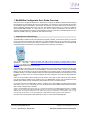
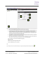
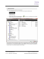
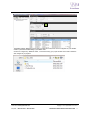
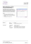
1 Mod/M-Bus Configurator User Guide Overview The function of the Configurator software is to allow users to configure the Modbus to M-Bus modules supplied by SyxthSense Ltd. The software will scan a port connected on your computer for a level converter that must first be connected to allow communications. This software will search the com ports ticked as shown and search for a range of addresses and baud rates to find your units. The software will then allow you to connect to the Module and associated MBUS Meters. In a test mode you can view the meters and add them into the device for continuous polling of data and conversion into the Modbus protocol for connection to a Modbus Master such as a Webserver or BMS system (e.g. SyxthSense SDC Sedona Controller). 1. Preparation for commissioning The MOD-M-BUS modules will talk to the software using RS232 or RS485. To allow this to operate you will need a level converter as most laptops use USB ports only. When configured with the correct drivers your computer will allocate your level converter a Port number. A suitable level converter is the ADAM-4561 1-port Isolated USB to RS-232/422/485 Converter which can support either protocol (via specific connections). You can also use RS232 to RS485 converters with USB to Serial converters. A suitable USB to Serial is SyxthSense GLT-2368 (http://www.syxthsense.com/software-and-systems/glt-2368/glt-2368-usb-to-serialconverter/). The RS232 to 485 converter must support auto hand-shaking. Suitable converter is B&B Electronics 485SD9TB RS232/485 Port Powered converter. The MOD-M-BUS unit requires a 24Vdc power supply before it can be used with this software, it will also need cable to connect the level converter to the MOD-M-BUS converter and also cable to connect to your MBUS Meter. Ensure all connections are as per the documentation prior to applying power. For the avoidance of doubt, the MBUS network is not polarity sensitive however the cable used must be suitable for the total length of run and the quantity of meters on the run. Contact SyxthSense for further information on the types of cable allowed for MBUS. Further to this the Modbus network design must also use the correct type of cable and the end of line devices must be terminated as detailed in the guidance notes. The MOD-M-BUS device must be allocated a unique Modbus device address and the network baud rate must also be known to conclude the set-up. If you have more than one MOD-M-BUS device to configure on the same Modbus LAN then please configure each device in turn on a 1:1 basis locally, do not try to add the device to the Modbus LAN until each device has been correctly configured and re-checked. Important: The MOD-MBUS units will not allow you to configure the addressing of the MBUS Meters themselves. The MBUS meters or devices must be allocated individual addresses prior to trying to configure the MOD-MBUS devices. This will need additional time and specialist software and tools. Please verify and have confirmation of the addresses prior to trying communicating with the meters. For help and equipment to configure MBUS Addressing please contact SyxthSense. For further help on planning the project please see the pre-com check sheet included appendix. Online Store: www.syxthsense.com Enquiries: T: 0844 840 3100 F: 0844 840 3200 Copyright 2013 SyxthSense Ltd. Ver 0.1 MoD-M-BUS CONFIGURATION S/W USER GUIDE 4