1
Wiring Example
9449
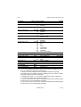
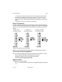
Figure 2. Keypad Addressing.
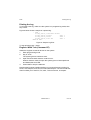
Keypad Backlight
When supplied from the factory the control unit is configured with the keypad
backlight ON. To turn the keypad backlight OFF remove the jumper from link
LK4, shown in Figure 2.
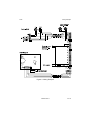
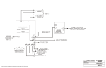
Wiring Example
Figure 3 shows an example system wired for two detectors. Note that mains
and battery connections are not shown.
Notes:
1. Power for detectors is available from two terminals on the control unit PCB
marked "+ - 12V AUX".
2. If you are not using an SAB, or wish to test the control unit with no SAB
connected, you must link 0V and TR on the control unit PCB.
4 of 16
496329 Issue 1