1
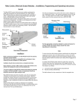
Sending an address from a single channel transmitter
Note
If a receiving unit, in set-up mode, does not receive a valid address within
3 minutes the receiver will automatically drop out of set-up mode.
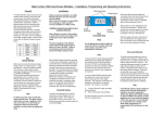
Room address
= 32+4=36.
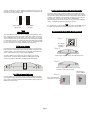
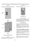
Fig 3.
Addressing Switches
Setting an address from a single channel wall switch
Once the addresses have been set it is strongly recommended to keep a
note of the settings and to keep these in safe place. Whilst it is easy to
set the addresses, those of the receiver units are normally only set once.
To do so requires access to the units and once set these may be installed
in inaccessible positions. If, therefore the wall-plate address get changed
for any reason and the original settings cannot be remembered then
access to the receiver units will be needed for reconfiguration.
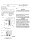
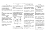
Step 1
Set address
switches on
controller
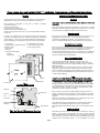
Setting receiver addresses.
Step 2
Once a House and Room number have been selected on a control panel
these need to be transmitted to each receiving module along with a valid
channel number. This is done by one of two methods using a Rako wall
switch , hand-held transmitter or Rako software RASOFT .
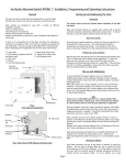
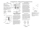
To send an address to a receiver unit, the unit needs to be put into
receive mode. To do this hold the magnet provided against the side
casing in the position indicated by the label and as shown below.
Magnet
House address
= 128+16=144
ROOM
128
64
32
16
8
4
2
1
From either a Rako single channel wall switch or hand-held transmitter
(both are functionally identical) press and hold both raise lower buttons
for 5 seconds. After 5 seconds the unit will automatically send a channel
1 address. The red LED on the transmitter will flash to confirm that this
has been sent. As soon as the receiver gets a valid address it
automatically drops out of set-up mode. To set other channel addresses
from 2 -15 RASOFT programming software is required
ON
BINARY VALUE
HOUSE
128
64
32
16
8
4
2
1
ON
BINARY VALUE
terminal screwdriver or similar device and carefully move some of the
switches into the ‘ON’ position. Addressing uses binary encoding and the
value of the switches is shown below.
Hold magnet against casing until LED illuminates
Magnet
Step 3
Remove magnet when LED starts to flash
Module is now in set-up mode
LED flashes to
confirm address
command is sent
Step 4
Fig 4. Set-up Magnet Positioning
Once the magnet is in the correct position an internal LED will illuminate.
If the magnet is held in position for approximately 5 seconds the LED will
start to flash, this flashing indicates that the module is ready to receive an
address from a transmitter.
Press and hold both
buttons for 5 seconds
Page 2