1
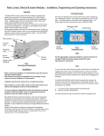
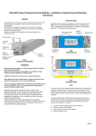
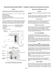
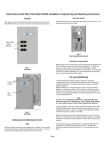
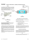
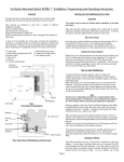
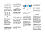
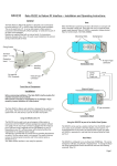
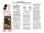
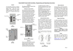
Rako RDA800 Installation, Programming and Operating Instructions
General
Rako RDA800 modules are dimmer units designed for use
with controllable fluorescent ballasts and LED drivers, or
any other suitable devices with control inputs for 0-10V,
DALI or DSI. RDA800 modules also have an internal relay
that switches the mains supply to the fitting.
RDA800 modules can be controlled by any Rako device
that transmits wireless RAKOM messages.
Before commencing installation of a Rako module please
read this instruction manual carefully. Rako Controls Ltd
accepts no responsibility for damage or injury caused by
incorrect installation of a Rako product.
Installation should only be carried out by a competent
electrician.
Never attempt to connect a Rako module or remove the
terminal cover without first isolating the circuit at the
fuse/MCB board.
The circuit supplying a Rako module should always be
protected by either a 5A fuse or 6A MCB.
Mounting
Rako modules should be mounted in areas that are
adequately ventilated, dry and outside of any enclosed
metal casings that may interfere with the wireless signal.
Wherever possible the mounting bracket should be used.
Connections
Connect the RDA800 module according to the wiring
diagram overleaf. Note that the control end of the module
has three sets of header pins and one connecting link. The
connecting link is used to select the appropriate control
output for the load, either 0-10V, DALI or DSI and is set on
0-10V as default.
Do not use loop In/Out connections within the module. A
junction box should be used if required.
Ensure the cable clamp bar securely clamps the cables and
that the terminal cover is fitted before switching the supply
on.
Initial Checks
When power is initially connected to the module the unit
should switch the load ON. The load can then be manually
switched using the clear button on top of the module.
The factory set address for both modules and transmitters is
House 1 Room 4 (See Fig 1 for further information). A
Rako wireless wallpanel set as address House 1 Room 4 will
control and dim the module.
Should the module not respond as above then further
investigation should be made before proceeding further.
Modules should be mounted vertically, with the terminals
at the bottom, or horizontally with the ventilation slots at
the top.
To avoid interference between neighbouring installations
chose a House address other than the factory default of
House 1 and set this on the transmitters using the House
address switches. Keep the House address the same
throughout the project (for master functions).
Chose a Room address for each separate room or area to be
controlled independently and set this on the appropriate
transmitters using the Room address switches. Note: Any
control panels set with the same address will act as two or
multi-way controls for the same Room.
The module now needs to be sent its new House and Room
address from the appropriate keypad. For rooms with
multiple modules each module needs to be also assigned a
separate Channel number from 1-15 within each Room.
The House and Room addresses are set using the switches
on the back of a Rako transmitter (see Fig 1) and the
Channel addresses are selected by putting a transmitter in
programming mode and ‘stepping’ through the channel
numbers (see Step 3 overleaf). This number is then 'sent'
(along with the House and Room address) to a receiver
(Step 5).
Notes on address switches
The address numbers are set using the switches on the back
of a Rako transmitter. Binary coding is used and a
diagrammatic explanation is given in Fig 1. It is not
however necessary to understand binary just set the House
switches to a different setting than the factory default and
use a different combination of Room switch settings for
each room or area to be controlled separately.
Whilst Rako modules are designed to be completely
maintenance free the units should be mounted in an
accessible location should there be a fault or re-addressing
of the unit be necessary (see 'Set-up and Addressing')
Loadings
Do not exceed the lesser of the two following values:
Relay output – Max 800VA
Control output – Max 25 devices.
Manual Addressing from Wallplate or Handheld
Before any lighting scenes can be programmed (see the
wall-panel or hand-held manual) the RDA800 module needs
to be addressed.
Fig.1
Set-Up and Addressing
RDA800 modules can be programmed manually or by using
RASOFT programming software. For software programming
refer to the appropriate programming guide supplied as a
PDF with the programming interface (RA or RTC-Bridge
etc.) or download from our website: www.rakocontrols.com.
Notes on Addressing
A dimmer will not receive an address of House 0 (All
switches set to off)
A dimmer will respond to, but not receive an address of
Room 0 (All switches set to off). This Room 0 address is
used for ‘Master House’ control
A dimmer cannot be set to channel 0.
To program a lighting scene see Wall panel or Hand held
manual.
Power-Up Mode
With the factory address setting of House 1 an RDA800
will turn ON when power is applied. When the House
address is changed the Power-Up mode becomes 'OFF'
which is generally preferred, for instance if there is a
power cut during a holiday.
Manual Operation
The clear button can be used as a manual On/Off
switch.
Fade Rate
An RDA800 module has a default fade rate of zero
making its response immediate. It maybe preferable to
have a delayed OFF rate when being used in
conjunction with dimming modules. The OFF fade rate
can be changed by using RASOFT programming
software or from a standard wireless 7 or 10 button
keypad.
To increase the fade rate from a 7 or 10 button wireless
keypad Press and Hold both the Off button and the
scene 1 button for approximately 5 seconds (the
wallpanel LED will start to flash) and then release the
buttons.
Multiple Control Panels
If the module is to be controlled by two wall or handheld transmitters it is only necessary to address the
module to one of these transmitters. Set the other
transmitters to the same House and Room address and
they will transmit exactly the same message as the first
transmitter and the module will respond accordingly.
LED functions
The internal LED behind the clear button will flicker
when the module receives ANY Rako wireless message
and is a useful diagnostic indicator. This function
becomes inactive after 20 minutes to avoid nuisance
light spill but can be re-activated by pressing the clear
button.
If an RDA800 module has already been addressed to a
wall-panel the internal LED will start to pulse as soon as
that transmitter (or any other transmitter with the same
address) is put into programming mode. The module
can still be re-addressed in the normal way, for example
when changing its Channel address within the same
Room.
Care and Maintenance
A Rako module contains no user serviceable parts.
Should for any reason you need to contact us please
contact us via our website www.rakocontrols.com or by
phoning our customer help line on 01634 226666.