1
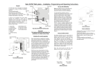
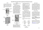
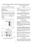
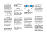
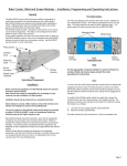
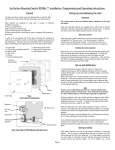
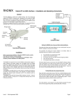
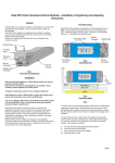
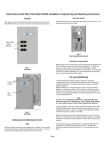
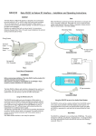
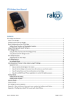
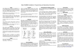
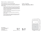
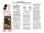
Rako RCP07 Wall-plates – Installation, Programming and Operating Instructions.
Rear Cover
Checking for correct operation
Universal backing
plate
Rako control panels are supplied with a pullout
tab to prevent inadvertent operation and battery
deterioration during transit. To remove this,
first remove the rear cover by inserting the tip of
a small screwdriver or similar into the prise point
(Fig. 2) and gently lift off the rear cover. This
should expose the battery compartment and
addressing switches. Care should be taken not
to touch or otherwise damage any of the
exposed electronic components.
Patress
PCB Retainer
Front Plate
Fig 1.
Front View of Components
With the rear cover removed pull out the tab
protecting the batteries (see Fig.2); your Rako
control panel should now be operational. To
check this press one of the buttons on the front
of the PCB retainer and the indicating LED
should illuminate briefly for a single flash. If the
LED does not flash or it flashes repeatedly for a
short burst (low battery warning) then you
should contact Rako controls on the number
given below.
Setting the address switches.
Each Rako transmitter has two, 8 way banks of
switches for setting its address. The two sets of
switches allow the user to choose from 256
house addresses and 256 room addresses. To
set the address, unclip the rear cover whereupon
the banks of switches will be now become
visible. To set an address, use a small terminal
screwdriver or similar device and carefully move
some of the switches into the ‘ON’ position.
Addressing uses binary encoding and the value
of the switches is shown below.
Note: Any control panels set with the same
address will act as two or multi way controls.
128
64
32
16
8
4
2
1
House address
= 128+16=144
128
64
32
16
8
4
2
1
ROOM
Important:
This Section should be read before the
installation of a Rako Control Panel
Special Addresses
ON
Aerial Cutouts
Fig 2.
Rear View of PCB Retainer and Rear Cover
2 x 6mm M3.5 screws.
2 x 25mm M3.5 screws.
2 x 12mm M3.5 screws.
2 x self-tapping screws
BINARY VALUE
1 x Front plate.
1 x PCB retainer
(complete with PCB
and button pad).
1 x Rear cover.
1 x Patress.
1 x Universal backing
plate.
HOUSE
In order to fit successfully into all the above
situations the wall-plate is made from an Addressing
assembly of parts, all of which are supplied as Switches
standard and are listed below. The parts can
also be identified from the drawing Fig1.
(Note: Depending on the application not all of
the parts may be used)
Addressing
Before installing a Rako wall panel the address
switches on the rear need to be set to an
appropriate House and Room address.
Setting an address is the way in which
interference between other Rako systems, either
with other rooms within your house or
neighbouring houses is avoided. It should be
remembered that with a booster unit a Rako
transmitter may have a range of over 100m.
Your Rako control panel comes set with a
default address of House 1 Room 4 and whilst
the unit will function with this address it is
strongly advised to select your own house
address and logical room addresses. Once set,
any receiver modules need to ‘learn’ the address
of the control panel/panels that they need to
respond to. To address a receiver module see
the module’s instruction manual.
ON
Batteries
The Rako RCP series of wall-plates are designed
to cope with a number of different installation
situations.
Pull-out
These are predominantly:
Tab
Flush fixing into a UK back-box.
Surface mounting with a UK back-box
Surface mounting with no back-box or onto a Prise
Point
European DIN standard or French box.
BINARY VALUE
General
Room address
= 32+4=36.
Fig 5.
Addressing Switches
House 0 (All switches set to off) is not a valid
address.
Room 0 (All switches set to off) is an overall
house master address. As a default this will act
as a master panel for any rooms in a house.
Pressing a button on a panel set at Room 0 will
be the same as pressing the same button on all
of the control panels within the house. This
function can only be disabled using the Rako
Rasoft programming software.
Using the Rako Rasoft programming software
every fourth room (4,8,12 etc) can be set as a
group master to control the subsequent 3
rooms, i.e. a Room 4 panel could control Rooms
5, 6 and 7. The functionality of this is similar to
the overall house control described above
whereby pressing a button on a group master
would have the same effect as pressing the
same button on the panels in the ‘slave’ rooms.
This function can only be enabled using the
Rasoft programming software.
Installation
Before assembly ensure that the rear cover is firmly
fixed and that the aerial is positioned in a way as to
not foul other components.
through the PCB retainer and into the bossed
inserts.
Surface fixing to European back-boxes.
Warning
Rako wall-plates are designed to operate at safety
extra low voltages (6V). When fixing the wallplates to existing back-boxes there may be mains
wiring present, if this is the case then the wiring
should be made safe, properly insulated and any
metal back-boxes earthed. Earthing of the back
box is essential if a decorative metal front plate is
being used. Should there be any doubt in how to
do this contact a qualified electrician.
Rako Controls Ltd accepts no responsibility for any
damage or injury caused by incorrect installation of
a Rako product.
For fixing to European DIN or French standard
back-boxes the Rako universal backing plate has
been designed so that two of the fixing slots
match European DIN standard back-box fixings
and two match standard French back-box
fixings. To mount the assembly, orientate and
mount the universal backing plate as applicable
(screws not provided) and then follow the
instructions for ‘Surface fixing with no backbox’. Care and maintenance
Surface fixing to UK back box.
Orientate the patress so that the bossed inserts are
aligned vertically and locate the PCB retainer in the
patress. Then using the 25mm fixing screws fix the
front plate to the retainer and patress and backbox.
Flush fixing to a UK back-box
Fit the PCB retainer in the back-box so that the
clear flange is flush to the wall. Then using the
12mm fixing screws (or 25mm if needed) secure
the front plate to the PCB retainer and back-box.
Note. If a metal front plate is being used, as per
the Rako RPP accessories, then the aerial must be
positioned outside of the back-box. This is
because the front plate and back-box will form a
screen for the radio signal, which will give very
poor radio transmitting conditions. To position the
aerial correctly a hole must be cut in the back-box
and a small diameter hole drilled into the wall.
Straighten the aerial and push the aerial into the
hole. The best radio transmission will be achieved
when all of the aerial fully extended and outside of
the back-box. If, because of physical constraints, it
is not possible to drill the hole in a position close to
where the aerial emerges from the PCB retainer,
then the rear cover can be removed and the aerial
re-positioned in a more convenient aerial cut-out
(see fig 2).
Surface fixing with no back-box
Take the universal backing plate and screw this to
the wall (screws not included) using the fixing
slots. Rotate the patress so that the bossed inserts
are aligned horizontally and then, using the 2 x
self-tapping screws, fix the patress to the universal
backing plate taking sure not to over-tighten the
screws. Insert the PCB retainer into the patress
and then using the 2 x 6mm fixing screws, secure
the front plate to the patress fixing the screws
Programming a Scene
Step 1
Chose the scene to be
re-programmed.
Put controller into
programming mode
by pressing and holding
the selected scene
button and both
raise and lower buttons
together
Rako thanks you for having purchased a Rako
product and hopes that you are pleased with
your system. Should for any reason you need to
contact us please contact us via our website
www.rakocontrols.com or by phoning our
customer help line on 0870-043-3905.
Step 2
LED starts to flash
after 5 seconds, panel
is now in programming
mode. Use buttons 1 & 2
to scroll through channels
one at a time.
When in programming
mode buttons have the
following functions
Battery replacement
The Rako RCP series of wall-plates are designed
to be powered by batteries. The designed
battery life is better than 3 years (based on 30
button presses daily) but the batteries will
eventually need replacing. In normal use the
Led on the front panel illuminates momentarily
when a button is pressed to indicate that a
(radio) transmission has been made. When the
batteries are approaching the end of their useful
life the Led will continue to blink after a button
has been pressed. When this starts to happen
the batteries should be replaced as soon as
possible.
Always use two CR2016
To replace the batteries unscrew the front plate
and remove the PCB retainer, taking care not to
damage the aerial (note that when flush
mounted the aerial may be located in a hole
outside the back-box). Remove the rear cover
and carefully slide out the batteries. Replace
with new batteries ensuring that the positive (+)
terminal makes contact with the battery clip and
the negative (-) terminal with the pad on the
circuit board.
To ensure reliable operation always ensure that
battery contacts and battery surfaces are kept
clean of any grease, moisture or other
contamination.
Warning
Lithium batteries may explode if handled
incorrectly. Always dispose of used batteries in
accordance
with
manufacturer’s
recommendations.
General
TIP
Press the
scene button first
Button
1
2
3
4
Off
Step 3
As each circuit flahes
in turn, use the raise
and lower buttons
to adjust lighting
to the desired levels
See details for scrolling
Button 1 scrolls up
through channels
1-15
Tip
If at any point it
is not clear which
is the current
circuit address
button 3 will
flash that circuit
without scrolling
on.
Step 4
Once levels are
set correctly for the
chosen scene. Save
any changes by
pressing button 4.
Circuits will all flash
to confirm.
Action
Scroll up and ident
Scroll down and ident
Ident only
Save changes
Exit programming
All circuits flash
to indicate channel 0
2
1
3
4
5
6
7
Scrolling
flashes each existing
circuit in turn
0
8
15
Button 2 scrolls
down through
channels15-1
9
14
13 12 11
10
Continue
incrementing
channels with button 1
to reach 0 or return using button 2
Step 5
Press Off button
to exit controller
from programming
mode.
To re-program another
scene repeat process
from Step 1