1
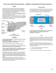
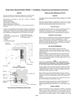
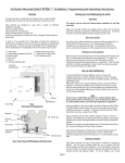
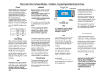
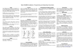
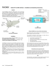
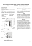
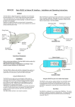
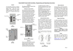
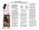
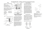
Three button Hand Held Transmitter RAH03 Installation, Programming and Operating Instructions.
General
Rear cover removal.
The rako three button hand held controllers are designed for use with the
Rako RACUB motor control units only with raise lower and stop functions.
Remove the rear cover by undoing the four fixing screws (see Fig.2) and
gently pulling the rear cover away.
Open/Close
/ Stop
buttons
Fig. 3
Rear View with cover removed
Checking for correct operation
With the rear cover removed pull out the tab protecting the batteries (see
Fig.3); the Rako transmitter should now be operational. To check this
press one of the buttons on the front of the PCB retainer and the
indicating LED should illuminate briefly for a single flash. If the LED does
not flash or it flashes repeatedly for a short burst (low battery warning)
then you should contact your Rako dealer.
Fig. 1
Front View
Set-up and Addressing
To avoid interference between adjacent rooms of a house and
neighbouring houses as well as allowing individual control of separate
curtains/blinds within a room Rako transmitters employ a structured
addressing system.
Rako transmitters use a structure based on house, room and channel
addresses. Using the two banks of DIL switches on the back of a wall
panel or hand control (see Fig.3) a House address can be selected from
one of up to 255 possible addresses and a Room address from one of up
to 255 possible addresses.
Fixing
screws
Rear
cover
Note
House 0 is not a valid address and Room 0 is a special address which
gives overall control for a whole house. Room 0 should not be selected
as a Room address without careful thought regarding the application.
Setting an address is the way in which interference between other Radio
Controlled Rako systems, either with other rooms within your house or
neighbouring houses is avoided. It should be remembered that a Rako
transmitter may have a range of over 100m.
Fig. 2
Rear View
Rako transmitters come set with a default address of House 1, Room 4,
Channel 1 and whilst the unit will function with this address it is strongly
advised that a specific and logical address for both House and Room be
selected
Setting Up and Addressing the Units
Note
Some advanced grouping arrangements are possible allowing banks of
modules to be controlled as groups within a room. Systems with
advanced programming need to factory set. For more details contact
Rako.
Rako hand-held transmitters are supplied with a pullout tab to prevent
inadvertent operation and battery deterioration during transit. To remove
this and to access the address switches remove the rear cover.
Page 1
From either a Rako single channel switch or transmitter (both are
functionally identical) press and hold both buttons for 5 seconds. After 5
seconds the unit will automatically send a channel 1 address. The red
LED on the transmitter will flash to confirm that this has been sent. As
soon as the unit gets a valid address it automatically drops out of set-up
mode.
Setting an address from a single channel contoller
Step 1
Room address
= 32+4=36.
Fig 3.
Addressing Switches
Set address
switches on
controller
Once the addresses have been set it is strongly recommended to keep a
note of the settings and to keep these in safe place. Whilst it is easy to
set the addresses, those of the receiver units are normally only set once.
To do so requires access to the units and once set these may be installed
in inaccessible positions. If, therefore the hand-held’s address is changed
for any reason and the original settings cannot be remembered then
access to the receiver units will be needed for reconfiguration.
Step 2
Magnet
House address
= 128+16=144
ROOM
128
64
32
16
8
4
2
1
Note
If a receiving unit, in set-up mode, does not receive a valid address within
3 minutes the receiver will automatically drop out of set-up mode.
ON
ON
128
64
32
16
8
4
2
1
BINARY VALUE
Each Rako transmitter has two, 8 way banks of switches for setting its
address. The two sets of switches allow the user to choose from 255
house addresses and 255 room addresses. To set the address, remove the
rear cover (refer to controller manual for details), whereupon the banks of
switches will be now become visible. To set an address, use a small
terminal screwdriver or similar device and carefully move some of the
switches into the ‘ON’ position. Addressing uses binary encoding and the
value of the switches is shown below.
HOUSE
Sending address from a single channel transmitter
BINARY VALUE
Setting an Address
Hold magnet against casing until LED illuminates
Setting receiver addresses.
Once a House and Room number have been selected on a control panel
these need to be transmitted to each receiving module along with a valid
channel number. This is done by one of two methods using a Rako wall
switch, hand-held transmitter or Rako software RASOFT.
.
Step 3
Remove magnet when LED starts to flash
Module is now in set-up mode
To send an address to a receiver unit, the unit needs to be put into
receive mode. To do this hold the magnet provided against the side
casing in the position indicated by the label and as shown below.
Step 4
Magnet
Press and hold both
buttons for 5 seconds
Fig 4. Set-up Magnet Positioning
Once the magnet is in the correct position an internal LED will illuminate.
If the magnet is held in position for approximately 5 seconds the LED will
start to flash, this flashing indicates that the unit is ready to receive an
address from a transmitter.
Page 2
LED flashes to
confirm address
command is sent
Operation
Single Channel Transmitters
Single channel transmitters only allow simultaneous control of all
channels in a room.
Care and maintenance
Battery replacement
The Silent Gliss series of transmitters are designed to be powered by
batteries. The designed battery life is better than 3 years (based on 30
button presses daily) but the batteries will eventually need replacing. In
normal use the LED on the front panel illuminates momentarily when a
button is pressed to indicate that a (radio) transmission has been made.
When the batteries are approaching the end of their useful life the LED
will continue to blink after a button has been pressed. When this starts
to happen the batteries should be replaced as soon as possible.
Always use two CR2016 type batteries.
To replace the batteries unscrew the front plate and remove the PCB
retainer, taking care not to damage the aerial (note that when flush
mounted the aerial may be located in a hole outside the back-box).
Remove the rear cover and carefully slide out the batteries. Replace with
new batteries ensuring that the positive (+) terminal makes contact with
the battery clip and the negative (-) terminal with the pad on the circuit
board.
To ensure reliable operation always ensure that battery contacts and
battery surfaces are kept clean of any grease, moisture or other
contamination.
Warning
Lithium batteries may explode if handled incorrectly. Always dispose of
used batteries in accordance with manufacturer’s recommendations.
NOTE
Early Versions of the RACUB are set up for Scene setting Latching mode
and may need to be reprogrammed using RASOFT to pulsing mode
Rako thanks you for having purchased a Rako product and hopes that
you are pleased with your system. Should for any reason you need to
contact us please contact us via our website www.rakocontrols.com or by
phoning our customer help line on 0870-043-39
Page 3