1
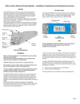
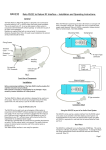
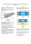
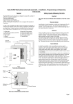
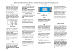
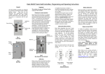
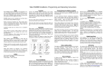
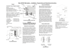
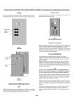
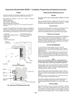
RADMX
Rakom RF to DMX Interface – Installation and Operating Instructions.
General
RAPSU
power
Supply unit
The Rako RADMX is a Rakom RF to DMX interface. The unit provides the
output of 8 DMX512 channels and is designed for the control of DMX
light fittings such as moving lights, colour changes and 3 colour LED’s.
The unit can be controlled and configured either using the RCP07 control
panels or from the RASOFT programming software.
Modules are supplied fitted with an internal aerial. For receiving distances
of greater than 15m the external aerial provided can be fitted.
DMX Output
terminals
Fixing Screws
+12V DC
0V
External Aerial
To be mounted at 90° to the direction of the receivers
COM
DATA +
DATA -
Terminal
Cover
Protective
Insert
Ext aerial &
PSU Terminals
Interface
Housing
Fig 2.
Connection Detail
Setting the RADMX room, house and Start channel addresses.
Fig 1.
Front View of Components
First select the Room and house address on your control panel. (see your
RCP07 installation instructions for details)
Installation
The procedure for setting the receiver address is as follows. Refer to
individual sections for details on each procedure.
Before commencing installation of the Rako RADMX interface module
first read this instruction manual carefully.
Rako Controls Ltd accepts no responsibility for any damage or injury
caused by incorrect installation of a Rako product.
The RADMX unit requires the use of the RAPSU external power supply. In
some instances this power supply can be derived from the fittings
themselves negating the requirement for the RAPSU (check with either
Rako or the fitting manufacturer). Connect the power supply and DMX
data as shown in Fig 2 opposite. Note that the connection terminals on
different fittings do vary and therefore make sure you have the relevant
connectors.
The RADMX is provided with an in built aerial so providing the distances
are within 15m the external aerial is not required. For greater distances
remove the internal aerial connection and fit the external aerial as
detailed in Fig 2.
The RADMX comes with the factory default settings as House 1, Room 4
and DMX channels 1 through to 8. To change these settings carry out the
following procedures:
•
•
•
•
•
Put wall-plate into programming mode.
Select the start channel number.
Put receiver into set–up mode using the magnet provided.
Press the ident button.
Exit programming mode on wall-plate.
The above ident function can be done from the RASOFT software without
using a wall panel. To do this put the receiver into set-up mode. Then
enter the relevant house and room address on the main screen. Select
the start channel number required and click the ident button. Once set
the receiver will automatically drop out of set-up mode.
Putting Wall-plate into programming mode.
Press and hold a scene button (one of the four numbered buttons on the
left hand side of the plate) and at the same time press and hold both the
raise and lower buttons (the right hand buttons). After 3 seconds the
LED will start to flash, the plate is now in programming mode. To exit
programming mode press the Exit button (see Fig. 4).
Note:
If the Exit button is not pressed or any other buttons pressed the panel
will exit from programming mode automatically after 3 minutes.
Issue 1 – 24th September 2003
Page 1
LED indicator
start channel address that it should respond to. If no more set-up
commands are to be sent by the wall-plate then press the Exit key to
return the panel to normal operating mode.
Start cycle button
Scene selection
and cycle stop
buttons
Rako start Channel Start Address = 1
Stop cycle and
lower buttons
Fig 3.
Wall-plate buttons in normal mode
Rako control
Channels
DMX Output
Channels
1 controls
2 controls
3 controls
4 controls
5 controls
6 controls
7 controls
8 controls
1 and 9 (0 second fade)
2 and 10 (0 second fade)
3 and 11 (0 second fade)
4 and 12 (0 second fade)
5 and 13 (0 second fade)
6 and 14 (0 second fade)
7 and 15 (0 second fade)
8 and 16 (0 second fade)
Channels 9-15 are not used for DMX
Channel
scroll up
Level up
Channel
scroll down
Ident
Level down
Store
Exit
Fig 4.
Wall-plate buttons in programming mode
Rako start Channel Start Address = 3
Rako control
Channels
DMX Output
Channels
3 controls
4 controls
5 controls
6 controls
7 controls
8 controls
9 controls
10 controls
1 and 9 (0 second fade)
2 and 10 (0 second fade)
3 and 11 (0 second fade)
4 and 12 (0 second fade)
5 and 13 (0 second fade)
6 and 14 (0 second fade)
7 and 15 (0 second fade)
8 and 16 (0 second fade)
Channels 1,2 and 11-15 are not used for DMX
Setting the start channel address
The first step is to find an available channel or group of channels for the
receiver. If you are controlling a 3 colour fitting for example then this will
require 3 channels of control. Once you set the first Rako channel address
remaining 7 channels will follow automatically. e.g. Rako start Channel at
1 will then utilise channels 1-8. Rako start channel 3 will utilise channels
3-10 etc. If you use a Rako start channel greater than 8 then you will not
have access to all of the DMX output channels since you only have 15
Rako Channels. The DMX output addresses will always be 1-8. There are
also DMX output channels 9-16 from the RADMX that have zero fades
that can be used for Gobos, Colour wheels etc, where you do not wish to
see all of the intermediate stages. These channels mirror the channels 18. (i.e. Changing channel 1 will also change channel 9, channel 2 will
change channel 10 and so on) This is better shown in fig 5 opposite.
Any of the RADMX channels not being used can still be used for other
receivers such as dimmers etc.
Rako recommends that wherever possible the start channel is set to 1.
To identify which channels already have allocated addresses first put the
wall-plate into programming mode. Then, using the Channel scroll up
and Channel scroll down keys scroll through the 15 available channel
addresses. When a channel address is reached that is already allocated,
that channel output will flash in a slow double pulse to identify itself.
Channel 0 will flash all the channels in a fast quadruple flash indicating
the start point (note: it is not possible to program the RADMX to start
channel 0). Scroll through until you find an available channel i.e. a
channel where no output flashes, or to another specific channel that you
wish to set the receiver to and then stop. This is the channel identity that
will be sent to the receiver when the Ident key is pressed. Next put the
receiver into set-up mode (see putting receiver into set-up mode) and
then press the Ident button. The receiver will flash its load to
acknowledge receipt of the command and then automatically drop out of
set-up mode. The receiver has now registered the house, room and the
Rako start Channel Start Address = 10
Rako control
Channels
DMX Output
Channels
10 controls
11 controls
12 controls
13 controls
14 controls
15 controls
N/A
N/A
1 and 9 (0 second fade)
2 and 10 (0 second fade)
3 and 11 (0 second fade)
4 and 12 (0 second fade)
5 and 13 (0 second fade)
6 and 14 (0 second fade)
7 and 15 (0 second fade)
8 and 16 (0 second fade)
Channels 1-9 are not used for DMX
Fig 5
Examples of start channel addresses and how this relates to Rako
channel and DMX outputs.
Putting receiver into set-up mode.
The RADMX is put into set-up mode using the magnet method as
follows:
Firstly ensure that the receiver has been connected correctly
Page 2
Then using the small magnet provided with each receiver, press the
magnet against the receiver casing just over halfway down (see Fig.6).
The approximate position for this is indicated by the ‘magnet point’
legend on the top label. When the magnet is in the correct position an
internal LED will illuminate. The LED will stay on with a steady
illumination all the time that the magnet is in the correct position. Hold
the magnet in this position for 3 seconds until the LED starts to flash.
The receiver is now in set up mode.
Magnet
Approximate position for Rako
programming magnet.
Fig 6
Fade Times and Scene Cycling
Fade times are set using the RASOFT software. As with the Rako
dimmers, different fade times can be set for different channels allowing
the user to create some interesting effects.
Open RASOFT and select the Controls menu, then go to Fade Times.
Select the channel you wish the fade time to be applied to and adjust the
time to suit. Performing the above function with the ‘All’ selected will
change the fade rates of all the channels.
Note: the fade time is changed instantly without selecting the store
function. To return the RADMX to its factory settings hit the “reset
Defaults” button.
The Cycle routine is started using the “raise” button on the control panel.
This begins cycling continuously around scenes 1-4. It will begin fading
from one scene to the next once all of the channels have finished fading
to the last scenes preset levels. The cycle can be stopped using any of the
other buttons on the control panel (see fig 3)
Your RADMX is now ready for operation.
Rako thanks you for having purchased a Rako product and hopes that
you are pleased with your system. Should for any reason you need to
contact us please contact us via our website www.rakocontrols.com or by
phoning our customer help line on 01634 226666.
Page 3