1
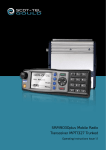
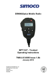
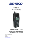
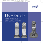
SRM9022
Mobile Radio
Trunked MPT
Operating Instructions
TNM-U-E-0068 Issue 2
May 2006
TMC Radio Pty. Ltd.
1270 Ferntree Gully Road
Scoresby
Victoria, 3179
Australia
ISO9001 Lic.QEC20848
SAI Global
SRM9022 ~ TMR MOBILE RADIO USER GUIDE
ASSOCIATED DOCUMENTATION
The following documentation is available for use with the SRM9000 series of
products:
TNM-I-E-0005
TNM-M-E-0001
TNM-U-E-0012
TNM-U-E-0013
TNM-U-E-0003
TNM-U-E-0004
TNM-U-E-0065
SRM9000 Series Installation Instructions
SRM9000 Service Manual
SRM9020 Trunked Operating Instructions
SRM9020 PMR Operating Instructions
SRM9030 PMR Operating Instructions
SRM9030 Trunked Operating Instructions
SRM9022 PMR Operating instructions
To order copies of any of the above publications, or any other TMC Radio product,
contact TMC Radio on +61 3-9730-3800 or send a Fax on +61 3-9730-3968.
ABOUT THIS DOCUMENT
This publication is copyright and no part may be reproduced without prior permission
of TMC Radio.
Due to our policy of continuous improvement to our products and services, technical
specifications and claims, correct at time of publication, may be subject to variation
without prior notice.
TMC Radio has endeavoured to ensure that the information in this document is fairly
and accurately stated, but does not accept liability for any errors or omissions.
© TMC Radio 2006
page 2
TNM-U-E-0068 Issue 2
SRM9022 ~ TMR MOBILE RADIO USER GUIDE
SAFETY
1. Do NOT operate your radio, without a handsfree kit, whilst driving a
vehicle.
2. Do NOT operate your radio in an explosive atmosphere.
Obey the 'Turn Off Two-way Radios' signs where these are posted, e.g.
on a petrol station forecourt.
3. Do NOT touch the antenna while the radio is transmitting.
4. Do NOT operate the radio if the antenna has become disconnected or
damaged.
HINTS FOR USING THE RADIO
•
•
•
•
When speaking, hold the microphone a few centimetres from your mouth and
speak across it, rather than into it.
Keep the length of your conversation to a minimum and replace the microphone
on its cradle after use.
When it is possible to move location, avoid making calls from known poor signalstrength areas such as the radio systems fringe areas (limit of range) or from
screened or shadowed areas, e.g. an underground car park or underpass.
To avoid unnecessary drain on the vehicle battery, keep the engine running when
using the radio for extensive periods of time.
© TMC Radio 2006
page 3
TNM-U-E-0068 Issue 2
SRM9022 ~ TMR MOBILE RADIO USER GUIDE
CONTENTS
1.
INTRODUCTION..................................................................................................6
1.1
Overview ......................................................................................................6
1.2
Installation ...................................................................................................6
1.3
Conventions ................................................................................................6
2.
FRONT PANEL CONTROLS...............................................................................7
3.
MENU SYSTEM ...................................................................................................8
3.1
4.
5.
Menu navigation..........................................................................................8
MAIN MENU SCREENS ....................................................................................10
4.1
Phonebook Screen....................................................................................10
4.2
Stored Calls Screen ..................................................................................11
4.3
Recall Screen.............................................................................................13
4.4
Status Screen ............................................................................................13
4.5
Call Types Screen .....................................................................................14
4.6
Setup Screen .............................................................................................14
COMMON FUNCTIONS AND FACILITIES .......................................................15
5.1 Switch-On/Switch-Off ...............................................................................15
5.1.1
In-Service Indication ................................................................................15
5.1.2
Volume Adjustment .................................................................................15
6.
CALL TYPES.....................................................................................................16
6.1 Making a Voice Call...................................................................................17
6.1.1
During a Voice Call..................................................................................17
6.2 Making a Status Call .................................................................................18
6.2.1
Using the Phonebook ..............................................................................18
6.2.2
By Dialling the Numbers ..........................................................................18
6.3 Receiving a Call.........................................................................................19
6.3.1
Receiving a Voice Call.............................................................................19
6.3.2
Receiving a Group Voice Call..................................................................20
6.3.3
Incoming Status and Data Messages ......................................................20
6.4 Call Diversion ............................................................................................21
6.4.1
From the Call-Types Screen....................................................................21
6.4.2
By Dialling the Numbers ..........................................................................21
6.4.3
To Cancel a Diversion .............................................................................21
6.5
7.
DTMF Operation ........................................................................................22
SETUP ...............................................................................................................23
7.1 Setup Sub Menus ......................................................................................23
7.1.1
User Options............................................................................................23
© TMC Radio 2006
page 4
TNM-U-E-0068 Issue 2
SRM9022 ~ TMR MOBILE RADIO USER GUIDE
7.1.2
7.1.3
7.1.4
7.1.5
7.1.6
7.1.7
8.
9.
Group ......................................................................................................24
Phone Book Edit Menu............................................................................24
Contrast...................................................................................................26
Alert Volume ............................................................................................26
Information...............................................................................................27
Network ...................................................................................................27
OPTIONS ...........................................................................................................28
8.1
Quick Release Transceiver Kit.................................................................28
8.2
Microphone/Control Head Extension Lead .............................................28
8.3
Parallel I/O Expansion Option (dmap) .....................................................28
8.4
Internal GPS Option ..................................................................................28
8.5
Cross-linked Cable....................................................................................28
8.6
600 Ohm Interface Option.........................................................................28
8.7
Dual Control Head Option (dmap) ...........................................................28
8.8
Dual Transceiver Option (dmap)..............................................................28
8.9
Desk Top Base Kit.....................................................................................28
TROUBLESHOOTING.......................................................................................29
© TMC Radio 2006
page 5
TNM-U-E-0068 Issue 2
SRM9022 ~ TMR MOBILE RADIO USER GUIDE
1. INTRODUCTION
1.1
OVERVIEW
The SRM9000 Series Radios are versatile Digital Signal Processor (DSP) controlled,
two-way mobile radios. The SRM9000 Series is available in a number of frequency
bands and versions for specific applications. This manual describes the operation of
the SRM9022 TMR Controller Microphone variant.
The radio consists of a Transceiver unit that may be mounted in the vehicle boot or
under a seat, and a Controller Microphone, which is designed to mount on the
vehicle console or within view and reach of the operator.
The radio is software programmable and can be customised to the operational
requirements of your particular fleet. Your TMC Radio representative can help in
programming your radio facilities to meet your present and future requirements.
This guide describes the facilities that are currently available and can be
programmed into the SRM9022.
1.2
INSTALLATION
As the installation of your SRM9022 Radio is a technical and possibly hazardous
operation, we recommend that it is installed and set up for use by your dealer or an
authorised installer. However, if you need information regarding the correct
procedures for installation, please refer to the SRM9000 Series Installation
Instructions supplied with the radio.
1.3
CONVENTIONS
Where the word “generally” or “may” is used to describe a facility, this operation is an
option that may be enabled with the Radio Field Personality Programmer (FPP).
© TMC Radio 2006
page 6
TNM-U-E-0068 Issue 2
SRM9022 ~ TMR MOBILE RADIO USER GUIDE
2. FRONT PANEL CONTROLS
Volume Up/Down
Microphone
Function #5 (F5)
Function #6 (F6)
RX/TX LED
Push To Talk
Power On/Off
John Smith
In Service
Down or
Function #2 (F2)
Up or
Function #3 (F3)
Menu or
Function #1 (F1)
OK or
Function #4 (F4)
Figure 2-1 SRM9022 Controller Mic. Key Layout
© TMC Radio 2006
page 7
TNM-U-E-0068 Issue 2
SRM9022 ~ TMR MOBILE RADIO USER GUIDE
3. MENU SYSTEM
The SRM9022 radio software uses a programmed Menu structure to enable the
operator to access all of the radio options. The structure of the menu (comprising up
to thirteen screens) can be programmed to meet the specific needs of individual
customers. Figure 2 illustrates a complete menu structure of the radios capabilities.
Any or all of the Screens can be programmed or hidden with the following provisos:
The Phone Book Screen is always the default Screen displayed.
The Main Menu provides access to the usual Screens required to operate the radio.
The Setup Sub Menus provides access to the radios setup parameters.
When options are placed in a Setup sub-menu, Setup should be defined as one of
the selections in the Main Menu.
Both the Main Menu and the Setup sub-menus can each hold up to ten Screens.
Programming can allow any menu to be in any position.
3.1
MENU NAVIGATION
The / keys are generally used to navigate through menus, or increase/decrease
a value.
© TMC Radio 2006
page 8
TNM-U-E-0068 Issue 2
SRM9022 ~ TMR MOBILE RADIO USER GUIDE
Menu System
OK
OK Key
'M'
'M' Key (same as ’BACK’)
Up Key
Note: Example Menus only shown.
Other Menus may be configured with the FPP
Down Key
MPT1327 TNK Menu rev2
'M'
'M'
SETUP
Menu
'M'
NETWORK.
Menu
NETWORK
OK
OK
'M'
'M'
RADIO INFO.
Menu
RADIO
INFORMATION
OK
'M'
'M'
STATUS
Menu
'M'
STATUS
'M'
ALERT VOL.
Menu
OK
ALERT
VOLUME
OK
'M'
'M'
CONTRAST
Edit Menu OK
CONTRAST
'M'
'M'
RECALL
Menu
RECALL
'M'
Edit Menu OK
OK
'M'
'M'
GROUP
Menu
'M'
CALL
TYPES
Menu
'M'
PHONEBOOK
'M'
'M'
User Options
OK
GROUP
OK
'M'
CALL
TYPES
PHONEBOOK
OK
KEY BEEPS
ON/OFF
SubMenu Selections
'M'
STORED
CALLS
Menu
BACKLIGHT
ON/OFF
'M'
STORED
CALLS
OK
DTMF
ON/OFF
'M'
PHONE
BOOK
Scroll through
Phonebook
Entries
ENTRY POINT
Default Screen
Figure 2 - Menu Navigation
© TMC Radio 2006
page 9
TNM-U-E-0068 Issue 2
SRM9022 ~ TMR MOBILE RADIO USER GUIDE
4. MAIN MENU SCREENS
4.1
PHONEBOOK SCREEN
The Phonebook allows calls to be made to entries from the Phonebook list.
The Name Field shows
the current selected entry
from the Phonebook.
The RSSI Bars indicate
the signal strength of the
current Control or Traffic
channel.
John Smith
In Service
M
Displayed Labels show the
function of the F1& F4
buttons. Pressing one of
these buttons will execute
the function.
The
/
The ICON Line displays
various icons as
described
in the table below.
The Message Line
provides information about
what the radio is doing, e.g.
Call-setup, Queued,
Diverted, etc.
buttons may be pressed to scroll through the Name Field entries.
Press the OK (call) key to call the Name Field entry.
The Keypad may be used to enter dialstrings directly.
Several Icons can be displayed as shown below:
ICONS
INDICATION
The rotating arrow icon shows that the radio is registering with the Trunk
Network. It disappears when the radio is in-service.
*
The envelope icon indicates that there are one or more stored calls, (in
the Stored Calls menu).
The outline speaker icon indicates that speaker audio is muted, e.g.
during Call Setup, NPDs, etc.
The solid speaker icon indicates that speaker audio is enabled, eg
during a Call.
This icon indicates Call Pending, i.e. there is an outgoing call waiting for
the radio to be In-Service.
© TMC Radio 2006
page 10
TNM-U-E-0068 Issue 2
SRM9022 ~ TMR MOBILE RADIO USER GUIDE
4.2
STORED CALLS SCREEN
This screen allows missed Voice calls (and received Status and Data messages) to
be reviewed.
The * icon will show in the Main Phonebook Screen when there is an entry in this
Screen. A "Bip" tone is emitted every few seconds when a new call or message is
stored.
Three different types of call can be stored. The screen display will change
depending on the type of call stored.
Missed Voice Call
John Smith
Voice
M
Received Status Message
Caller
Message
M
Received Data Message
John Smith
The address is...
M
© TMC Radio 2006
page 11
TNM-U-E-0068 Issue 2
SRM9022 ~ TMR MOBILE RADIO USER GUIDE
The displayed number (#05) shows the queued position of the entry.
The most recent call is shown whenever this Screen is displayed.
Press
/
buttons to scroll through other stored calls.
Press the F6 to return to the Phonebook Screen without making a call.
Press OK key to bring up a popup menu with functions:
More
John Smith
The address is...
M
The address is 27 Harold
Street Scoresby.
Pick up after 10am.
M
Delete the message and go
to stored calls screen.
Exit: Go to idle screen
Press M to make the popup disappear.
© TMC Radio 2006
page 12
TNM-U-E-0068 Issue 2
SRM9022 ~ TMR MOBILE RADIO USER GUIDE
4.3
RECALL SCREEN
Use this Screen to review any of the last eight recently placed calls.
•
Press the / buttons to scroll
through the Recall list.
•
Press OK and select “Exit” to return to
the Phonebook Screen without
making a call or press back twice.
•
Press OK and select “Delete” to
delete the viewed entry and return to
the Recall Screen.
•
Press OK and select “More” to go to
the Phonebook Screen with the Call
Dialstring ready for editing, the
keypad is enabled for this step.
M
4.4
STATUS SCREEN
Use this Screen to view and send Status Messages from the programmed list.
The screen will always open at the last viewed message.
•
Press the / buttons to scroll
through the Status list.
•
Press the F6 to return to the
Phonebook Screen without making a
call.
•
Press OK to go to the Phonebook
Screen with the Status Message
Dialstring ready for editing, the
keypad is enabled for this step.
© TMC Radio 2006
page 13
Gone Home
* 01 *
M
TNM-U-E-0068 Issue 2
SRM9022 ~ TMR MOBILE RADIO USER GUIDE
4.5
CALL TYPES SCREEN
Use this Screen to make different types of calls.
•
Press the / buttons to scroll
through the available call types.
•
Press the F6 to return to the
Phonebook Screen without making a
call.
•
Press OK to go to the Phonebook
Screen with the Call-Type modifier
ready for editing, the keyboard is
enabled for this step.
Conference
*1*
M
4.6
SETUP SCREEN
Use this Screen to access the other Setup submenus.
•
Press OK and the /
show the submenus.
buttons to
Setup
See Section 7 for further information.
© TMC Radio 2006
page 14
M
TNM-U-E-0068 Issue 2
SRM9022 ~ TMR MOBILE RADIO USER GUIDE
5. COMMON FUNCTIONS AND FACILITIES
5.1
SWITCH-ON/SWITCH-OFF
• Momentarily press the On/Off/Volume button
to switch the radio ON.
•
The display will illuminate and show a
‘Welcome Message’ and the Trunk Identity of
the radio.
•
After a brief time the display will revert to the
Phonebook Screen, at which time the radio is
ready for use.
•
Pressing and holding the On/Off knob for
approximately 2seconds will switch the radio
Off.
•
If the radio Inactivity Timer is enabled, the
radio will automatically turn Off after several
hours of inactivity (i.e. no buttons pressed).
The radio will emit warning beeps for 10
seconds prior to switching off. Pressing any
button will reset this timer.
•
The radio can also be setup to switch on
automatically with the Vehicle Ignition
whenever the vehicle is started.
Welcome Msg
201-2001-20
M
John Smith
In Service
M
5.1.1 In-Service Indication
• After switch on, the radio must 'Register' with
the Trunking Network before it can place or
receive calls. When the radio is searching for
the best channel a rotating arrow and the
signal strength of the scanned channel is
displayed. When the radio has registered, the
rotating arrow symbol will disappear.
•
The radio is said to be IN SERVICE when it is
in contact with the Network, and the arrow
symbol is not displayed. A call cannot be
made until the radio is IN SERVICE. The
radio can queue one call, which will be made
as soon as the radio gains service.
John Smith
No Service
M
5.1.2 Volume Adjustment
The Volume Control adjusts the speech level at the loudspeaker. The (+) button on
top of the controller increases the volume and the (-) button decreases the volume.
Note: The radio can be programmed so that the volume cannot be turned off
completely.
© TMC Radio 2006
page 15
TNM-U-E-0068 Issue 2
SRM9022 ~ TMR MOBILE RADIO USER GUIDE
6. CALL TYPES
The Trunking System allows the user to make a number of different types of call.
The SRM9022 supports most of the call types that can be accessed through the
Trunk Network, including:
Voice calls between Individuals or Groups
Include Calls
Status Calls
Priority and Emergency Calls
Diversion Calls
Broadcast Calls
Individual Calls. Allow private conversations between two users. Other users can
be included in the call using an Include Call.
Group Calls. Allow a group of users to participate in a group conversation. Any
participant in the group can leave the call individually, but only the originator can end
the call.
Status Calls. Allow a status number to be sent between users. The SRM9022
allows text messages to be associated with up to 30 status numbers and can display
these text messages when such a status is to be sent or is received.
Diversion Calls. Allows the user to divert incoming calls to another radio, telephone,
etc. For example, when away from their vehicle, a user can divert calls to the depot
radio.
Normal, Priority and Emergency Calls. If the channel is busy, Normal calls are
placed in a queue and actioned when they reach the top of the queue. Priority calls
jump to the top of the queue unless a previous priority call is taking place.
Emergency calls are actioned immediately.
Broadcast Calls. Are similar to Group calls except that only the person who makes
the call can speak to the other parties in the call.
Notes
1: Some of these call types are only available after prior arrangement with
the Network Operator.
2: Most Trunk Networks have a time limit placed on call duration. The
Network terminates the call after this time.
© TMC Radio 2006
page 16
TNM-U-E-0068 Issue 2
SRM9022 ~ TMR MOBILE RADIO USER GUIDE
6.1
MAKING A VOICE CALL
Voice Calls may be made in several different ways:
Using the Phonebook :
•
From the Phonebook Screen, scroll through the entries using the / buttons
until the desired name is shown; then press the OK button (F4 must be
programmed as “Call” function).
Using Direct-Call Function Button:
•
The F1…6 buttons may be assigned as Direct-Call buttons. Pressing such a
button will place a call to the pre-programmed identity. e.g. Depot in above
example.
Keypad Entry:
•
The Users ID number can be entered directly as a dialstring using the Keypad.
e.g. 45# will call radio unit No 45.
•
Dialstrings of up to 30 digits can be used, refer to Appendix B. for numbering
convention and valid dialstrings.
Quick-Dial Memories:
•
The first 20 phone Book Entries (0-19) can be setup as twenty Quick-Dial
Memories.
•
These allow a dialstring for a call number to be dialed quickly using the keypad to
enter the memory number followed by # e.g. 12# will dial the number in Memory
12. The Phone Book Edit facility allows these numbers to be changed.
6.1.1 During a Voice Call
When a call is placed, a Call Progress Message is displayed on the Message Line
and the speaker emits Call Progress tones (See Appendix A for more details).
When the called radio is contacted, both radios will “ring” and display the call setup
icon.
When the called person answers, both radios will be connected and will display the
audio enabled icon.
A conversation can now take place by each operator, in turn, pressing their
Microphone PTT buttons and speaking.
When the call is finished, either operator can end the call by:
•
Replacing the Microphone on its bracket
•
Pressing the F6 button.
Note: If the called radio cannot be contacted (radio off or out of range) or does not
answer within a short period of time (dependant on the Network - about 10-30
seconds), a Radio Busy or Unavailable message is displayed and call-fail
tones are emitted.
© TMC Radio 2006
page 17
TNM-U-E-0068 Issue 2
SRM9022 ~ TMR MOBILE RADIO USER GUIDE
6.2
MAKING A STATUS CALL
Status Calls allow a Status Number to be sent between users. This “status number”
can have a meaning that the user assigns to it.
e.g.
1
2
14
may mean: “On the Job”
may mean: “At Lunch”
may mean: “Contact Home”, etc.
A Status Message can be sent in a number of ways similar to making Voice Calls.
6.2.1 Using the Phonebook
To send a Status Call using the Phonebook:
Scroll through the Phone book until the persons name is displayed (or enter the ID
number using the Keypad).
Do NOT press #.
Go to the Status Screen.
Then use the
displayed.
/
buttons to scroll through the entries until the desired message is
Press the PTT button to send the Status Message to the selected Phonebook
person (or entered number).
Note: Your radio may be set up to send all Status Messages to a fixed identity.
6.2.2 By Dialling the Numbers
If the Status Message Number and the destination ID Number are known, use the
keypad to enter the numbers in the format
*0n*x#
where
e.g.
If Status 2 (“At Lunch”) is to be sent to Andrew Jones (Identity 35) :
Enter
n is the Status Message Number, and
x is and the destination ID Number
*02*35#
Note: You cannot send a Status Message during a Voice Call.
© TMC Radio 2006
page 18
TNM-U-E-0068 Issue 2
SRM9022 ~ TMR MOBILE RADIO USER GUIDE
6.3
RECEIVING A CALL
The SRM9022 will respond to incoming calls according to the type of call being
received.
There are three types of call:
•
Voice Call.
•
Group Voice Call.
•
Status Message or Data Message.
6.3.1 Receiving a Voice Call
When a call is received the radio will ring and display the call setup icon
origin of the call.
and the
While the radio is ringing, the user can answer the call:
•
By pressing the Microphone PTT button
•
By removing the Microphone from its bracket.
When you answer the call, both radios will be connected and will display the audio
enabled icon.
A conversation can now take place by each operator, in turn, pressing their
Microphone PTT buttons and speaking.
When the call is finished, either operator can end the call by:
•
Replacing the Microphone on its bracket, or
•
Pressing the F6 button.
If a ringing call is not answered before the Network times out, or the Caller cancels
the call, details of the call are entered in the Stored Calls Screen, refer to Section 4.2.
Notes:
1. The SRM9022 responds in the same manner as above for Priority and
Emergency calls. Emergency Calls show Emergency on the display.
2. Some Trunking Networks provide a different Call-Set-Up method which
allows the radios to automatically answer incoming Voice Calls or
allows the Caller to speak to the called person while the radio is ringing.
© TMC Radio 2006
page 19
TNM-U-E-0068 Issue 2
SRM9022 ~ TMR MOBILE RADIO USER GUIDE
6.3.2 Receiving a Group Voice Call
A Group Voice Call differs from an individual call in that the operators do not answer
the call. All radios that are members of the Group automatically connect to the group
call.
While in a Group Call, all operators can PTT, in turn, and talk to each other. Only the
Originator can Clear the call. Any operator can leave the Group Call in the same
manner as ending a normal voice call, refer to Section 6.3.1.
Notes:
1.
In some Trunk Networks, operators who leave a Group Call are
returned to that Group Call after a short period of time. This “Late
Joiner” Network facility allows users that were previously engaged on
another call, to join a Group Call that is in progress.
2.
A Broadcast Call is a special type of Group Call in which only the
originator can speak. All other group members are inhibited.
Broadcast calls are originated using dialstrings entered on the
keypad, refer to Appendix B.
6.3.3 Incoming Status and Data Messages
Incoming Status and Data Messages are stored, and can be viewed, in the Stored
Calls Screen, refer to Section 4.2.
If not already displayed, the
icon appears on the Main Phonebook Screen and a
short ‘bip’ is emitted every 5 seconds to alert the user that a new message has been
received.
© TMC Radio 2006
page 20
TNM-U-E-0068 Issue 2
SRM9022 ~ TMR MOBILE RADIO USER GUIDE
6.4
CALL DIVERSION
Incoming calls can be diverted to another radio, telephone, or PABX extension, using
the Call Diversion facility provided by the Trunk Network. In many instances Call
Diversion is only available after prior arrangement with the Network Operator.
A diversion may be set up via the Call-Types Screen or direct from the keypad.
6.4.1 From the Call-Types Screen
Scroll through the Phonebook until the persons name is displayed (or enter the ID
number using the Keypad).
Do NOT press #.
Go to the Call-Types Screen, then use the
entries until “Divert” is displayed.
/
buttons to scroll through the
Press OK button to make the diversion to the selected Phonebook person (or
entered number).
6.4.2 By Dialling the Numbers
If you know the destination Identity Number, use the keypad to enter the numbers in
the format:
*41*n#
where
n is the destination ID Number
e.g.
*41*23#
*41*097303800#
diverts to unit 23.
diverts to a telephone number
6.4.3 To Cancel a Diversion
You cancel a call diversion by typing the dialstring #41#, or by selecting the “Cancel
Divert” option from the Call-Types Screen and pressing the OK button.
Note: Other dialstrings for Call Diversion are as follows:
DIALSTRING
FUNCTION
*41*n#
Divert both Voice and Data calls
*411*n#
Divert only Voice calls
*412*n#
Divert only Data calls
#41#
Cancel both Voice and Data diversions
#411#
Cancel only Voice diversions
#412#
Cancel only Data Diversions
These dialstrings can be stored in the Phone Book.
© TMC Radio 2006
page 21
TNM-U-E-0068 Issue 2
SRM9022 ~ TMR MOBILE RADIO USER GUIDE
6.5
DTMF OPERATION
When the DTMF facility is enabled, (refer to Section 7.1.1), the keypad is
automatically switched to DTMF mode whenever a Voice Call occurs. In this mode
you can send DTMF tones for activating functions via a Voice Call or telephone
connection.
Tones are generated using the keys 0…9 * and #.
Note: When DTMF is enabled, the keypad cannot be used to make Include calls.
© TMC Radio 2006
page 22
TNM-U-E-0068 Issue 2
SRM9022 ~ TMR MOBILE RADIO USER GUIDE
7. SETUP
The Setup sub-menus allow the operator to edit/modify the operation of some of the
general functions of the radio. The programmer can restructure or restrict access to
any or all of these menu screens and may rearrange them according to specific
requirements.
7.1
SETUP SUB MENUS
The Setup sub-menu structure programmed at manufacture is shown in Figure 2.
These sub-menu Screens provide access to operator functions as follows.
User Options
Key beeps, Display Illumination & DTMF on/off
selection.
Group
Groups 1 - 8 Fixed groups,
Groups 9 - 16 Network Dynamic,
Groups 17 -24 Operator Editable.
Phone Book Edit
Allows Phonebook entries to be added, deleted or
changed.
Contrast
Display contrast adjustment.
Alert Volume
Beep tone level setting (relative to Audio Volume).
Information
Programmer File description, SW version, Trunk ID and
Radio Serial No.
Network
Trunk Network-1/2 or Conventional Channel selection.
7.1.1 User Options
• The User Options menu allows the Keybeeps,
Display illumination and DTMF facilities to be
set On or Off.
•
Use the / buttons to scroll between the
different facilities.
•
The OK button toggles the selection On/Off.
The setting is saved on exit.
© TMC Radio 2006
page 23
Key Beeps
ON
M
TNM-U-E-0068 Issue 2
SRM9022 ~ TMR MOBILE RADIO USER GUIDE
7.1.2 Group
Use the Group menu to view groups of which you are a member. The lowest
numbered Group ID will be displayed
•
Use the
Groups.
•
Groups 1 to 8 have been set up by the
programmer and cannot be changed by the user.
•
Groups 9 to 16 are User Defined via the * 50 *… to
* 57 *… keypad dialstrings.
•
Groups 17 to 24 are dynamically assigned by the
Trunk Network and cannot be changed by the
user.
•
/
buttons to scroll the available
123456789
M
Use the (OK) button to return to the idle
Phonebook screen.
7.1.3 Phone Book Edit Menu
This menu allows you to add, edit or delete a Phone Book entry.
7.1.3.1 ADD A NEW ENTRY
•
From the main Phone Book Edit Screen (at any
Phonebook Entry), just press OK.
Use the
/
buttons to select “Add” and press OK.
Enter the new Entry number using the keypad…
© TMC Radio 2006
page 24
…and press OK.
TNM-U-E-0068 Issue 2
SRM9022 ~ TMR MOBILE RADIO USER GUIDE
Next, enter new Entry text using the ABC keypad (see
7.1.3.4 below), …
…and press OK again to exit
back to the Idle Screen.
7.1.3.2 DELETE AN ENTRY
Use the / buttons to select the required
Phonebook Entry, then press OK.
Use the / buttons to select “Delete”, then press
OK to delete the Entry and exit back to the Idle
Screen.
7.1.3.3 EDIT AN EXISTING ENTRY
Use the / buttons to select the
required Phonebook Entry, then Press
OK.
Use the / buttons to select “Edit” and
then press OK..
Next, edit the number using the F6 key
and keypad and press OK.
Edit text using the ABC keypad (see
7.1.3.4 below) and press OK to exit back
to the Idle Screen
© TMC Radio 2006
page 25
TNM-U-E-0068 Issue 2
SRM9022 ~ TMR MOBILE RADIO USER GUIDE
7.1.3.4 USING THE KEYPAD
When using the keypad to type text:
•
press the appropriate keypad button a number of times until the desired character
or number is selected
•
the current character position is identified by a flashing block cursor
•
use ‘#’ to select lower/upper case letters
•
use * for special characters
•
use the / buttons to move to the next or previous character space to be
entered/modified
•
press OK to accept changes.
7.1.4 Contrast
•
The Contrast Screen allows you to set the
contrast level of the Display in the range from 0 to
15.
•
Use the / buttons to select the required
contrast setting.
•
Press OK to accept the setting and return to the
Idle Screen.
•
Press Back to accept the setting and return to
the Menu Select Screen.
7.1.5 Alert Volume
This Screen allows you to set the level of the Alert
Volume Beep Tone in relation to the current Volume
setting. The level can be set in 63 steps over the
range -31 to +31.
•
Use the and
alert level.
•
Press OK to accept the setting and return to the
Idle Screen.
•
Press Back to accept the setting and return to
the Menu Select Screen.
buttons to change the relative
Note: A minimum Alert Level may be set to ensure the Alerts can always be heard
from the speaker.
© TMC Radio 2006
page 26
TNM-U-E-0068 Issue 2
SRM9022 ~ TMR MOBILE RADIO USER GUIDE
7.1.6 Information
This menu displays information that identifies the
Programmer File description, Software Version and
Trunk ID.
•
TU Trunking
Configuration
TUFC.nwk
TMR v5.40
210-5732-23
SN: 123456
This is a read only menu, press OK to go to the
Main Menu.
M
7.1.7 Network
The Mode Screen allows you to switch operation
between;
o Trunk Network 1
SRM9022
o Trunk Network 2
MODE
SELECT
o PMR mode
PMR
o P25 mode.
•
Use the / buttons to make your selection, and
press OK to accept.
•
Press Back to return to the Menu Select Screen
without changing modes.
BACK
OK
Note: Refer to the relevant Operating Instructions for PMR or P25 operation.
© TMC Radio 2006
page 27
TNM-U-E-0068 Issue 2
SRM9022 ~ TMR MOBILE RADIO USER GUIDE
8. OPTIONS
The following options are available, contact your dealer for further information.
8.1
QUICK RELEASE TRANSCEIVER KIT
This kit provides a mounting cradle to allow the Transceiver to be quickly removed
without having to undo unnecessary screws.
8.2
MICROPHONE/CONTROL HEAD EXTENSION LEAD
This lead allows the Transceiver to be placed up to 4.5 metres from the Control
Head.
8.3
PARALLEL I/O EXPANSION OPTION (DMAP)
This option provides eight I/O lines and pre/de-emphasised audio to allow external
interfacing to the radio.
8.4
INTERNAL GPS OPTION
This provides Global Position reporting for Trunk and PMR applications.
8.5
CROSS-LINKED CABLE
This is used with various applications to cross-connect or interconnect Transceivers
or Control Heads.
8.6
600 OHM INTERFACE OPTION
This provides a balanced 600 Ohm 2/4 wires audio interface and opto-isolated E and
M lines.
8.7
DUAL CONTROL HEAD OPTION (DMAP)
This allows two Control Heads to be used from one Transceiver.
8.8
DUAL TRANSCEIVER OPTION (DMAP)
This allows two transceivers to be used with one Control Head.
8.9
DESK TOP BASE KIT
This provides a housing for the radio and incorporates an 3 Amp Power Supply Unit
and speaker.
© TMC Radio 2006
page 28
TNM-U-E-0068 Issue 2
SRM9022 ~ TMR MOBILE RADIO USER GUIDE
9. TROUBLESHOOTING
If, after reading this guide, you are unable to switch the radio on, check the following:
•
A fuse has not blown.
Your installer should advise you of the location of the two main fuses,
•
The power supply cables and their connections are secure, and
•
The vehicle battery is charged.
If these checks are OK, contact your dealer or TMC Radio representative for further
advice.
© TMC Radio 2006
page 29
TNM-U-E-0068 Issue 2
SRM9022 ~ TMR MOBILE RADIO USER GUIDE
APPENDIX A – ALERT TONES AND MESSAGES
Key Press
0.05
Call Setup in Progress
0.8
Incoming Call or Called Radio is
ringing
Call Queued
1.2 Seconds
Telephone Ring Tone
0.3 .1
Number Unobtainable
5 Seconds
Transmit Confirmed
0.3
0.3
Call Clear
0.3
0.3
Item Duration Warning
Go to Traffic Channel
.5
1 Second
.1.1 .1
No Transmittal Allowed
Continuous
Wrong Key Press
Call Diversion
Call Fail System Busy
.1
0.4
0.4
Call Fail Unavailable
Call Fail Radio Busy
Low Tone
High Tone
Off
0.4
0.35 0.22 0.525
1.5 Seconds
0.375 0.375
Duration Indicated in seconds
9000_19b
Figure 3 – Alert Tones and Messages
© TMC Radio 2006
page 30
TNM-U-E-0068 Issue 2
SRM9022 ~ TMR MOBILE RADIO USER GUIDE
APPENDIX B - GLOSSARY
A summary of common radio terms and some other terms used in this document, and
their meanings, are given below.
Alert tones
The transceiver emits these tones to indicate an invalid operator or
error.
Cradle
The bracket that holds the microphone when it is not in use (on
hook).
Current
Phonebook
Entry
Name that would be shown were the Phonebook screen shown.
DMAP
Digital Mobile Accessory PCB
DSP
Digital Signal Processor.
DTMF
Dual Tone Multi-Frequency (Signaling Method).
LCD
Liquid crystal display.
MIC
Abbreviation for microphone.
MPT1327
Refers to the UK Ministry for Post and Telecommunications
specification defining the low level protocol for public trunking
systems.
MPT1343
Refers to the UK Ministry for Post and Telecommunications
specification defining the User Interface for radios operating on
MPT1327 public trunking systems.
Network
The system infrastructure, eg a Trunked Network.
PCB
Printed Circuit Board
PMR
Private Mobile Radio
PTT
Press-to-Talk. Hold down the Press-to-talk switch on the
microphone for the duration of the transmission.
RF
Radio Frequency.
RSSI
Received Signal Strength Indicator
Selcall
Selective Call. A signalling system that identifies users.
Saved Status
Value
The last Status that was sent, entered or optionally received.
TMR
Trunked Mobile Radio
P25
Digital Radio
© TMC Radio 2006
page 31
TNM-U-E-0068 Issue 2