1
Rev-5
PIN NUMBER: 0558bl5590
INSTALLATION MANUAL & USER HANDBOOK
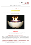
Small Oval Gas Fire Bowl
[with Remote Control Ignition System]
For use with Natural Gas or LPG/Propane (See Data Plate)
Important
It is recommended, even if you have fitted these appliances
before, that you take the time to read through these
instructions and ensure that you follow them step by step.
Serial Number ………………………………
Please quote this serial number when calling our Customer Service team
regarding Warranty issues or to order spare parts. The warranty is valid
for 1 Year from the date of delivery. The Warranty card supplied is to be
completed by the Installer and returned to the address below.
This manual must be handed to the owner of the property once the
fire is commissioned and retained for future reference.
Spirit Fires Ltd. Unit 4 Beaumont Square, Aycliffe Industrial Park, Newton Aycliffe, County Durham, DL5
6XN. Tel: 01325 327221, Fax: 01325 327292, Email: [email protected], Web: www.cvo.co.uk
Contents
Page 3
Technical Data
Page 4
Unpacking the Appliance
Page 5
Remote Control Information
Page 6
General Requirements
Page 7
Installation Instructions
Page 10
Commissioning the Fire
Page 11
Re-setting the Appliance
Page 13
Remote Control Options
Page 14
Lighting the Fire
Page 20
Fault Diagnosis & Troubleshooting
Page 21
Gas Fire User Instructions
Page 2 of 31
Technical Data
Specifications
Pilot Burner Assembly
NG: P4/10 (or P4/10D, Holland Only), LPG: P4/16
Gas Inlet Connection
8mm O.D. Tube
Minimum Flue Diameter
178mm
Minimum Flue Height
3m
Approximate Weight
22kg
Small Oval Gas Fire Unit
Main
Burner
Injector
Size
(1 per
appliance)
Heat
Input
kW
Gross
Setting
Pressure
(HIGH)
Mbar
7.4
9.5
7.4/7.0
9.5/8.8
7.4
9.5
7.0
8.8
6.6
17.4
15.4
17.4/21.7
15.4/19.1
17.4
15.4
21.7
19.1
18.5
Gas
Type
Category
Inlet
Pressure
NG
I2H
20
NG
I2E+
20/25
NG
I2E
20
NG
I2L
25
PROP
I3P
30
460
*95
460
*95
460
*95
460
*95
1.45
PROP
I3P
37
1.45
7.0
19.6
PROP
I3P
50
1.27
7.9
31.9
Country
AT, DK, ES, FI, GB,
IE, IT, PT, SE
FR,BE
DE, LU
NL
NL
BE, ES, FR, GB, IE,
PT
AT, NL, DE
High Flame Picture
PROP
I3P
30
1.60
8.5
29.2
PROP
I3P
37
1.60
9.5
36.0
Minimum Flue Diameter
Minimum Flue Height
NL
BE, ES, FR, GB, IE,
PT
203mm
1m
There are 2 heat input versions of this bowl. See Data Plate for model being fitted.
* Indicates the Large Power and Flame Version
Small Oval (Bowl) Dimensions
Model
Height (mm)
Depth (mm)
Width (mm)
195
330
490
Small Oval Fire Bowl
Unit
Required Fire Opening Dimensions
Model
Max Height
(mm)
Min Depth
(mm)
Max Width
(mm)
Enclosure Size
For Propane at 50mbar
620
570
460
670
620
500
Page 3 of 31
Unpacking the Appliance
Read these instructions fully before proceeding
Carefully examine the carton for damage before unpacking. If it is
obviously damaged, consult the supplier over whether to proceed.
Remove the fire and examine its general condition. If satisfied by the
condition proceed with the installation.
The installation should only be carried out by a Gas Safe Registered
fitter and in accordance with national and local regulations for both
gas & electricity.
The installation must also be in accordance with the relevant parts of local
and national building regulations. For the Republic of Ireland, reference
should be made to IS 813 and ICP3 and any guidance notes from Bord Gais.
Failure to have the fire fitted by a qualified person will invalidate the
Warranty, and CVO Fire will not accept any claims for incorrect
installation.
Page 4 of 31
Remote Control Information
Read through this section before starting the installation
The installation should only be carried out by a Gas Safe Registered fitter
and in accordance with national and local regulations for both gas &
electricity. The installation must also be in accordance with the relevant
parts of local and national building regulations. For the Republic of Ireland,
reference should be made to IS 813 and ICP3 and any guidance notes from
Bord Gais.
Failure to have the fire fitted by a qualified person will invalidate the
Warranty, and CVO Fire will not accept any claims for incorrect
installation.
Power Supply
230v AC-15%+10%, 50/60 Hz
Max power consumption
20VA cos 0.6 (Peak)
Stand-by power consumption
1W
Ambient Temperature
0.80 C
Protection
IP 20
Humidity
Max 95% at 40c
Electrical protection
Not required
Connections
STELVIO/STOCKO
Waiting time for demand
3-5 seconds typically
Ignition Time
20 seconds typically
Ignition Frequency
1Hz
Spark gap
Max 6mm
Ignition Cable length
500mm
A mains connection is required close to the fireplace-a 0.7m cable is
provided for this purpose with a special plug connected to the burner
control box. A 3amp socket may be used, or a fused spur outlet can be
purpose provided. The colour code of the mains is as follows:
Green/Yellow = EARTH : Brown = LIVE : Blue = NEUTRAL
The appliance must be in a position so that the mains supply is
accessible for routine maintenance.
A 3amp fused should be fitted in the plug of fused spur.
WARNING – This Appliance Must be Earthed
Page 5 of 31
General Installation Requirements
This fire is intended for decorative purposes. The installation must be in
accordance with National Regulations and must be carried out by a qualified
installer.
Clearances between the fire and all combustible materials must conform to
National Regulations.
This fire must be installed and used in accordance with these instructions.
Prior to installation, ensure that the local distribution conditions
(identification of the type of gas and pressure and the adjustment of the
appliance) are compatible.
The builders opening or fireplace opening must be constructed of a noncombustible material. When installed, this unit should be located to the rear
of the fire opening. For some countries a non-combustible hearth must be
fitted in front of the fire in accordance with National Regulations (e.g. United
Kingdom).
Any flue damper plate or flue restrictor must be removed or fixed
permanently in the fully open position, or shall only be fitted in accordance
with National Regulations.
The chimney must be swept before the appliance is installed. NOTE: If the
chimney is not swept, there is a possibility that loose debris will fall onto the
appliance which may result in damage and unnecessary service costs.
Before the fire is installed a flue test in accordance with National Regulations
should be carried out. The unit must not be installed unless the chimney /
flue length is at least the length and size indicated in the ‘Technical Data’
section. Under no circumstances should this unit be installed and operated
within any premises without an adequate flue or chimney system.
The gas connections must be in accordance with National Regulations.
An isolation valve, or valves, has to be fitted adjacent to the appliance
which, when closed, allow(s) the complete burner and control assembly to
be disconnected for maintenance or repair in accordance with National
Regulations.
The pilot light and flame sensing device fitted to this fire is also an
atmosphere sensing devise. If for any reason any part of the pilot assembly
is to be replaced ALL the assembly including the pilot burner, thermocouple,
electrode and injector must be exchanged complete for an original
manufacturer’s pilot assembly only. This atmosphere sensing devise is not
adjustable and must not be put out of action. The pilot light shuts off both
the main burner and pilot if evacuation of the combustion products is
interrupted. If the fire shuts itself off, do not use the fire, and have the flue
and fire checked by a suitably qualified person. The correct method for relighting is shown in the ‘Re-set the Appliance’ section.
Page 6 of 31
Installing the Fire Bowl.
The installation should only be carried out by a qualified Gas
Safe Registered fitter and in accordance with National and local
Regulations for both gas and electricity otherwise this will
invalidate your guarantee.
Step-1
Check the packing label on the box to confirm gas type and gas pressure
required for the bowl to be fitted and ensure this complies with the property
supply.
Step-2
• If the bowl is being installed in a customer fabricated enclosure check
that the enclosure size, flue system and flue length comply with the
technical requirements set out ion page 3.
• If the bowl is to be installed in a CVO fabricated enclosure ensure the
flue system and flue length comply with the technical requirements set
out on page 3.
• Decide the location of the bowl within the enclosure.
• Ensure there is an 8mm gas line inlet. If the distance of the gas pipe
exceeds 1.5mtrs it is recommended that after this point the gas pipe
work is increased to 15mm and possibly 22mm to avoid pressure
problems and nuisance shutdowns.
Step-3
• The bowl must be secured within the enclosure to do this the burner
unit must be removed from the bowl. The burner unit is pre screwed in
the bowl, these screws are to be removed using a 2.5mm allen key
(provided). This is to gain access to the burner workings. These screws
are located at each end of the burner as shown in the diagram below.
• WARNING : Do not remove any other screws from the top as
these hold the matting in place this will damage the gas fire
and the fire will need to be returned to the factory for testing.
• When the two screws have been removed from the burner, gently lift
out the unit. This will gain access to the gas inlet valve and the fixing
of the bowl.
• NOTE: Wiring and pipe work is best fitted through the back hole of the
oval bowl.
• NOTE: It is very important that all electrical connections are fitted in
their correct location, as they may become loose while the burner is
handled during installation.
Page 7 of 31
Diagram of Burner Removal
Step-4
• Once removed place he burner unit in a safe location.
• The base of the bowl has holes which can be used to secure the fire
bowl into the enclosure by the use of screws and rawl plugs. See
Diagram below.
• Failure to secure the bowl will result in an unstable installation which
may cause gas leaks.
• By feeding the gas inlet pipe and the mains lead through the hole in
the back of the bowl re-fit the burner unit into the bowl again ensuring
no connections have been disturbed.
Page 8 of 31
Step-5
• Decide the location of the “Hard Wire” Remote switch.
• Remove the switch from the “GREY” hard wire cable and store in a
safe place.
• Route the grey cable to the desired location and refit the wall switch
ensuring the wiring is in the correct order [see wiring diagram] –
failure to wire the switch correctly will result is damage to the remote
system.
• A 240V 3A Fused spur is required to connect the mains supply for the
remote. This must be position in a location so the property owner can
check and replace the fuse should this be required.
• Connect the “BLACK” mains cable to the fused spur. For easy
installation, it may be necessary to join the mains lead with the bowl
unit, and allow a suitable length of wire to the location of the 3 amp
fuse spur.
• WARNING: DO NOT connect the hardwire lead (Grey or white) to the
mains, as this will damage the unit.
Small Oval Remote Burner - Perspective View of Front:
Page 9 of 31
Small Oval Remote Burner – Perspective View of Back:
NOTE: Gas inlet runs through the back hole of the bowl
Commissioning the Fire
TEST THE GAS PRESSURE. Turn the fire on full; attach a manometer
to the inlet test point and ensure there is a pressure of 20mbar (+/1mbar) for natural gas appliances or 37mb for propane appliances.
Now turn on all the other gas appliances in the house and re check
pressure. The pressure must still be in the tolerance of +/- 1mb.
Now turn off all the other gas appliances and turn the fire down to
pilot only, the pressure must still be in the tolerance of +/- 1mbar. If
it is not, TRANSCO, BORD GAIS or the propane supplier must be called
to adjust the governor to the house before the fire can be
commissioned further.
Brief the customer on the operation of the appliance and give them
the instructions. The customer must be told of the need for regular
servicing of the appliance, this will be at least once a year, and be
made aware that no rubbish is to be thrown onto the fire bed. The
customer must also be aware that purpose provided ventilation
should be checked regularly.
Page 10 of 31
The installer must check that all of the combustion products are
entering the flue after 10 minutes by traversing the perimeter of the
fireplace using a smoke (match).
If you have any questions, or the fire is not operating correctly,
please contact the CVO Technical team BEFORE you leave the
installation. As part of our Customer Service procedure you will be
asked for the Fire Serial number [front cover] and Gas Safe
Registration.
If the appliance is not fitted in strict accordance with these
instructions this will invalidate the Warranty, and CVO Fire will not
accept any claims for incorrect installation. CVO Fire cannot be held
responsible for any damage caused due to incorrect installation and
reserve the right to charge for any corrective work.
Re-setting the Appliance
Hand Held Remote Unit
To start your appliance, press both buttons on the hand-held remote
unit, hold them down for a minimum of three seconds until the ignition
process begins which will run for 19-20 seconds before it turns onto the
main burner. After the burner has ignited, it can then be switched to
high or low using the one on the right side of the handset.
Wall Mounted Remote Switch
Unlike the hand held unit, you are only required to press one switch.
Press the left switch for 2 – 3 seconds. The ignition sequence will
continue for 20 seconds before the burner is ignited to high flame
position. The right button is only for turning the fire from high to low
setting and vice versa.
Warning - This Appliance Must be Earthed
Please Note: The remote system is supplied with both the hard-wired
wall mounted switch and infrared system as standard.
Both options allow full control of the fire. Both options can be used in
tandem. Alternatively the infrared can be used without the wall-mounted
switch; vice versa the wall-mounted switch can be used with out the
infrared system.
It is very important when removing one option or the other that it is done
correctly in order for the option left to function correctly on its own.
Page 11 of 31
The wall mounted switch and cable carries low voltage, (20v). The colour
code used in the switch wiring diagrams must not be confused with
normal mains colour coding.
Option 1 – Choosing the Infra-Red System
The following procedure should be carried out:
Trace the cable on the wall-mounted switch back to the main body of the
fire. Access to the small interphase is via the top cover situated under the
burner shell, this is fastened in place with small counter sunk Allen
headed screws. Once this panel has been removed you will have access
to the junction at the end of the white cable, this is insulated with
insulation tape.
The tape will need to be removed in order to gain access to the small
junction terminal, there you will find three wires: green-yellow, brown
and blue.
Note: Using a small electrician’s screwdriver release all three wires from
the terminal block. It is very important to insulate the terminal before
putting the terminal back in the box.
Then replace the front cover and continue with the installation.
Option 2 – Choosing the Hard-Wired Wall Mounted Switch
If you choose to run the fire without the infrared system and just
use the hard-wired wall mounted switch, the following procedure
should be followed:
Trace the infrared eye back to the firebox. Once you have gained access
via the top cover situated under the burner shell, this is fastened in place
with small counter sunk Allen headed screws.
In order to release the small socket you will need a small electricians
screwdriver to prize back the plastic tag on the circuit board that holds
the socket in place.
Page 12 of 31
Remote Control Options
The remote system is supplied with both the hardwired wall switch and
infrared system as standard. Both options can be used as tandem;
alternatively the remote control can be used without the wall-mounted
switch and vice versa. It is very important when removing an option it
is done correctly in order for the option left to function correctly on its
own.
Oxygen Depletion Pilot System
There is a highly sensitive oxygen depletion sensor designed into the pilot
light. If any part is damaged the entire unit must be replaced. Do not
attempt to bend or alter the flame head, thermocouple or aeration hole. Use
only genuine spare parts as similar looking parts from other appliances may
well give different or inferior performance and could lead to a hazard.
Page 13 of 31
Lighting the Fire
Infra-Red Remote Operation
Infrared systems require “Line of sight” between the handset and the
sensor at the appliance, it is a standard safety feature to ensure that
the appliance cannot be remotely lit from another room.
Hardwired Wall Mounted Switch
Press the ON/OFF bottom (left side) for 2-3 seconds (until the spark
ignition sequence begins) and release. The ignition sequence will
continue for a further 10-15 seconds before the burner is ignited to the
“High position.”
To switch off, press the ON/OFF button for 2-3 seconds.
Page 14 of 31
Press the HIGH/LOW button (right side) for 2-3 seconds the
appliance will change to low rate. This operation is repeated to
switch between high and low.
Page 15 of 31
Infra-Red Remote Operation
Infrared (IR) systems require “Line of sight” between the handset and
the appliance. This is a standard feature to ensure the appliance cannot
be lit from another room.
Page 16 of 31
Infra-Red Remote - Replacing the Battery
The Remote Controls - Black Box
Page 17 of 31
Remote Valve
Spark Failure
The gap between the pilot electrode and the pilot should be 3.5 –
4.5mm and normally adjustment is not necessary (the electrode is very
brittle). The spark should jump across the gap between the electrode
and the gas outlet on the pilot head. If the ignitor fails, a lighted taper
can be inserted into the pilot area to check that gas is reaching the
pilot.
Page 18 of 31
Remote Wiring Diagram
8.11 Troubleshooting for Remote version
All CVO Fires are given a full function test at the factory including being run for a number of minutes on
full gas supply to ensure that the unit functions correctly. It is highly unlikely, that if the unit has been
installed correctly as set out in this manual that the fire will not function. Please use the fault diagnosis
tick sheets to resolve any issues which may arise.
Page 19 of 31
Fault Diagnosis
Symptom
Unit does
not respond
Remote
handset
does not
work
Hardwire
manual
switch does
not work
Unit clicks
but no
spark or
weak spark
Check List
Check remote handset is working properly and battery is
charged
Check power supply has not been switched off
Check fuses in spur
Check wiring is correct on fire and hardwire switch
Check battery power
Check remote eye is visible and facing in the correct
position
Check switch is wired properly
Check hardwire switch’s green block is wired correctly
Check spark lead is connected properly
Check spark electrode is in the correct area and the gap
correctly distanced
Check for a good spark
Unit sparks
Check the spark is in the right area
but does not
Check the ventilation is not too strong and the flame is not
light pilot
blowing off the thermocouple
Check isolation tap/shut off valves are free from grease
There is no Check isolation tap/shut off valve are on
gas
Check for blockages
Check gas working pressure is correct:
There is gas Check gas working pressure is correct:
Check for blockages in pipes
but pilot
does not
Check for draughts which can reduce pilot flame
light
Check the pilot gas slot is clear of debris
Check the pilot flame is heating the thermocouple and there
is a draft shield fitted if required
Check the thermocouple nut is properly tightened into the
Pilot lights
valve/interrupter block
but does not
Check that the pilot lights early on ignition clicks
light main
Check ventilation is not too strong and the flame is not
burner
blowing off the thermocouple
Check gas working pressure is correct: NG – 20mBar, LPG
37mBar
Check thermocouple nut is properly secured to the
Burner
interrupter block on the valve and flame failure device is
lights but
operating correctly
turns off
Page
20 strong
of 31
Check ventilation is not
too
and the flame is not
after a few
blowing off the thermocouple
minutes
Check gas working pressure is correct:
Tick
INSTALLATION MANUAL & USER HANDBOOK
Small Oval Gas Fire Bowl
[with Remote Control Ignition System]
For use with Natural Gas or LPG/Propane (See Data Plate)
Important
It is recommended, even if you have fitted these appliances
before, that you take the time to read through these
instructions and ensure that you follow them step by step.
Serial Number ………………………………
Please quote this serial number when calling our Customer Service team
regarding Warranty issues or to order spare parts. The warranty is valid
for 1 Year from the date of delivery. The Warranty card supplied is to be
completed by the Installer and returned to the address below.
This manual must be handed to the owner of the property once the
fire is commissioned and retained for future reference.
Page 21 of 31
Contents
Page 23
General Instructions
Page 24
Exchangeable Components List
Page 25
Servicing Instructions
Page 26
Cleaning Instructions
Page 29
Fire Guards & Other Information
Page 30
Warranty Information
Page 22 of 31
GENERAL INSRUCTIONS
This fire is intended for decorative purposes. Any purpose-provided
ventilation should be checked regularly to ensure that it is free from
obstruction. The fire should be serviced regularly by a qualified person.
The chimney should be swept before the appliance is installed, and
should be swept and inspected regularly to ensure that all of the
products of combustion are entering the flue and there is no excessive
build up of soot.
Do not throw rubbish et cetera upon the surface area or otherwise
disturb the fuel bed. Debris from any source, or soot formed, should be
removed from time to time, see ‘Cleaning instructions’.
The pilot light and flame sensing device fitted to this fire is also an
atmosphere sensing device, which shuts off both the main burner and
pilot if evacuation of the combustion products is interrupted. If the fire
shuts itself off, do not use the fire, and have the flue and fire checked
by a suitably qualified person.
Once the flue and fire units have been checked and remedial action
taken, the fire is ignited in the manner depicted in section ‘Lighting the
fire’.
Due to the newness of materials, the fire may give off a slight smell for
a period of time after commissioning. This is quite normal and any
odours should disperse within a few hours of operation.
For some countries a purpose provided air supply must be fitted in
accordance with National Regulations (e.g. Austria – minimum
100 cm2).
This fire should be checked regularly to ensure that it is free from
obstruction. A qualified person should service the fire regularly.
NOTE: MANUAL CONTROL VERSION – The bowl must be secure to
the base which it is mounted. If the bowl moves or “rocks” from side
to side when operating the control knob the bowl will become
damaged. In the event of this happening the installer should be
recalled to secure the bowl.
Page 23 of 31
Exchangeable Components List
Part
Code
Code
Number
Item Description
Engineer
User
Exchange Exchange
Parts?
Parts?
GC002
Gas Valve (Remote)
GC002
Yes
No
AC009
Pilot Unit (NG Remote)
P4-05
Yes
No
P4-16
Yes
No
Yes
No
Yes
No
Yes
No
Yes
No
-
Yes
No
CVO3/C
No
No
CVO3/MS
No
No
CVO3/SW
Yes
No
CVO3/SB
Yes
No
CVO/S
Yes
No
-
Yes
No
AC007
AC021
AC097
Pilot Unit (LPG Remote
with M9 Nut)
Small Flame Picture
(NG/Remote)
Small Flame Picture
(LPG 30/37 Remote)
AC021
Large Flame Picture (NG
Remote)
AC097
Large Flame Picture
(LPG 30/37 Remote)
AC026
Isolation Tap
FC002
Ceramic Matting Panel
AC029
Mesh Support Panel
Small Outer Bowl Shell
BC008 White Concrete
BC027
Black Concrete
BC023
Bronze
BC064
Aluminium
Injector
CVO/460
Injector
CVO/1.45
Injector
CVO/460
Drilled
Injector
CVO/1.50
Page 24 of 31
Servicing Instructions
General
The following servicing procedure should be carried out regularly and
only by a qualified person.
Note: foreign bodies which can gather on the surface of the burner
unit it is inevitable that servicing can be a dusty operation. Suitable
precautions should be taken.
Important: The pilot and flame sensing device fitted to this fire is also
an atmosphere sensing device. If for any reason any part of the pilot
assembly is to be replaced, the entire assembly including the pilot
burner, thermocouple electrode and injector must also be exchanged.
This atmosphere sensing device is not adjustable and must not be
disabled.
Servicing procedure
Step 1:
Turn off the fire and allow it to cool.
Step 2:
Turn off the gas supply at the isolation tap.
Step 3:
Disconnect the gas pipe from the valve. Lift the burner
tray clear of the fire bowl.
Step 4:
Remove the venturi cover screw and venturi cover (natural
gas only), then remove and clean the injector. Do not use
a needle or wire. It may be necessary to remove the outer
fire casing to gain access to the injector.
Step 5:
Using a soft brush or vacuum cleaner, remove any debris
from the top surface of the fire unit.
Step 6:
Re-assemble in the reverse order, and re-connect the gas
supply.
Step 7:
Check for gas soundness.
Step 8:
Check that any purpose-provided ventilation is free from
obstruction.
Step 9:
Re-commission the fire as described in ‘Commissioning the
fire’.
Page 25 of 31
Cleaning Instructions
Cleaning the Gas Fire Unit
Note: due to the surface area and flatness of the ceramic burner
matting, it is inevitable that dust, debris from the chimney and
combustion by-products will accumulate, consequently the surface area
of the fire unit should be cleaned at regular intervals.
The most effective method of dust/debris removal is achieved with the
aid of a vacuum unit, however, great care must be taken to ensure that
there is no contact between the vacuum unit and the surface area of the
fire unit, as damage to the matting material will result in the complete
replacement of the matting panel.
Turn off the fire unit and allow it to cool.
Once cool, using a vacuum cleaner with a soft brush head gently
remove any debris/dust from the surface of the fire unit.
After ensuring that no damage has been done to the surface of the fire,
the unit is ready to re-ignite.
Cleaning Stone Components
Once installed, the unit should be dusted periodically to remove
naturally collecting dust particles from its surfaces - this can be done
using a duster or vacuum cleaner.
Note: where a vacuum unit is used it should have a soft brush head to
prevent the risk of damage or marking to the unit.
Removing Spillages
Where a liquid has been spilled onto the surface of the unit, it should be
removed quickly to prevent staining or serious damage. A solution of
warm water and organic cleaner will give best results. Apply the mixture
with a dabbing motion, using a sponge. The sponge is squeezed dry and
used to dab up the cleaning mixture from the surface until all evidence
of the spillage has been removed. The surface can then be allowed to
dry naturally.
Removing Scuff Marks
Removal of scuff marks should be carried out in the same manner as
above if attempting to remove a spillage. However on Limestone it may
be necessary to use a scotch brite pad in a slight scrubbing action to
remove stubborn marks. If the scuff mark persists it may be necessary
to use a stronger cleaner. Please contact CVO Fire for details.
Page 26 of 31
Removing Powders, Soot, Ash or Grit
These should be removed without the use of liquids of any kind. Best
results are achieved by using a vacuum cleaner; to lift the particles
from the surface of the surround, or by blowing or fanning the particles
away with a piece of card.
If, after removing the powder there is still evidence of a staining, this
can be removed by using an organic cleaner mix as stated previously.
Removing Wax
However, in the event of molten wax falling onto the surface, the
following method of removal is suggested. Do not attempt to remove
any spilled wax whilst still molten, attempting to rub away the spillage
will simply spread it across a greater surface area.
Once cooled any heavy globules of wax can be picked away from the
surface. Next place a piece of heavy blotting paper over the affected
area, and run a hot iron over it, the wax which is melted by the iron will
be drawn away from the surface of the surround by the blotting paper.
It may be necessary to repeat this process several times until all the
wax has been successfully removed.
If blotting paper cannot be obtained a heavy-duty kitchen towel or
similar absorbent material will suffice.
Cleaning Metal Components
Bronze metalwork can be kept clean by simply dusting or wiping with a
damp cloth. Where bronze metalwork has become tarnished, a highly
polished finish can be achieved using a cloth and a propriety brass
cleaning fluid - simply follow the instructions given on the container.
(Brass cleaner fluid is available from hardware stores to add an extra
shine.)
Fine (0000 grade) wire wool can be used to remove slight scratches
from brushed steel should they occur. Please note that you must always
rub the metal in the direction of the grain.
Do not rub in a circular motion or across the grain.
In the interest of personal safety, please do not attempt to clean the
metalwork when the fire is ignited or the metalwork is still hot.
Bronze Service and Aftercare Requirements
Page 27 of 31
When completing the annual service of the Bronze Cube Unit,
refer to the enclosed technical installation and operational
manual & the optional remote control instruction document.
The gas unit should be installed to the manufacturer’s instructions by a
Gas Safe registered gas installer, every 12 months the gas fire unit
should undergo a regular service, this work should be carried out by a
competent person who is Gas Safe registered and familiar with the CVO
Fire range of goods.
When carrying out the annual service, the competent person
should examine and verify the following;
1.
2.
3.
4.
5.
6.
The correct safe operation of the ODS (oxygen depletion system)
That the fire unit correctly cross-lights
A pressure drop test to verify that there are no gas leaks
That the electronic ignition system operates correctly
That the burner surface is free from damage and debris
That the owner has a copy of the installation and operation manual
Burner Surface Cleaning Procedures
Note: the gas fire must be switched off when cleaning the
burner surface.
The burner surface is made from carbon coated glass material, the gas
passes through the matting and is ignited above the burner surface, any
debris which may fall onto the surface from the chimney or flue system
can potentially reduce the efficiency of the fire unit, consequently the
surface of the burner should be kept clean.
Great care must be taken in removing large debris from the surface of
the glass matting. Excess cleaning will damage the surface. Holes in the
surface mean the bowl cannot be used until the matting is replaced.
This can only take place at the factory. NOTE: the surface is delicate to
handle but does not damage through heat.
Every unit has been designed, manufactured and type tested to ensure
that it conforms to the current National and European DFE (Decorative
Fuel Effect Gas Fire) Legislation, Low Voltage Directive (LVD) and the
Electro Magnetic Compatibility Directive (EMC), (which is required for
remote control units only).
If you have any queries or doubts regarding these instructions or
require additional support or advice on our products, please contact our
CVO Technical Department on 01325 327221.
Page 28 of 31
WARNING: Fire Guards
This appliance is not fitted with an integral guard. In normal
use consideration may be given to the use of a fireguard
conforming to BS6539 or BS6778, so that the approach to the
appliance is limited such that access to the flame is minimised
It is recommended that a fireguard conforming to the requirements of
BS6539 or BS6778 be fitted if the fire is used in the presence of young
children, the elderly or the infirm.
The installer is to advise the user not to stand too close to the
appliance for prolonged periods of time and warn that loose clothing is
particularly at risk of burning due to the presence of an unguarded
flame.
In addition, the installer is to advise the user against placing
combustible material directly in front of the appliance. Floor coverings,
such as carpets, are considered to be acceptable.
Hearths
For some countries a non-combustible hearth must be fitted in front of
the fire in accordance with National Regulations (e.g. United
Kingdom).
Metal Cast Bowls
Bowls which are manufactured from Cast Metal are sand cast at a UK
Foundry and then Hand Polished for over 15 Hours at the CVO Fire
Factory. Pitting and Air Holes are a normal occurrence and are a part of
the unique quality of such a hand made piece. All Bowls are inspected
and given a full quality control check at the factory. If the Bowl supplied
includes Pitting and Air Holes this will have passed the in-house
inspection and cannot be used to form a Warranty claim. We hope that
you will see that the overall beauty and uniqueness of your CVO Fire
outweighs what is a very minor feature.
Page 29 of 31
WARRANTY
This appliance is supplied with a manufacturer’s warranty
which is valid from 12 months from date of delivery.
The Warranty covers defective components only and does not
cover damage caused by incorrect installation or normal wear
and tear caused by usage.
When making a Warranty claim you will be required to supply
the serial number of the appliance [as shown on the front of
this booklet] and full details of the GAS SAFE registered
engineer who installed and commissioned the appliance. We
make ask for proof o install and a copy of the receipt.
The warranty does not include damage to the matting surface
which is highly durable and will last the life of the product
under normal usage.
Damage to the outer surface to the bowl caused by handling or
cleaning is not covered by the warranty.
Page 30 of 31
ONLY USE GENUINE REPLACEMENT PARTS
To order Spare Parts please contact Customer Services on 01325 327221.
Opening hours are 9.15am to 3.15pm Monday to Friday.
For further Technical information please call our CVO
Technical Department on 01325 327221.
Spirit Fires Ltd.
Unit 4 Beaumont Square,
Aycliffe Industrial Park,
Newton Aycliffe,
County Durham,
DL5 6XN.
Tel: 01325 327221,
Fax: 01325 327292,
Email: [email protected],
Web: www.cvo.co.uk
The following information supplied in this manual is
correct at the time of publish; Updated on the 7-10-2009.
There may be changes made in future as we improve our
products. If there are any queries please write or call our
Technical Department.
Page 31 of 31