1
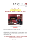
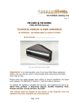
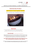
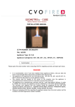
Rev-18
PIN NUMBER: 0558BO5341
TECHNICAL MANUAL & USER HANDBOOK
FIRE LINE FLUELESS
[Manual Ignition Version]
This Manual covers both “Classico” (with Polished Interior) &
“Moderno” (with Black Interior) Models with either a Standard
(970mm) or Wide-Screen (1080mm) Fascia, for use with Natural
Gas or LPG.
Important :
It is recommended, even if you have fitted
these appliances before, that you take the time to read through
these instructions and follow them step by step.
Appliance Serial Number ………………………………
Please quote this serial number when calling our customer service team
regarding warranty issues or to order spare parts. The Warranty is valid
for 1 Year from date of delivery. The Warranty card supplied is to be
completed by the installer and returned to the address below.
This manual must be handed to the owner of the property once the
fire is commissioned and retained for future reference.
Spirit Fires Ltd. 4 Beaumont Square, Aycliffe Industrial Park, Newton Aycliffe, County Durham, DL5
6XN. Tel: 01325 327221, Fax: 01325 327292, Email: [email protected], Web: www.cvo.co.uk
WARNING
This appliance is designed to be “Wall Mounted”.
The gas fire is approved to be recessed into the
wall ONLY when used with the CVO manufactured
recess system. Under no circumstances should this
appliance be installed recessed into the wall using
another style of recess system. Failure to observe
this warning could render the appliance highly
dangerous; it will no longer comply with the CE
approval or the Manufacturers Warranty. If in
doubt call 01325-327221 before starting to install
the appliance.
Contents
Page
Page
Page
Page
Page
Page
Page
Page
Page
Page
Page
Page
Page
Page
Page
Page
Page
Page
Page
Page
3
4
5
7
8
12
13
13
13
14
15
15
17
18
20
21
21
22
25
27
Parts List / Construction Drawing
Introduction
Appliance Technical Data
Unpacking the Appliance
General Installation Requirements
Side View of Fire
Warning For Fire Guards and Hearths
Clearance to Combustible Materials
Preparing the Appliance
Before Connecting the Fire to Gas Line
Fitting Instructions
Commissioning the Fire
Installation Completion
Fault Diagnosis
Fitting Replacement Components
Warning For Fire Guards and Hearths
Flueless Fireline Dimensions –Standard and Wide
Servicing Instructions
Replacement Components List
User Handbook
Page 2 of 34
Parts List / Construction Drawing
Note that the “Moderno” (Black Interior) Version of this fire does not include Liner CC249.
Page 3 of 34
Introduction
This appliance is 100% efficient [90% SAP Rating]. The burner system is
very clean burning and does not require glass or catalytic converters. The
fire is fitted with an Oxygen Depletion Sensor which will sense any
significant oxygen depletion in the room and shut the fire down safely.
The Fire Line (Flueless) – CE PIN: 0063B05341
These instructions are intended for use in GB and IE. Fire is approved for
other European destinations and gas categories (as shown below). Check
Packing box label and Data Plate for appliance gas type and categories
before starting to install this fire. Check the required room ventilation and
minimum room size before installing the fire.
This appliance is for use with the following gas categories, gases and supply
pressures:
•
Natural Gas:
o I2H - G20 at 20mbar
o I2L - G25 at 25mbar
o I2E - G20 at 20mbar
o I2e+ - G20 at 20mbar & G25 at 25mbar
•
LPG/Propane
o I3P - G31 at 37mbar
o I3B/P - G30/G31 at 30mbar
o I3+ - G30/G31 at 28-30/37mbar
Important
It is recommended, even if you have fitted these appliances before,
that you take the time to read through these instructions and follow
them step by step.
Page 4 of 34
Appliance Technical Data
Refer to the appliance data plate (affixed behind the fascia) within the
burner carriage. ENSURE THAT THE LOCAL CONDITIONS OF USE
CORRESPOND TO THE DATA ON THE BADGE. * See Data Plate for Input
Rating.
Page 5 of 34
Warning: Minimum Requirements
Before installing this appliance the installer must check that the
property in which the fire is to be installed complies with the
requirements of CE approval:
•
•
•
•
•
The appliance must not be installed in a room smaller than that
specified.
The room in which the appliance is to be installed must have a “free
air” wall vent of the specified size. This vent must be a minimum of 1
metre away from the appliance.
The room in which the appliance is to be installed must have a window
which can be opened.
The Inlet Gas pressure must be maintained at the specified level and
must be within +/- 1mbar of specification with all gas appliances in
the house switched on and also with just the Fire Line operating. If
outside of this tolerance the fault is most likely to be in the installation
pipe work or service governor at the meter. If the problem is the
meter governor, this is the property of the gas service provider (such
as Transco or Bord Gais) and they should be called to rectify this.
For gas categories 2H, 2E and 2E+ only, the reduced heat output
version is available at high low input of 2.7/2.0kW at burner pressures
of 12.2/6.9mbar.
Noisy Pilot / Fire Shut Down
This appliance is fitted with a safety device. This will operate if the
requirements of the installation are not met. If the fire is run for a period of
time and starts to become noisy or suddenly shuts down this indicates a
possible problem. The most common fault is incorrect ventilation. The
ventilation is quoted as “free air” – it is not the size of the actual vent. Each
vent has a specified “free area”. Contact the manufacturer of the vent and
ask for this figure and check it complies with the minimum specified for the
appliance. This is a secondary heat source appliance and is supposed to be
used for short periods of time however it can also incorrect installation. If it
shuts down or is noisy - Do not use the appliance – Ask your installer to
return and confirm the following conditions are met before using the
appliance:
• Minimum Room Size
• Is the pilot shield fitted [see page 21]
• “Free Air” Wall Vent of specified size is installed in room.
• “Free Air” Wall Vent is not blocked.
• “Free Air” Wall Vent is over 1 metre away from the appliance.
• Gas pressure is within the specified limits +/- 1mBar.
• Room appliance is installed in has a window which can be opened.
Failure to comply with the minimum requirements of the specification will
render the appliance dangerous.
Page 6 of 34
Unpacking the Appliance
Read these instructions fully before proceeding
Carefully examine the carton for damage before unpacking. If it is obviously
damaged, consult the supplier over whether to proceed.
Check Contents before proceeding:
• Gas Fire (Box #1)
o Gas Fire.
o Wall Bracket.
o Install Booklet.
• Gas Fire Surround (Box #2)
o Fire Fascia
Make sure the carton is stood upright and open the top. Remove the
cardboard, and place to one side; this can be used as a floor protector when
installing the fire. Remove the fire and examine its general condition, paying
particular attention to the fascia, and the stainless steel inglenook. If
satisfied by the general condition, place the decorative components to one
side and proceed with the installation. If in any doubt, seek advice from the
supplier. Read the instructions fully before proceeding.
Page 7 of 34
General Installation Requirements
The installation should only be carried out by a GAS SAFE
Registered fitter and in accordance with national and local
regulations for both gas & electricity.
The appliance is intended for decorative purposes only.
Foreign objects should not be placed on to the appliance or otherwise disturb
the fuel bed. Debris from any source, or soot formed, should be removed
from the appliance, see ‘Appliance Cleaning Instructions’.
The appliance may emit a slight smell for a period of time after
commissioning. This is quite normal and any odours will disperse within a
few hours of operation.
The pilot light and flame sensing device installed to the appliance are also
atmospheric sensing devices. The device is not adjustable and must not be
disabled. If evacuation of combustible products is interrupted the device
shuts down both the main burner and pilot light. In the event of a single
shut down, do not attempt to re-light the pilot within three minutes, once
three minutes have passed the appliance can be re-started in accordance
with ‘Appliance Start Up / Shut Down Instructions’. In the event of repeated
shut downs, do not use the appliance and have the flue and appliance
checked by a CORGI Engineer. If any part of the pilot assembly needs to be
replaced, including the pilot burner, thermocouple, electrode and injector the
complete assembly must be replaced with an original manufacturer's pilot
assembly by a CORGI Engineer.
Warning – Do not adjust the system.
Warning – Do not disable the flame sensing device.
Warning – Use only OEM parts.
The installation should only be carried out by a GAS SAFE Engineer and in
accordance with national and local regulations for gas. The installation must
also be in accordance with relevant parts of local and national building
regulations. For the Republic of Ireland, reference should be made to IS813
and ICP3 and any guidance notes from Bord Gais.
Read the instructions carefully before proceeding. Failure to do so could
result in an unsafe installation and may invalidate the warranty.
Failure to have the fire fitted by a qualified person will invalidate the
Warranty, and CVO Fire will not accept any claims for incorrect
installation.
Page 8 of 34
Input Rating
Power Version *
Minimum Room
Size Requirements
(m3)
2.7kW Input Rating
3.5Kw Input Rating
27m3
40m3
Minimum “Free
Air” Wall Vent
Requirements
(cm2)
100 cm2
125 cm2
* See Data Plate within fire for Input Rating.
VENTILATION REQUIREMENTS
•
•
•
•
•
•
•
•
NOTE: The “FREE AIR” quoted above is the area of air which can pass
through the air vent. It is not the size of the grille on the wall. If in
doubt please contact the vent manufacturer and get the specification
for the vent.
3.5Kw Version - The area the fire is to be installed in must have a wall
vent of at least 125cm² of ventilation (FREE AIR) and an open-able
window.
2.7Kw Version - The area the fire is to be installed in must have a wall
vent of at least 100cm² of ventilation (FREE AIR) and an open-able
window.
The wall vent must be positioned at least 1 metre away from the
appliance.
Republic of Ireland – Two free air wall vents of not less that 60 cm²
each, one not less that 1.6m above the other, must be installed in the
room.
When providing ventilation openings consideration must be given to
the avoidance of locations where discomfort from draughts may cause
the user to block the openings. Similarly the possibility of curtains or
furniture blocking ventilation openings must be considered.
Floor vents, window vents or chimneys are not suitable means
of ventilation. On no account must inlet or outlet grilles be
obstructed. Working services include the air outlet grille.
NOTE: In some installations, if the fire shuts down, additional
ventilation may be required. This can be due to how air circulates
within the room. If this is the case it is advised to add a second vent
positioned away from the first vent at a higher level.
Page 9 of 34
ROOM SIZE REQUIREMENTS
•
•
•
•
3.5Kw Version - The Fire Line must not be fitted in an internal space of
less than 40m³ in volume.
2.7Kw Version - The Fire Line must not be fitted in an internal space of
less than 27m³ in volume.
Adjoining spaces, not separated by a door may be included.
To convert cubic feet (ft³) to cubic metre (m³) divide the room volume
in cubic feet by 35.3.
OTHER REQUIREMENTS
The fire must not be fitted in basements which are not open on at least
one side (an open-able window), bathrooms or in corridors, stairways,
landings or hallways of multi occupancy dwellings, garages or rooms
containing petroleum products.
Although the installation of our Flueless fires in bedrooms is permitted,
CVO Fire does not recommend it - if in doubt please refer to BS5871 2007
for details or contact CVO Fire for further advice.
Soft furnishings, decorations and wall coverings etc. must not be placed
within 1.5 metres of the appliance and its outlets. See Image
Be aware of curtains etc. that could be blown towards the appliance.
Page 10 of 34
SECONDARY HEATING: The fire is intended as a secondary heat source and should
not be used as a primary heat source. Check that a primary heat source (such as
radiators) is present in the room before installing the appliance. The fire should not be
operated if the room temperature is below 15 deg C. If the fire is used in a room without
the primary heat source operating to raise the initial room temperature above 15 deg C
there may be a build up of condensation and it is likely the stone fascia will crack due to
heat shock. When the appliance is used properly there is no risk of the fascia stone cracking
and this damage is not covered by the warranty. Houses with warm air heating systems,
solid walls, or no damp proof course may be unsuitable for flueless appliances. This
appliance does not contain Asbestos.
ROOM AIR QUALITY: The fire must not be used in rooms where the atmosphere is likely
to contain water or chemical vapours that may adversely affect the appliance or its finish
e.g. a kitchen
DECORATING: Do not use the fire while painting or decorating even if it is in an adjoining
room. When decorating the residue can linger for some time and this will lead to unpleasant
smells from the appliance. It may be some weeks before this odour clears and it is advised
not to use the appliance during this period. Always completely cover the appliance while
decorating.
WALL MOUNTED: The appliance has been designed to be installed onto a wall. It must be
placed on a non-combustible surface of minimum of 12mm thickness. The surface on which
the appliance is to be mounted must be flat, level and square to the back panel. Care should
be taken with all wall coverings as it may discolour them in time.
GAS SUPPLY
Before working on any pipe work, plug the ends to prevent the entry of
debris. Decide upon the route for the gas and lay pipe work as required.
Where pipes pass through the walls they must be sleeved. Before
connecting any pipes to the appliance, fully purge pipes of debris or grease
etc. Inlet is via an 8mm gas tap (isolation valve) which is supplied fitted to
the appliance. Connect gas supply to the supplied pressure test point and
then to the 8mm isolation valve as shown below. The pressure test point
MUST BE as close to the isolation valve as possible to ensure
accurate inlet pressure testing when the fire is commissioned.
Page 11 of 34
SIDE VIEW of the Flueless Fire Line (below)
On no account must inlet or outlet grilles be obstructed.
Only the fascia supplied with the appliance must be used. Any other type
could affect combustion or overheat the gas controls. Any other types of
Fascia must be passed by CVO.
If fitting over an existing fireplace, the flue and cavity must be blocked off
completely to prevent suction on the back of the appliance. The top of the
flue should also be capped off to prevent the entry of moisture etc. Consult
building control if in any doubt.
Any under grate draught devices must be sealed off. A hearth will be
required in accordance with both CORGI and local regulations on a noncombustible surface if the fire is to be mounted on the wall less than 300mm
from the base of the burner to the floor.
The client/installer can construct/supply their own hearth or CVO can supply
it as an extra item.
Unless a dress guard is fitted, this appliance shall be installed with a hearth
that projects at least 300mm in front of the naked flame/incandescent fuel
bed, and extends at least 150mm at either side, and around its periphery is
a height of at least 50mm above finished floor level.
Page 12 of 34
Warning for Fire Guards and Hearths
The appliance is not installed with an integral guard. In normal use
consideration may be given to the use of a fireguard conforming to BS6539
or BS6778, so that the approach to the appliance is limited such that access
to the flame is minimised. It is recommended that a fireguard conforming to
the requirements of BS6539 or BS6778 be installed if the appliance is used
in the presence of young children, the elderly or the infirm. For some
countries a non-combustible hearth must be installed in front of the
appliance in accordance with national regulations (e.g. United Kingdom). In
addition, the installer is to advise the user against placing combustible
material directly in front of the appliance.
Clearance to Combustible Materials and Shelves
A non-combustible shelf may be fitted to within 1500mm of the top edge of
the outlet of the fire. Note that shelves will get hot and delicate ornaments;
e.g. wax candles etc. should be kept away from hot surfaces.
As with all flueless fires the possibility of convection staining on surfaces in
the vicinity above the fire outlet shall be considered and the user advised.
Particular attention should be taken to ensure soft furnishings such as
scatter cushions, rugs and curtains are kept at least 1.5 metres from the
appliance. Material of any description should not be thrown on to the fuel
bed.
Preparing the Appliance for Installation
Unpack the unit. Ensure the appliance is correctly marked for the gas it is to
be used with. Take the fascia panel and stand this against a flat surface – Do
not lay the fascia flat.
DO NOT ATTEMPT TO USE THE APPLIANCE IF ANY PART OF THE
APPLIANCE IS FOUND TO BE DAMAGED.
Decide upon a route for the gas supply and if this is to be a concealed supply
it needs to be located to the bottom right of the fire. Lay in the supply as
required. Where pipes pass through a wall, cavity or un-vented void there
should be no joins in this area and the pipes should be fully sleeved. Before
pushing gas pipes through walls seal the pipe ends to prevent debris
entering the pipes.
The instructions for installation and maintenance and the user instructions
shall be handed to the user. The installer shall instruct the user in the safe
use and regular maintenance of the appliance and advise that the ventilation
opening shall not be blocked or restricted in any way.
Page 13 of 34
Before Connecting the Fire
Check ROOM SIZE REQUIREMENTS.
Check VENTILATION REQUIREMENTS.
Check GAS PRESSURE REQUIREMENTS.
Fully purge pipes of air and any debris and connect the gas supply to the
8mm supply on the fire. Leak test the supply using an approved method.
Note: An isolating valve must be situated near the appliance for servicing.
In the even of gas leakage from the appliance the gas supply must be
turned off at the nearest isolating valve.
Before lighting, if the pipes have not been purged of debris do so
now before lighting the fire. Failure to do so will result in blockages
within the pilot.
All CVO gas fires are bench run and thoroughly tested. CVO is in the unique
position of knowing that every fire that leaves the factory in perfect working
order with accurate test records kept for every fire. This ensures every fire
complies with the CE approval.
Connect the 8mm gas inlet to a gas inlet test elbow. This should be
positioned as shown in the images. The elbow should be connected to the
isolation valve as shown in the images.
Gas Inlet Supply – This is via an 8mm gas tap (isolation valve) which is
supplied fitted to the appliance. A Gas Inlet Elbow is required to check inlet
pressure. This is supplied with the fire and must be position as close to the
isolation valve as possible.
It is recommended that if the gas pipe work is in excess of 1.5m the size of
the pipe work should be increased in diameter after this point to ensure a
stable gas supply.
IMPORTANT NOTE: LPG/Propane:
With Outside Tank: The tank must be fitted with a regulator and
suitable pipe work used to ensure the gas pressure (as stated on the data
plate) is maintained at all times. The pressure must be tested “at the
appliance” – see commissioning.
With Bottles: The minimum requirement is 2 x 47Kg bottles with a
changeover valve. Any other connections using bottles will result in
shutdown problems and damage to the fire. The bottles must be fitted with a
regulator and suitable pipe work used to ensure the gas pressure (as stated
on the data plate) is maintained at all times. The pressure must be tested
“at the appliance” – see commissioning.
Page 14 of 34
Fitting Instructions
1. Refer to the section “unpacking the appliance” on page 7.
2. Positioning Wall Bracket.
a. The wall must be flat and level otherwise the burner flame will
be affected.
b. The Wall on which the fire is to be installed must be secure and
able to withstand the weight of the Fire and Fascia.
c. Decide preferred height of fire. (NOTE – There must be at least
300mm clearance between the floor to the fire opening and
1000mm from the top of the gather to the ceiling.
d. To get the desired height measure from the floor to the top of
the gather. Place the top of the wall bracket central and 40mm
lower than the gathers height, and mark out the holes.
e. Drill and plug holes and attach the fixing bracket to the wall
using 3 screws.
3. Place the gas burner unit enclosure onto the wall bracket. Mark out the
position of the lower securing points which are located within the
burner workings [see A above]. Remove the burner and drill and plug
holes then refit the burner onto the wall bracket and secure using the
two screws provided. WARNING: This must be done as it ensures the
fire cannot be lifted from the wall and the burner cannot warp while
operating.
4. A qualified GAS SAFE registered gas fitter must connect the gas to the
fire using the pressure test point provided. [See “Before Connecting
the Fire” Section – Page 14]
5. Once the fire is connected to the gas, fit the fascia in place by locating
the lugs on the back of the fascia into the slots on the burner housing.
As the fascia is heavy, it is advisable that another person helps.
6. Once fitted the fascia must be locked in place, this is done by locating
two cross-headed screws through both the fascias hanging bracket and
the enclosure situated on each side of the unit. [See Page 28]
7. A qualified GAS SAFE registered gas fitter must commission the fire.
[See “Commissioning the Fire” Section – Page 16]
Page 15 of 34
Commissioning the Fire
Refer to ‘Lighting the Fire’ Section for information on the start and shutdown
procedure. WARNING: UNDER NO CIRCUMSTANCES ADJUST THE
FLOW RATES FOR THIS APPLIANCE. The inlet flow rates for the fire are
factory set and are sealed and do not need further adjustment. This ensures
that the appliance complies fully with CE approval.
Test the Gas Pressure.
Ensure the fire has been installed using the test point provided and
in line with the image on PAGE 11.
1. Attach a manometer to an inlet test point next to the isolation valve.
2. Light the Fire and set on the “maximum” heat setting.
3. Check that the inlet pressure is within the allowed tolerance of (+ or 1mb). For example in the UK – Natural Gas (20mBar) should be within
the range of 19 to 21. Propane (37mBar) will be 36 to 38.
4. Now turn on all the other gas appliances in the house and check that
the pressure still remains within the tolerance of +/- 1mb.
5. Now turn off all the other gas appliances and turn the fire down to pilot
only and check that the still remains in the tolerance of +/- 1mb.
IF FAILED : If the appliance fails the above test it must not be used until
either the gas pipe work to the appliance has been improved or the governor
to the house has been adjusted by TRANSCO, BORD GAIS or the propane
supplier. Running this type of appliance with incorrect gas pressure can
result in harmful emissions being released into the room and will render the
appliance dangerous.
IF PASSED : Disconnect the pressure gauge then replace the pressure test
point sealing screw and test for gas soundness. Replace the cover and the
control knob [if removed].
Page 16 of 34
Installation Completion & Final Check List
Brief the customer on the operation of the appliance and give them the
instruction booklet. The customer must be told of the need for regular
servicing of the appliance (every 12 months), this will be at least once a
year, and they must be made aware that no rubbish is to be thrown onto the
fire bed. The customer must also be aware that purpose provided
wall vent “free air” ventilation should be checked regularly and must
“never” be intentionally blocked.
The Fire is supplied with a
Warranty Card this should be completed by the installing Engineer
and handed to the customer for return to the factory.
•
•
•
•
•
•
•
Is the Gas Pressure Correct? (within 1mb of rating)
Is the Air Vent fitted and providing the specified amount of
“free air” – if in doubt contact the vent manufacturer for vent
“free area” sizing.
Does the room comply to the minimum size or greater?
Does the Room have a window that can be opened?
Has the customer being shown how to operate the appliance?
Has the customer been told of the reason for the air vent and
why it must never be blocked?
Has the warranty card been completed and given to the
customer?
If you have any questions, or the fire is not operating correctly,
please use the fault diagnosis section or call the CVO Technical team
on 01325 327221 BEFORE you leave the installation. As part of our
Customer Service procedure you will be asked for the Fire Serial
number [on the front cover of the booklet] and Gas Safe
Registration.
If the appliance is not fitted in strict accordance with these
instructions, CVO cannot be held responsible for any damage caused
and reserve the right to charge for any corrective work.
Page 17 of 34
Fault Diagnosis
All CVO Fires are given a full function test at the factory including
being run for a number of minutes to ensure there are no faults. It is
highly unlikely that if the unit has been installed correctly as set out
in the manual that the fire will not function. The cause is normally
due to an installation fault.
Symptom
Check List
Check for a good spark
Unit sparks but
does not light
pilot
Check the spark is in the right area
Check the ventilation is not too strong
Check there is gas running through
Check isolation tap/shut off valves are free from grease
There is no gas
Check isolation tap/shut off valves are on
Check for blockages
Check inlet gas pressure is correct
There is gas
but pilot does
not light
Check for blockages in pipe work
Is there another gas appliance in the house which is causing a
pressure drop?
Check for strong draughts
Check the pilot gas slot is clear
Check the pilot flame is heating the thermocouple
Pilot lights but
does not light
main burner
Check the thermocouple nut is properly tightened to the valve
Is there another gas appliance in the house which is causing a
drop in gas pressure?
Check Room Size and Free Air Vent Comply to CE approval as
shown in Technical Data
Burner lights
but turns off
after a few
minutes
Check thermocouple nut is properly secured to the valve
Check that drafts are causing the pilot flame to blow off the
thermocouple
Is the gas pressure correct? Is there another gas appliance in
the house which is causing the gas pressure to drop?
Check “Free Air” Wall Vent is not blocked.
Noisy Pilot /
Appliance Shut
Down
Check “Free Air” Wall Vent Size complies with Approval
Check “Room Size” complies with CE Approval
Check Gas Pressure complies with CE Approval
Page 18 of 34
Tick
Page 19 of 34
Fitting Replacement Components (Spare Parts)
There are no user serviceable parts on this appliance. The installation of gas
parts should only be carried out by a qualified Gas Safe Registered fitter and
in accordance with National and local Regulations. Failure to do so will
invalidate the Warranty and CVO Fire will not accept any claims for incorrect
installation.
Manual Valve (V4-28) AC027
This part can only be changed at the factory.
Call Customer Service on 01325-327221
Natural Gas : 0.4 x 7 : AC076
LPG : 0.6 x 1 : AC089
Pilot Natural Gas - P4-37D AC043
Pilot LPG/Propane - P4-45 AC044
Page 20 of 34
WARNING: FIRE GUARDS
A fireguard is not supplied with this appliance and it is recommended that a
fireguard conforming to the requirements of BS6539 or BS6778 be fitted if
the fire is used in the presence of young children, the elderly or the infirm.
Fireguards are readily available online or from most large DIY Stores.
The installer is to advise the user not to stand too close to the appliance for
prolonged periods of time and warn that loose clothing is particularly at risk
of burning due to the presence of an unguarded flame. In addition, the
installer is to advise the user against placing combustible material directly in
front of the appliance. Floor coverings, such as carpets, are considered to be
acceptable.
Flueless Fire Line Dimensions – Standard and Wide
Model shown above is the Standard version. The Wide version has a
fascia which is 1080mm x 705mm
Page 21 of 34
Servicing Instructions
It is advised to have this appliance serviced every 12 months by a
registered GAS SAFE engineer.
Before commencing and servicing, ensure that the gas is turned off to the
appliance and that the appliance is cool. To gain access to the burner for
servicing undo the screws that locks the fascia to the enclosure. (It is
important the appliance is cool) before commencing any work.
FASCIA REMOVAL / REFIT
Once the two cross-headed screws have been removed it will be possible to
lift the fascia up 30mm, and gently pull the facia back from the locating
squares. It is recommended this operation be done with two persons. Take
care to stand the fascia with its back against a level wall. DO NOT LAY THE
FASCIA DOWN.
Page 22 of 34
To refit the fascia is the reversal of removal. NOTE: The fascia must be
locked in place by replacing the locking screws for safety reasons.
REFER TO DIAGRAM BELOW TO IDEINTIFY ALL BURNER PARTS
Page 23 of 34
•
•
•
•
•
•
•
•
•
•
•
INJECTORS: Remove the injector brackets and clean the injectors. Do
not tamper with the holes as this will change the power of the fire and
possibly make it dangerous. Once cleaned refit the injectors ensuring
they are sealed to the mixer tube.
PILOT ASSEMBLY: Clean the pilot assembly ensuring that the pilot
light aeration hole and flame head are clean. Ensure the igniter gap is
set to 4mm. It is recommended to replace the pilot on appliances older
than two years old. Should the pilot assembly need to be replaced, the
original manufacturers parts must be used only. Ensure the pilot draft
shield is fitted.
MANUAL VALVE: Check for smooth operation of the gas valve. With
the gas turned off check the tightness of the thermocouple connection
into the valve. The gas control valve is factory set and cannot be
adjusted on site. If the valve needs replacement this must be
done at the factory.
AERATION HOLES: These are factory set to ensure the fire remains
safe. If they become clogged with dust the flame quality will
deteriorate. The holes must be clear at all times. To clean use a
vacuum cleaner as this will ensure that debris does not fall into the
mixer tube and block the injector. Do not Adjust the Aeration.
BURNER: Clean the burner bar to remove any deposits.
OTHER: Use a vacuum cleaner to remove any dust and debris that
may have built up within the fire box chamber.
GAS CIRCUIT: Test all joints for leaks if the burner has been
dismantled.
RE-LIGHT: Light the fire using the method in the instructions and
ensure that the pilot lights constantly and the pilot flame envelopes
the thermocouple. The pilot should hold in for 20 seconds before
lighting the main burner.
COMMISSION: Now follow the instructions on Page 17
“Commissioning the Fire” to ensure the fire still complies with the
installation instructions.
COMBUSTION CHECK: Typical levels for this appliance are 6ppm and
0.6%. Run appliance for 30 minutes, ensuring burner flames settle
evenly. A combustion analysis check to establish the correct operation
of the appliance should then be carried out using an analyser to
BS7927.
a. Zero the equipment and sample the entire width of the
combustion product outlet grille at the top of the
appliance.
b. Take a reading for CO(ppm) and CO2(%).
c. Using the formula (CO/CO2) ÷ 10000. The result should
be less than 0.0015.
d. Example 6ppm/0.6% = 10 /10000 = 0.001 = pass.
Readings can vary depending on the analyser being used therefore if
the combustion is suspect, disconnect the appliance and contact the
manufacturer for guidance.
Page 24 of 34
Replacement Components List
Item Description
Code
Isolation Tap
Pilot Natural Gas (Manual)
Pilot LPG (Manual)
Injector Natural Gas
Injector LPG
Anti-Draft Shield
P4-37D
P4-45
0.30mm
0.60mm
AC026
AC043
AC044
AC076
AC089
CC041
Note: As this is a Flueless appliance in order to ensure that it is
calibrated correctly and operates safely it is Spirit Fires Policy not to sell
any other parts for this fire other than those listed above.
All other repairs must be done at the factory.
When ordering replacement components or requesting
assistance, you should at all times quote the following:
technical
•
Type of fire – shown on front of booklet.
•
Gas supply (LPG or Natural Gas) – when using LPG please supply
details of supply type – bottles or tank.
•
Control System - Manual Control Version
•
Unit serial number as shown on Data Sheet
•
Component part number or description of fault
WARNING :
Never adjust the flow rates or valve settings on this appliance.
Failure to comply with this will render the appliance dangerous. If
you suspect the appliance has been tampered with – DO NOT USE.
Consult a GAS SAFE Registered Engineer before using the appliance.
Page 25 of 34
USER HANDBOOK
FIRE LINE FLUELESS
[Manual Ignition Version]
This Manual covers:
Fire Line “Classico” (Polished Interior)
Fire Line “Moderno” (Black Interior)
Both Standard (970mm) and Wide-Screen (1080mm) Width
For use with Natural Gas or LPG
Please quote the appliance serial number when calling our customer
service team regarding warranty issues or to order spare parts.
The Warranty is valid for 1 Year from date of delivery. The Warranty card
supplied is to be completed by the installer and returned to the address
below.
This manual must be handed to the owner of the property once the
fire is commissioned and retained for future reference.
Page 26 of 34
Contents
Page
Page
Page
Page
Page
Page
Page
Page
Page
Page
Page
29
30
32
32
32
32
32
33
33
34
36
General Information
Appliance Start Up / Shut Down Instructions
Oxygen Depletion system
Spark Failure
Decorating
Cleaning Instructions
New Fire Smell/ Burn in Period
Noisy Pilot/ Fire Shut Down
Important Note LPG/Propane Users
Warranty Information
Contact Details
Page 27 of 34
General Information
This fire must be installed by a qualified GAS SAFE Engineer and inline with
current regulations.
This fire is intended for decorative purposes. Any purpose-provided
ventilation should be checked regularly to ensure that it is free from
obstruction.
It is advised to have this appliance serviced every 12 months by a
registered GAS SAFE engineer.
Do not throw rubbish on to the surface of the fire. Debris or soot formed,
should be removed from time to time, see ‘Cleaning instructions’.
Pilot Assembly: The pilots ODS (Oxygen depletion sensor) must not be put
out of operation. The user must not adjust the pilot.
If any of its parts are damaged and need to be exchanged the original
manufacturers parts must be used. There are no user replacement parts.
The pilot light and flame sensing device fitted to this fire is also an
atmosphere sensing device, which shuts off both the main burner and pilot if
evacuation of the combustion products is interrupted. If the fire shuts itself
off, restart the fire following the procedure in section ‘Lighting the fire’. If
the fire continues to shut itself off do not use the fire and have the fire
checked by a suitably qualified person.
Once the fire has been checked and remedial action taken, the fire is ignited
in the manner depicted in section ‘Lighting the fire’.
Due to the newness of materials, the fire may give off a slight smell for a
period of time after commissioning. This is quite normal and any odours
should disperse within a few hours of operation.
Fire Guards: A fireguard is not supplied with this appliance and it is
recommended that a fireguard conforming to the requirements of BS6539 or
BS6778 be fitted if the fire is used in the presence of young children, the
elderly or the infirm. Fireguards are readily available online or from most
large DIY Stores.
Page 28 of 34
Appliance Start Up / Shut Down Instructions
The manual switch is located on the right side behind the fascia. The
positions of the control valve are depicted on the control panel fitted
around the control knob.
If the main burner or pilot lights are extinguished for any reason, do not
attempt to relight the pilot within 3 minutes.
The OFF position is self-explanatory - preventing any gas from passing
through the control valve to either the pilot burner or to the main
burner.
By pressing the control knob in, it is possible to turn it anti clockwise.
The first function is to turn on the gas to the pilot - this occurs just before
reaching the PILOT position. If the fire has not been lit for some time it may
be necessary to hold the knob in this position for some seconds to clear the
air from the pipe and allow gas to reach the pilot burner.
Once gas is available at the pilot, continued rotation (anti-clockwise) will
cause the piezo igniter to spark. This is accompanied by a click at the valve
and should result in the pilot burner igniting. This can be verified by looking
at the front central area of the burner unit. Once the pilot is lit, the control
knob should be pressed in and held for 10-12 seconds. In this time the pilot
flame will have heated the flame supervision thermocouple sufficiently to
operate a hold-on magnet within the valve. The knob should then be turned
so that the pointer is approximately horizontal. This allows gas at a low rate
to enter the burner and be ignited by the pilot flame. Once ignition has
taken place, the fire may be set to any level between MAX and MIN by
rotating the control knob accordingly. [See Image above]
Page 29 of 34
To turn OFF the main burner, turn the control to MIN - press the knob in
gently and turn it clockwise to the PILOT position. To turn off the pilot,
press knob in and turn to OFF. [See image above]
Fire Lighting Sequence Summary
To Light:
Step 1:
From OFF press the control knob in and turn slowly anticlockwise
Step 2:
When the ignition click occurs check that the pilot is lit. (If
not repeat steps 1 and 2)
Step 3:
Hold the knob in for 10 -12 seconds
Step 4:
Release knob and check pilot remains alight
Step 5:
Turn knob until the high flame logo is at the top, the fire
should then ignite
Step 6:
Adjust flames to high or low level by turning the knob either
way without pressing in the knob
To extinguish:
Step 1:
Turning the Fire Off: Turn control knob clockwise to MIN
position.
Step 2:
Press in the knob gently until you are able to continue
turning clockwise to PILOT.
Step 3:
To extinguish the pilot press knob in and turn to OFF,
although the pilot can be left permanently lit, if required.
Page 30 of 34
Oxygen Depletion Pilot System
There is a highly sensitive oxygen depletion sensor designed into the pilot
light. If any part is damaged the entire unit must be replaced. Do not
attempt to bend or alter the flame head, thermocouple or aeration hole. Use
only genuine spare parts as similar looking parts from other appliances may
well give different or inferior performance and could lead to a hazard.
Spark Failure
The gap between the pilot electrode and the pilot should be 3.5 – 4.5mm
and normally adjustment is not necessary (the electrode is very brittle). The
spark should jump across the gap between the electrode and the gas outlet
on the pilot head. If the ignitor fails, a lighted taper can be inserted into the
pilot area to check that gas is reaching the pilot.
Decorating:
Never use this appliance when decorating. Allow a number of days after
decorating for the fumes to disperse before using this appliance. Using this
appliance during or after decorating can cause fumes to enter the room.
Cleaning instructions:
The fascia should be cleaned with warm soapy water; a suitable metal polish
should only be used for the stainless steel parts. Care should be
taken
when polishing the vanity cover. It is very important that no polish should
be used on the surface of the burner. No residue of polish should be left as
this may cause unpleasant odours and could lead to staining within the
burner opening when the appliance is used.
New Fire Smell / Burn in Period
On initial light up of a new appliance, the ‘newness’ will burn off within the
first few hours of operation. During this period some smoke may be emitted
from the outlet grill, this should be no cause for concern. Accordingly, the
room should be well ventilated with all windows and doors open during this
period.
Depending on your use, the burn-in period may take a few hours or a few
days. Also if you have a sensitive sense of smell you may notice slight
odours during operating after the burn-in period is over. Keep your house
well ventilated during the burn-in period. The odour and haze emitted during
the burn-in period can be quite noticeable.
Page 31 of 34
Noisy Pilot / Fire Shut Down
This appliance is fitted with a safety device. This will operate if the
requirements of the installation are not met. If the fire is run for a period of
time and starts to become noisy or suddenly shuts down this indicates a
possible problem.
The most common fault is incorrect ventilation. The ventilation is quoted as
“free air” – it is not the size of the actual vent. Each vent has a specified
“free area”. Contact the manufacturer of the vent and ask for this figure and
check it complies with the minimum specified for the appliance.
This is a secondary heat source appliance and is supposed to be used for
short periods of time however it can also incorrect installation.
If it shuts down or is noisy - Do not use the appliance – Ask your installer to
return and confirm the following conditions are met before using the
appliance:
• Minimum Room Size
• Is the pilot shield fitted [see page 21]
• “Free Air” Wall Vent of specified size is installed in room.
• “Free Air” Wall Vent is not blocked.
• “Free Air” Wall Vent is over 1 metre away from the appliance.
• Gas pressure is within the specified limits +/- 1mBar.
• Room appliance is installed in has a window which can be opened.
Failure to comply with the minimum requirements of the specification will
render the appliance dangerous.
IMPORTANT NOTE: LPG/Propane Users:
With Outside Tank: The tank must be fitted with a regulator and
suitable pipe work used to ensure the gas pressure (as stated on the data
plate) is maintained at all times - “at the appliance” – see commissioning.
With Bottles: The minimum requirement is 2 x 47Kg bottles with a
changeover valve. Any other connections using bottles will result in
shutdown problems and damage to the fire. The bottles must be fitted with a
regulator and suitable pipe work used to ensure the gas pressure (as stated
on the data plate) ) is maintained at all times - “at the appliance” – see
commissioning.
The pressure must be tested “at the appliance” NOT the bottles or tank
– see commissioning.
Page 32 of 34
WARRANTY INFORMATION
If the appliance develops a fault please refer to the fault diagnosis section
earlier in this booklet for possible causes.
This appliance is supplied with a 12 month warranty from the date of
delivery.
The Warranty covers defective parts and does not cover typical wear and
tear that occurs with a gas fire appliance.
In order to make a warranty claim you will be required to supply the serial
number of the appliance [as shown on the front of this book] and full details
of the GAS SAFE engineer who installed the appliance - we may request a
copy of the installation receipt.
To register your appliance please complete and return the warranty card
supplied with the fire.
Failure to supply details of the Registered Engineer who installed the
appliance will invalidate the warranty.
To raise a warranty claim call Customer Service on 01325-327221.
Page 33 of 34
For further technical information please call our CVO
Technical Department on 01325 327221.
Only Use Genuine Replacement Parts.
Spirit Fires Ltd.
4 Beaumont Square,
Aycliffe Industrial Park,
Newton Aycliffe,
County Durham, DL5 6XN.
Tel: 01325 327221,
Fax: 01325 327292,
Email: [email protected],
Web: www.cvo.co.uk
The following information supplied in this manual is
correct at the time of publish; Updated on 17-Nov-2011.
There may be changes made in the future as we improve
our products. If there are any queries please write or call
out Technical Department.
Page 34 of 34