1
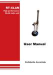
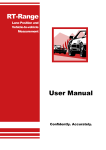
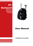
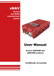
RT-UPS Uninterruptible Power Supply User Manual Confidently. Accurately. Legal Notice Information furnished is believed to be accurate and reliable. However, Oxford Technical Solutions Limited assumes no responsibility for the consequences of use of such information nor for any infringement of patents or other rights of third parties which may result from its use. No license is granted by implication or otherwise under any patent or patent rights of Oxford Technical Solutions Limited. Specifications mentioned in this publication are subject to change without notice and do not represent a commitment on the part of Oxford Technical Solutions Limited. This publication supersedes and replaces all information previously supplied. Oxford Technical Solutions Limited products are not authorised for use as critical components in life support devices or systems without express written approval of Oxford Technical Solutions Limited. All brand names are trademarks of their respective holders. Copyright Notice © Copyright 2014, Oxford Technical Solutions. Revision Document Revision: 140211 (See Revision History for detailed information). Contact Details Oxford Technical Solutions Limited 77 Heyford Park Upper Heyford Oxfordshire OX25 5HD United Kingdom Tel: +44 (0) 1869 238 015 Fax: +44 (0) 1869 238 016 Web: http://www.oxts.com Email: [email protected] 2 Oxford Technical Solutions RT-UPS User Manual Warranty Oxford Technical Solutions Limited warrants the RT-UPS product to be free of defects in materials and workmanship, subject to the conditions set forth below, for a period of one year from the Date of Sale. ‘Date of Sale’ shall mean the date of the Oxford Technical Solutions Limited invoice issued on delivery of the product. The responsibility of Oxford Technical Solutions Limited in respect of this warranty is limited solely to product replacement or product repair at an authorised location only. Determination of replacement or repair will be made by Oxford Technical Solutions Limited personnel or by personnel expressly authorised by Oxford Technical Solutions Limited for this purpose. In no event will Oxford Technical Solutions Limited be liable for any indirect, incidental, special or consequential damages whether through tort, contract or otherwise. This warranty is expressly in lieu of all other warranties, expressed or implied, including without limitation the implied warranties of merchantability or fitness for a particular purpose. The foregoing states the entire liability of Oxford Technical Solutions Limited with respect to the products herein. Revision: 140211 3 Table of contents Introduction 5 Product features 5 Description 5 Scope of delivery 7 Connecting the battery 8 Connections 11 Operation 12 LED definitions 12 Extended storage 12 RT-Range 12 Specification 14 Conformance notices 15 Regulator testing standards Safety notices Battery information Transport by sea Transport by sir Disposal / End of Life Revision history 4 15 16 16 17 17 17 18 Oxford Technical Solutions RT-UPS User Manual Introduction The RT-UPS is an uninterruptible power supply that can supply 12 V at 2 A for up to 1 minute. It has been designed specifically to overcome brown-out problems in vehicles while the engine is cranking or if the driver stalls the engine and the ignition is turned off. It is suitable for use with the Inertial+GNSS Navigation Systems from OxTS including the RT and Inertial+ series. Product features The features of the RT-UPS are: Suitable for use in vehicles. Brown-out and black-out protections during cranking or when the engine stalls. Wide input voltage range from 9 V to 48 V, including standard 12 V, 24 V and 42 V systems. Charges the battery at the same time as supplying the output. Isolated output. Transient protection for equipment. Description RT-UPS is designed to enhance the use of OxTS’s Inertial+GNSS Navigation System product range. The wide input voltage range allows use of most of the common automotive power supplies to be used, for example 12 V, 24 V and 42 V. The RT-UPS turns on when input power supply is on. If the input power supply is removed or drops too low then the RT-UPS will supply power to the output for up to 1 minute. Power is supplied from an internal battery and the output voltage is not interrupted. The RT-UPS keeps outputting a stable voltage during vehicle cranking, if the cigar socket is temporarily removed or if there are transients on the vehicle power supply. While the input power supply is absent a warning buzzer will sound and the RT-UPS will continue to supply power to the output. If the RT-UPS does not detect a load on the output then the RT-UPS will turn off immediately and the buzzer will stop. If the input power supply is restored within 1 minute then the RT-UPS will revert back to the vehicles power supply and charge the battery (if necessary). Revision: 140211 5 If the input power supply is absent for longer than 1 minute then the RT-UPS will stop the output power and the “No Power” LED will light up for up to 10 minutes. If the internal temperature of the enclosure exceeds the “over heat temperature” then output power will be turned off and the RT-UPS will enter standby for 5 minutes. It is not possible to exit this mode except by waiting 5 minutes. The RT-UPS will try to charge its internal battery whenever an input power supply is present and charging is necessary. The internal battery is protected against charging outside of its specified charging temperature range. If the battery temperature exceeds the battery “upper charging temperature” charging will be suspended until the temperature falls 5°C below the trip threshold. If the battery temperature falls below the battery “lower charging temperature” charging will be suspended until the temperature rises 5°C below the trip threshold. The internal fan will operate when the output is powered. If the battery temperature falls below “battery low temperature” the fan is temporarily switched off to avoid unnecessary further cooling of the battery which might prevent charging due to the “lower charging temperature” being reached. 6 Oxford Technical Solutions RT-UPS User Manual Scope of delivery Table 1 lists the parts that are delivered with an RT-UPS. Table 1. Summary of the components delivered with the RT-UPS Qty Description 1 RT-UPS unit 1 RT-UPS User Manual Revision: 140211 7 Connecting the battery Air transportation regulations require that battery products are disconnected while in transit. The RT-UPS will be shipped with the battery disconnected. The battery will need to be connected before the RT-UPS can be used. Before transporting the RT-UPS by air the battery should be disconnected. These instructions can be used to connect and disconnect the battery. Although the RT-UPS does not need to be opened in a full electrostatic free environment, you should take care to discharge yourself on the metal case before touching any of the internal components. To open the RT-UPS undo the four front panel screws using a No.1 Philips screwdriver as shown in Figure 1. Occasionally the two screws on the rear panel also need to be undone to remove the lid. Figure 1. Removing the front panel screws on the RT-UPS Remove the front panel and slide the lid off the RT-UPS, as shown in Figure 2. 8 Oxford Technical Solutions RT-UPS User Manual Figure 2. RT-UPS showing the battery connector Connect the battery wires to the socket on the circuit board as shown in Figure 3. The connector can only be fitted one way round; take care not to force it incorrectly. Slide the lid back in place, fit the front panel and replace the four screws. The battery will now be connected correctly. Before transporting by air disconnect the battery. The battery should only be replaced by OxTS because the temperature sensor needs to be fitted correctly. Revision: 140211 9 Figure 3. Battery connector fitted correctly 10 Oxford Technical Solutions RT-UPS User Manual Connections The RT-UPS has two leads that need to be connected for correct operation. The pin connections are shown in Table 3 and Table 4. The input power connector supplied with the RT-UPS contains a 5 A fuse, which is required as part of the input protection circuit. If the fuse in the plug needs to be replaced then it should be replaced with the Littelfuse model specified in Table 2. Table 2. Replacement fuse Parameter Specification Manufacturer Littelfuse Part Number 0214005 Description 5 A Torpedo Type Fuse Dimensions 25 x 6 mm dia Voltage Rating 36 V Table 3. Input power lead pin configuration Pin Direction Description 1 Input Power in, 9 to 48 V dc. This pin is the tip of the connector. (Red wire). 2 Input Input ground (black wire). Connector: Automotive univ fused plug (cigar lighter plug) Table 4. Output power lead pin configuration Pin Direction Description 1 Output Power output, 12 V, 2 A (brown wire). 2 Output Power output, 12 V, 2 A (white wire). 3 Output Output ground, isolated from input (blue wire). 4 Output Output ground, isolated from input (black wire). Connector: Binder Series 763, 4-way, socket, M12 Revision: 140211 11 Operation Mount the RT-UPS so that the fan and air vent holes are not covered and so that the heat can be removed from the internal components. To operate the RT-UPS, connect the output connector (Binder Series 763) to the product that needs a stable 12 V power supply. Connect the input connector (cigar plug) into the input power source. The input power supply can be disconnected at any time. To stop the output power early, disconnect the product from the output power connector. LED definitions Table 5 lists the definitions of the LEDs on the RT-UPS. As a special condition all the LEDs flash when the RT-UPS has overheated. Table 5. LED definitions LED label No power Discharging Charging Output OK Description Lit when there is no power available in the internal battery to supply the output. Lit when power is being supplied from the internal battery. Lit when charging at the standard rate. Slow flash when charging at the fast rate. Single fast flash when too cold to charge. Double fast flash when too hot to charge. Output power on. Extended storage The life of the batteries in the RT-UPS is reduced if they are left discharged for a long period of time. When leaving the RT-UPS for long periods of time it should be charged monthly. RT-Range When using the RT-UPS with the RT-Range product from OxTS care should be taken when connecting the systems. The RT-UPS should be connected between the RTRange Hunter system and the RT. It should not be connected between the power supply and the RT-Range Hunter system as the current draw will be too much and may damage the RT-UPS. Figure 4 illustrates the correct connection set up. 12 Oxford Technical Solutions RT-UPS User Manual Figure 4. Connection set-up with RT-Range Revision: 140211 13 Specification The specifications for the RT-UPS are shown in Table 6. Table 6. Specifications Parameter Input power supply Value 9 to 48 V dc Output voltage 12 V dc No load detection current 200 mA Maximum output current 2A Output power 24 W Efficiency >60% Fuse 5 A (Yellow, continental style) No supply operation up to 1 minute No supply indication up to 10 minutes Internal battery Nickel MetalHydride 12 V nominal (10 x 1.2 V cells, Varta 10V600HR) Battery charge time 1.5 hours typical Transient protection Yes Short circuit protection Yes Supply reversal protection Dimensions (mm) Weight Yes (will blow fuse) 170 x 81 x 48 (excluding cables) 0.9 kg (including cables) Operating temperature range -10° to 50ºC Internal over heat temperature 75ºC typical Upper charging temperature 65ºC typical Lower charging temperature 10ºC typical Environmental protection 14 None Oxford Technical Solutions RT-UPS User Manual Conformance notices The RT-UPS complies with the radiated emission limits for 47CFR15.109:2010 class A of Part 15 subpart B of the FCC rules, and with the emission and immunity limits for class A of EN 55022. These limits are designed to provide reasonable protection against harmful interference in business, commercial and industrial uses. This equipment generates, uses and can radiate radio frequency energy and, if not installed and used in accordance with the instructions, may cause harmful interference to radio communications. However, there is no guarantee that interference will not occur in a particular installation. If this equipment does cause harmful interference to radio or television reception, which can be determined by turning the equipment off and on, the user is encouraged to try to correct the interference by one or more of the following measures: Re-orient or relocate the receiving antenna Increase the separation between the equipment and the receiver The RT-UPS conforms to the requirements for CE. Regulator testing standards 47CFR15.109:2010 class A (radiated emissions) EN 300 440-1:2008, test methods 8.3.2 (conducted emissions) and 8.3.3 (radiated emissions) EN55022 class A according to standard EN 301 489-1:2008 (conducted emissions) EN6100-4-3 criterion A according to standard EN 301 489-1:2008 (radiated immunity) ISO7637-2 criterion B, 12V and 24V according to standard EN 301 489-1:2008 (vehicular transients and surges immunity) EN60950-1:2006 (safety) A11:2009 (safety) Revision: 140211 15 Safety notices Do not block the apertures in the box otherwise overheating will occur, which will eventually result in thermal shutdown of the device. Do not obstruct the internal fan. If the unit becomes excessively hot please unplug the device and allow it to cool. Do not replace the fuse (in the cigar lighter connector) with anything other than a 5 A fuse. If another connector is used then make sure that a 5 A fuse is included in the positive supply. Do not deliberately short circuit the outputs. Do not short circuit the internal battery. Do not throw or cause impact to the RT-UPS as it contains batteries. Do not burn. The enclosure will become warm whilst in use; allow heat to be ejected from the enclosure. Do not dispose of in domestic waste. Do not ingest the batteries. Do not allow the product to become wet or immersed in water. Recommended storage temperature 20°C. Battery information In the event of a faulty battery, a replacement can be sent out from OxTS on request along with instructions on how to change the battery for the user. The following safety information has been provided by the battery manufacturer. 1. The only battery replacement is a Varta 10V600HR (To Varta drawing no. 074530). 2. Keep out of the reach of children. If swallowed, contact a physician at once. 3. Do not reverse the battery connections. Strictly follow the signs + and – shown on batteries and appliances. If batteries are put in the wrong way they are bound to 16 Oxford Technical Solutions RT-UPS User Manual become hot very quickly. This can lead to gas or toxic material leakage and/or to a violent rupture. 4. Do not incinerate or mutilate otherwise the batteries may burst or release toxic material. Do not throw battery into open fire. This can cause violent rupture due to the heat. 5. Do not deform batteries. Batteries are not to be crushed, drilled into or damaged in any other way. This can lead to toxic material or gas leakage and/or violent rupture. 6. Do not short circuit the battery. This can lead to toxic material or gas leakage and/or violent rupture. 7. The Battery should be disposed in accordance with local and state regulations. Transport by sea For any sea transportation of nickel-metal-hydride round cells there is an additional requirement: 1. Batteries must not be stored in the near proximity of external heating sources. Transport by sir Any electrical battery or battery powered device, equipment or vehicle having the potential of a dangerous evolution of heat must be prepared for transport so as to prevent: 1. A short circuit. In the case of equipment, by disconnection of the battery and protection of exposed terminals 2. Accidental activation. The battery must be disconnected before transporting by air. Disposal / End of Life For disposal of the battery, take to local authorities recycling centre or contact OxTS for advice. The battery waste code is 160605, “Other batteries and accumulators (nickel-metal-hydride batteries)”. Revision: 140211 17 Revision history Table 7. Revision history Revision Comments 100816 Initial version (draft only) 110607 First release 130613 Updates, discharge time reduced to 1 minute 131125 Minor updates, RT-Range disclaimer 140211 Changed input power lead wire colours. Added note about replacement battery. 18 Oxford Technical Solutions