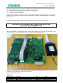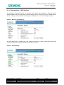
1
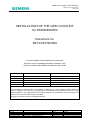
Mobility and Logistics, Traffic Solutions
Sopers Lane, Poole, Dorset
BH17 7ER
INSTALLATION OF THE GPS CLOCK KIT
for ST800/900/950
Document no.
667/CI/33190/000
THIS DOCUMENT IS ELECTRONICALLY APPROVED
AND HELD IN THE SIEMENS DOCUMENT CONTROL TOOL.
All PAPER COPIES ARE DEEMED UNCONTROLLED COPIES
Division/BU
Department
Name
Function
Prepared By
Checked and Released
Mobility and Logistics, Traffic Solutions
Engineering
D Anderson
Senior Product Engineer
Mobility and Logistics, Traffic Solutions
Engineering
D Martin
Engineering Manager
Date
03/12//2014
COPYRIGHT STATEMENT
As Meridian
The information contained herein is the property of Siemens plc. and is supplied without liability for
errors or omissions. No part may be reproduced or used except as authorised by contract or other
written permission. The copyright and the foregoing restriction on reproduction and use extend to all
media in which the information may be embodied.
Copyright
Siemens plc 2014 All Rights Reserved
Security classification
Unrestricted
Version
2
Last Editor
David Anderson
Document Name
INSTALLATION OF THE GPS CLOCK KIT
Copyright © Mobility and Logistics 2014. All Rights Reserved.
Page
1 of 16
Status
Issued
Date
03/12/2014
Document No.
667/CI/33190/000
Mobility and Logistics is a division of Siemens Plc
Mobility and Logistics, Traffic Solutions
Sopers Lane, Poole, Dorset
BH17 7ER
CONTENTS:
1
Introduction ............................................................................................................................... 3
2
Kit Contents .............................................................................................................................. 4
3
Installation of GPS Receiver Module........................................................................................ 5
4
Installation of the serial cable................................................................................................... 7
4.1
ST800 & ST900 RS232 Cable 667/1/27018/000 ............................................................ 7
4.2
ST950 RS232 cable 667/1/33191/000 .......................................................................... 8
4.3
Securing the GPS Receiver ........................................................................................... 8
5
Antenna ..................................................................................................................................... 9
6
Commissioning the GPS Clock Kit..........................................................................................10
6.1
ST900 Traffic Controller ...............................................................................................10
6.2
ST950 TRAFFIC CONTROLLER..................................................................................12
6.2.1
Web-interface – GPS Settings ......................................................................................13
6.3
System Log Detail ........................................................................................................14
7
In-Depot Testing of the GPS Clock Module ............................................................................15
8
Spares/Kits ...............................................................................................................................16
FIGURES:
Figure 1 - GPS Receiver with ST900 cable......................................................................................... 4
Figure 2 - Cabinet mounting GPS antenna with receiver ..................................................................... 4
Figure 3 - Installing the GPS receiver module - suggested location ..................................................... 5
Figure 4 – Antenna cable routing (avoiding power cables) .................................................................. 6
Figure 5 – ST800/900 RS232 Cable Connection ................................................................................ 7
Figure 6 - ST950 RS232 cable at CPU card ....................................................................................... 8
Figure 7 – Anti-vandal mounting internal view..................................................................................... 9
Figure 8 - Menu for Clock Settings ....................................................................................................13
Figure 9 - Clock Settings ...................................................................................................................13
TABLES:
Table 1 - Issue History ....................................................................................................................... 2
Table 2 – Part Numbers ..................................................................................................................... 3
CHANGE HISTORY:
Version
Date
Change
Author
A
01/01/14
Initial Draft
david.j.anderson
1
16/10/2014
TS007728
2
03/12/2014
TS007794
Table 1 - Issue History
Security classification
Unrestricted
Version
2
Last Editor
David Anderson
Document Name
INSTALLATION OF THE GPS CLOCK KIT
Copyright © Mobility and Logistics 2014. All Rights Reserved.
Page
2 of 16
Status
Issued
Date
03/12/2014
Document No.
667/CI/33190/000
Mobility and Logistics is a division of Siemens Plc
Mobility and Logistics, Traffic Solutions
Sopers Lane, Poole, Dorset
BH17 7ER
1 Introduction
The Siemens GPS Clock Kit is designed for a quick and easy installation in the Siemens traffic
controllers. It provides accurate time and date information received from the GPS satellite constellation
commonly used to provide “SATNAV” navigational position information.
Description
Part Number (Siemens Poole)
GPS CLOCK KIT ST950
667/1/33190/950
GPS CLOCK KIT ST900
667/1/33190/900
GPS ANTENNA KIT
667/1/30835/001
GPS MODULE
656/4/21410/000 (for spares)
Table 2 – Part Numbers
Other types of cabinet antenna and external pole mounted antenna are available and may be supplied in
your area. These must be fitted with an “MCX” style connector in order to be compatible with the GPS
receiver module. These are each supplied with their own installation instructions.
SAFETY NOTE – CONTROLLER UPGRADES
POWER DOWN BEFORE INSTALLING THIS KIT
Security classification
Unrestricted
Version
2
Last Editor
David Anderson
Document Name
INSTALLATION OF THE GPS CLOCK KIT
Copyright © Mobility and Logistics 2014. All Rights Reserved.
Page
3 of 16
Status
Issued
Date
03/12/2014
Document No.
667/CI/33190/000
Mobility and Logistics is a division of Siemens Plc
Mobility and Logistics, Traffic Solutions
Sopers Lane, Poole, Dorset
BH17 7ER
2 Kit Contents
The
GPS
Clock
kit
contains
3
individual
parts
shown
in
the
photographs
below.
GPS antenna designed for external cabinet mounting.
GPS receiver module in a small plastic enclosure.
Earth cable, 400mm with 2 x 5mm ring tags, securing screw, nut and washer.
Cable required to link
(ST800/ST900/ST950)
the
GPS
receiver
to
the
controller
CPU
card
Figure 1 - GPS Receiver with ST900 cable
Figure 2 - Cabinet mounting GPS antenna with receiver
.
Security classification
Unrestricted
Version
2
Last Editor
David Anderson
Document Name
INSTALLATION OF THE GPS CLOCK KIT
Copyright © Mobility and Logistics 2014. All Rights Reserved.
Page
4 of 16
Status
Issued
Date
03/12/2014
Document No.
667/CI/33190/000
Mobility and Logistics is a division of Siemens Plc
Mobility and Logistics, Traffic Solutions
Sopers Lane, Poole, Dorset
BH17 7ER
3 Installation of GPS Receiver Module
The GPS receiver is attached to the top of the swing frame with double-sided tape and cable ties with the
cabinet mounted antenna fitted in a convenient position above (installed separately).
It is important to ensure the earth strap is fitted under the antenna connector on the module
(secured by washer and nut) with the opposite end secured to an earthing point on the cabinet
chassis (as shown).
This earth connection prevents noise induced onto the outer (screen) of the coax being injected into the
GPS receiver (with subsequent loss of sensitivity and malfunction). Ensure that the antenna socket nut is
not over-tightened as this may result in failure of the antenna socket solder connections in the GPS
module.
Figure 3 - Installing the GPS receiver module - suggested location
Note that the cables should be routed downwards first to form a drip loop before rising to the antenna
and CPU card. Remove the backing strip from the adhesive tape and press the unit firmly against the
panel. Feed cable ties around the module and through the swing frame slots as shown to secure the
module.
Security classification
Unrestricted
Version
2
Last Editor
David Anderson
Document Name
INSTALLATION OF THE GPS CLOCK KIT
Copyright © Mobility and Logistics 2014. All Rights Reserved.
Page
5 of 16
Status
Issued
Date
03/12/2014
Document No.
667/CI/33190/000
Mobility and Logistics is a division of Siemens Plc
Mobility and Logistics, Traffic Solutions
Sopers Lane, Poole, Dorset
BH17 7ER
The antenna cable should be routed inside the cabinet as shown below. Do not route the cable along the
power loom as this may induce interference into the antenna cable. Excess cable should be bundled
together as shown in the picture.
Figure 4 – Antenna cable routing (avoiding power cables)
Security classification
Unrestricted
Version
2
Last Editor
David Anderson
Document Name
INSTALLATION OF THE GPS CLOCK KIT
Copyright © Mobility and Logistics 2014. All Rights Reserved.
Page
6 of 16
Status
Issued
Date
03/12/2014
Document No.
667/CI/33190/000
Mobility and Logistics is a division of Siemens Plc
Mobility and Logistics, Traffic Solutions
Sopers Lane, Poole, Dorset
BH17 7ER
4 Installation of the serial cable
The serial cable (RS232) has a 25 way D-type connector at one end and an appropriate connector for
the controller at the far end. The cable supplied is dependent upon the target controller installation.
Please read the section below as appropriate for the intended installation.
4.1
ST800 & ST900 RS232 Cable 667/1/27018/000
The ST800/900 ribbon (flat) RS232 cable is plugged into the DB25 connector on the GPS receiver unit,
and into connector X8 on the front edge of the ST800 CPU board.
NOTE: The cable must exit the X8 connector such that it leads to the rear of the controller. The coloured
wire on the ribbon cable (pin 1) must be at the bottom of the X8 connector.
Figure 5 – ST800/900 RS232 Cable Connection
Note the orientation of the cable exiting the X8 connector! Cable to the rear, with the red stripe on the
ribbon cable (pin 1) toward the bottom of the CPU board. See photograph below.
Security classification
Unrestricted
Version
2
Last Editor
David Anderson
Document Name
INSTALLATION OF THE GPS CLOCK KIT
Copyright © Mobility and Logistics 2014. All Rights Reserved.
Page
7 of 16
Status
Issued
Date
03/12/2014
Document No.
667/CI/33190/000
Mobility and Logistics is a division of Siemens Plc
Mobility and Logistics, Traffic Solutions
Sopers Lane, Poole, Dorset
BH17 7ER
4.2
ST950 RS232 cable 667/1/33191/000
The ST950 round cable is plugged into the DB25 connector on the GPS receiver unit, and into connector
PL8 on the rear of the ST950 CPU card (this is a double stacked connector, the cable plugs into the
lowest connector closest to the p.c.b. The connector is polarized with a tab in the centre of one side of
the connector. This tab may need to be shortened (with side-cutters) so that the connector fits the lower
connector.
Figure 6 - ST950 RS232 cable at CPU card
4.3
Securing the GPS Receiver
The kit is provided with 3 x 390mm long tie-wraps for the purpose of securely attaching the GPS receiver
into the cabinet. Ensure the D-type connector jack screws are fully tightened.
Use one of the provided tie-wraps to secure the serial cable to the nearest cable loom.
Use the second tie-wrap to secure any excess antenna cable.
Use the third tie-wrap around the body of the GPS module to secure it within the cabinet. This provides
additional security in the event of the adhesive tape failing.
Security classification
Unrestricted
Version
2
Last Editor
David Anderson
Document Name
INSTALLATION OF THE GPS CLOCK KIT
Copyright © Mobility and Logistics 2014. All Rights Reserved.
Page
8 of 16
Status
Issued
Date
03/12/2014
Document No.
667/CI/33190/000
Mobility and Logistics is a division of Siemens Plc
Mobility and Logistics, Traffic Solutions
Sopers Lane, Poole, Dorset
BH17 7ER
5 Antenna
The antenna is mounted on the outside of the traffic controller cabinet. This can be on the roof or side of
the cabinet for best reception of the signals from the GPS satellites, or, where the signal strength is
adequate, on the bottom of the cabinet, out of sight of pedestrians. There are separate instructions
supplied with the antenna kit which give guidance on fitting (cabinet GPS antenna 667/1/30835/001).
The antenna is mounted on the outside of the cabinet, and as such can be subjected to tampering and
vandalism. The antenna is supplied with an anti-rotation tray which when correctly installed, prevents
rotation and removal of the antenna (theft).
The ideal location of the antenna is on the top flat surface of the cabinet, but if sufficient signal strength is
available, other flat locations on the cabinet may be used.
The co-ax connector on the end of the cable marked ‘GPS’ is plugged into the corresponding connector
on the GPS Receiver enclosure. The connector is of type “MCX” and is crimped onto the cable at the
time of manufacture. If you wish to shorten the antenna coax, then you will need a new “MCX” connector
and appropriate crimping tool.
NOTE: It is not recommended that the cable is shortened unless you are able to fit the new connector
correctly, as this will cause signal loss and malfunction.
NOTE: It is possible that a dual band combined GSM and GPS antenna is provided with two cables. In
this case the GPS cable is attached to the GPS receiver, while the GSM cable goes to the wireless
modem.
Figure 7 – Anti-vandal mounting internal view
Security classification
Unrestricted
Version
2
Last Editor
David Anderson
Document Name
INSTALLATION OF THE GPS CLOCK KIT
Copyright © Mobility and Logistics 2014. All Rights Reserved.
Page
9 of 16
Status
Issued
Date
03/12/2014
Document No.
667/CI/33190/000
Mobility and Logistics is a division of Siemens Plc
Mobility and Logistics, Traffic Solutions
Sopers Lane, Poole, Dorset
BH17 7ER
6 Commissioning the GPS Clock Kit
6.1
ST900 Traffic Controller
Once the GPS Receiver has been mounted on the ST900 swing frame and the antenna coax connector
pushed into the matching connector on the GPS Receiver enclosure, the RS232 cable is connected to
the CPU card.
For ST900 the ribbon cable is plugged into the X8 connector on the front of the CPU board.
THE INSTALLATION MUST BE COMPLETED WITH THE
CONTROLLER POWERED OFF
Note the orientation of the cable exiting the X8 connector! Cable to the rear, with the red stripe on the
ribbon cable (pin 1) toward the bottom of the CPU board. See photograph below.
Connect the hand terminal (or PC running Hyperterminal) normally used to set the clock or reset the
controller, to the ST900 CPU. Power up the controller.
Enter the handset command
CKM<enter>
Security classification
Unrestricted
Version
2
Last Editor
David Anderson
Document Name
INSTALLATION OF THE GPS CLOCK KIT
Copyright © Mobility and Logistics 2014. All Rights Reserved.
Page
10 of 16
Status
Issued
Date
03/12/2014
Document No.
667/CI/33190/000
Mobility and Logistics is a division of Siemens Plc
Mobility and Logistics, Traffic Solutions
Sopers Lane, Poole, Dorset
BH17 7ER
If the GPS Receiver is connected and working correctly, the controller will display a message on the
screen of the hand terminal similar to the following:
$GPRMC,hhmmss.00,V
The ‘V’ indicates the message is NOT VALID as the GPS Receiver is still trying to tune to the GPS
satellites.
Note:
If, after entering the ‘CKM’ command the following message is displayed there is a problem with the GPS
Receiver – the controller is not receiving any data.
No GPS time data
Verify that the cable is correctly plugged into the X8 connector.
After a short while (usually less than 1 minute, but sometimes up to 3 minutes, depending on the
positions and signal strengths from the various satellites) the GPS Receiver will have tuned to the
various GPS satellites ‘in sight’ and the display will change to the following:
$GPRMC,hhmmss.00,A
The ‘hhmmss’ is the GMT (or UTC) time sent by the satellite. The ‘A’ indicates that the message is now
valid and the time it contains may be used.
The messages from the GPS Receiver are sent once per second. Note that the time is GMT (or UTC).
It is important that the date and time is first set using the ‘TOD” command in the usual way. The ST900
traffic controller ONLY uses the GPS time to ‘fine-tune’ the time in its real-time clock. That means that the
date and the hours included in the GPS message from the GPS Receiver to the ST900 controller is not
used. Only the minutes and seconds are used. This avoids problems with different time-zones across the
world. The user sets the date and time initially, and the GPS Receiver keeps it accurate thereafter.
Generally, if the power to the controller has been off for an hour or more, the controller will synchronise
its real-time clock to the incoming time from the GPS Receiver within a few seconds after the $GPRMC
messages shows the ‘A’ flag indicating a valid message.
Thereafter, the ST900 controller synchronises its real-time clock to the GPS time every 60 minutes. The
internal clock of the controller is easily capable of maintaining accurate time for the 60 minutes until the
next GPS time sync.
To see when the last GPS time sync occurred, enter the ‘CKS’ command on the hand terminal.
CKS<enter>
The display will show the date and time when the controller last synchronised its real-time clock with the
incoming GPS time.
For example:
Thu15Oct09 12:23:34
During normal operation it should always be less than 60 minutes since the controller’s clock was
synchronised with the incoming GPS time.
The traffic controller can use either the 50Hz mains frequency as its standard timebase (in between GPS
time sync’s), or the on-board crystal. The common-to-all mains frequency is usually preferred and this is
therefore the default setting in the ST900.
However, for short term accuracy the on-board crystal is a far better solution, and this option should be
selected for use with the GPS Clock.
The handset command ‘CTS’ is used for selecting the timebase.
Enter the usual command for level 2 access
PME=249<enter>
Security classification
Unrestricted
Version
2
Last Editor
David Anderson
Document Name
INSTALLATION OF THE GPS CLOCK KIT
Copyright © Mobility and Logistics 2014. All Rights Reserved.
Page
11 of 16
Status
Issued
Date
03/12/2014
Document No.
667/CI/33190/000
Mobility and Logistics is a division of Siemens Plc
Mobility and Logistics, Traffic Solutions
Sopers Lane, Poole, Dorset
BH17 7ER
Then for crystal synchronisation enter:
CTS=2<enter>
GPS Clock – Maintenance
During normal operation, the GPS Receiver continuously receives data from the GPS satellites. Provided
the signal strength is good enough, and sufficient satellites are ‘in view’, the unit sends a time message
to the ST900 controller every second. Every 60 minutes the controller synchronises its clock to the
incoming GPS time. Should the controller be switched off, or the power fail, the controller starts up using
the time in its on-board battery-backed clock, and will synchronise its time from the GPS clock within 3
minutes of power being restored (assuming the GPS unit and its antenna are operational).
As part of maintenance on the traffic controller, it is recommended to check the operation of the GPS unit
using the ‘CKM’ and ‘CKS’ commands as described above, just to ensure that the controller clock is still
being updated with the GPS time.
The ‘TOD<enter>’ command will display the date and time in the controller’s clock.
The ‘CKM<enter>’ command will display the GMT time (time only) from the satellites.
The hours of the TOD display should be 2 hours ahead of the hours in the CKM display.
The user can manually initiate a GPS time ‘sync’ by entering the following commands:
PME=249<enter>
CKS=1<enter>
The display will first show the time and date as being MON 01JAN90 00:00:00, and shortly thereafter
replace it with the (controller) time and date of the latest GPS time message.
Note that CKM displays the time from the GPS satellite as being GMT or UTC, whereas the CKS
command displays the corrected controller clock time with the time zone correction as entered by the
operator using the TOD command.
6.2 ST950 TRAFFIC CONTROLLER
The ST950 traffic controller may be configured through the web interface for operation with a GPS clock
source. The following parameters should be set for this GPS Clock Module:-
Baud Rate
4800
Data Bits
8
Stop Bits
1
Parity
N
The controller has also to be configured to use the GPS clock source, rather than the internal real time
clock.
The time messages are sent from the GPS clock module once it has acquired and locked on a sufficient
number of satellites to provide time data. Manually set the controller clock in error by half an hour and
check that the controller is corrected by the GPS clock. The correction will be recorded in the controller
log file, indicating the GPS clock module is operating correctly.
It may take five to ten minutes for the GPS receiver to acquire satellite lock and start sending time
information to the controller, depending on the number of satellites “in view” of the antenna and the
strength of the received signals.
Security classification
Unrestricted
Version
2
Last Editor
David Anderson
Document Name
INSTALLATION OF THE GPS CLOCK KIT
Copyright © Mobility and Logistics 2014. All Rights Reserved.
Page
12 of 16
Status
Issued
Date
03/12/2014
Document No.
667/CI/33190/000
Mobility and Logistics is a division of Siemens Plc
Mobility and Logistics, Traffic Solutions
Sopers Lane, Poole, Dorset
BH17 7ER
6.2.1 Web-interface – GPS Settings
The settings for enabling GPS clock can be found under “Status and Configuration”. Note that the box
marked “Default” does not make this the Default setting, rather it resets the item to the default setting.
This is confusing to anyone familiar with setting the ‘default printer’ on common desktop computers.
Figure 8 - Menu for Clock Settings
The Time Mode is set to “System Time” and “System Time Source” to GPS. This allows the GPS clock
source to provide time and date information to the traffic controller.
Figure 9 - Clock Settings
Security classification
Unrestricted
Version
2
Last Editor
David Anderson
Document Name
INSTALLATION OF THE GPS CLOCK KIT
Copyright © Mobility and Logistics 2014. All Rights Reserved.
Page
13 of 16
Status
Issued
Date
03/12/2014
Document No.
667/CI/33190/000
Mobility and Logistics is a division of Siemens Plc
Mobility and Logistics, Traffic Solutions
Sopers Lane, Poole, Dorset
BH17 7ER
6.3 System Log Detail
The following log shows the messages for a working installation and for a faulty installation.
Security classification
Unrestricted
Version
2
Last Editor
David Anderson
Document Name
INSTALLATION OF THE GPS CLOCK KIT
Copyright © Mobility and Logistics 2014. All Rights Reserved.
Page
14 of 16
Status
Issued
Date
03/12/2014
Document No.
667/CI/33190/000
Mobility and Logistics is a division of Siemens Plc
Mobility and Logistics, Traffic Solutions
Sopers Lane, Poole, Dorset
BH17 7ER
7 In-Depot Testing of the GPS Clock Module
The GPS receiver operation may be tested using a PC Laptop computer, HyperTerminal and a USB to
micro-USB cable. Disconnect the RS232 lead from the receiver module and connect the USB cable to
the laptop and the receiver. Use Hyperterminal to open the virtual serial port created when the receiver is
plugged into the laptop. It should be possible to observe the NMEA0183 format raw GPS messages from
the receiver. These start with a $ and consist of a number of lines of text.
It takes approximately two minutes for the GPS module to receive time and date with a good signal, and
up to fifteen minutes with a poor signal, depending upon the position of the satellites at the time of the
test.
Be sure to disconnect the USB cable before re-attaching the serial cable to the traffic controller.
Failure to do this may result in damage to the laptop or the GPS module.
Security classification
Unrestricted
Version
2
Last Editor
David Anderson
Document Name
INSTALLATION OF THE GPS CLOCK KIT
Copyright © Mobility and Logistics 2014. All Rights Reserved.
Page
15 of 16
Status
Issued
Date
03/12/2014
Document No.
667/CI/33190/000
Mobility and Logistics is a division of Siemens Plc
Mobility and Logistics, Traffic Solutions
Sopers Lane, Poole, Dorset
BH17 7ER
8 Spares/Kits
The following part numbers are available for GPS CLOCK installations.
Part Number
Description
667/1/33190/900
GPS CLOCK KIT ST900 (and ST800)
667/1/33190/950
GPS CLOCK KIT ST950
667/1/27018/000
GPS RS232 CABLE FOR ST800/ST900
667/1/33191/000
GPS RS232 CABLE FOR ST950
667/1/30835/001
GPS ANTENNA KIT
640/4/90018/004
GPS ANTENNA
656/4/21410/000
GPS RECEIVER MODULE
The GPS Antenna 640/4/90018/004 may be purchased to convert a GSM antenna kit 667/1/30835/000 to
a GPS kit 667/1/30835/001. This may be a useful way of minimising depot spares holdings.
When ordering kits for a controller upgrade, ensure that you order both the controller clock kit and the
antenna kit.
Security classification
Unrestricted
Version
2
Last Editor
David Anderson
Document Name
INSTALLATION OF THE GPS CLOCK KIT
Copyright © Mobility and Logistics 2014. All Rights Reserved.
Page
16 of 16
Status
Issued
Date
03/12/2014
Document No.
667/CI/33190/000
Mobility and Logistics is a division of Siemens Plc