1
Overview
2
Networking
The eNet Interface enhances the versatility of the VES fire alarm system by providing additional network
capabilities to the eLAN and Elite family of control panels.
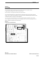
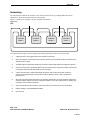
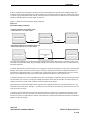
Figure 2-2 illustrates an example of an eNet using the eNet Interface:
Figure 2-2
eNet
A
CONTROL
PANEL 1
B
CONTROL
PANEL 2
CONTROL
PANEL 3
CONTROL
PANEL 4
The VES network in Figure 2-2 above supports the following functions on the eLAN or Elite Panel:
1
Cabling wired as a ring supplies eNet communication to all Panels.
2
Short circuit detection is provided at each network connection and automatic isolation is provided at the
shorted section of cable.
3
The eNet supports 1200 meters (4000 feet) of maximum cable length between two adjacent segments.
4
A short circuit at point A automatically disconnects the shorted section and a fault condition is announced
on all panels while the entire eNet continues communicating.
5
A short circuit at points A and B automatically disconnects both sections and a fault condition is
announced on all panels while communication continues between Panels 1 and 4 and between
Panels 2 and 3.
6
All Panels compute whether faults prevent an operation determined by a cause and effect configuration
and either assume inputs to be true (if configured to default to "true upon network fault") or display, print
and log the cause and effect conditions.
7
Open circuit faults allow the network to continue operating in the same way as short circuit faults.
8
Network cabling to be standard Belden RS485.
9
Up to 64 node.
VES, LLC
eNet Interface Installation Manual
VF3511-00, Revision E01.03
7 of 18