1
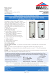
General Layout Fig: 1
EXTERNAL VIEW
KEY
1
2
3
4
5
6
7
7A
7B
8
9
10
11
12
CUTAWAY VIEW
Part No.
PLAN VIEW
KEY
Return 3/4” BSPF
Flow 3/4” BSPF
Pressure Reducing Valve
355013
Expansion valve
510505
Temperature and Pressure
Relief Valve
550853
Tundish
219002
Immersion Heater
71259
Thermostat Immersion Heater
80020
Cylinder Thermostat
80020
Cold Feed Tube
(Not supplied see Table 2)
Hot Water Outlet 3/4” BSPF
Flexible Hose
202108
Flexible Hose for Expansion Vessel
91911
Secondary Return Connection
Blanking Plug / Sensor Pocket 1/2”
13
14
15
16
17
18
19
20
21
22
23
24
25
26
Part No.
Elbow / Drain Cock
Cable Entry
Electrical Box
Tee Piece
Discharge Pipe (Not supplied)
Motorized Valve M (Not Factory Fitted)
Expansion vessel
Sensor Pocket 1/2”
Buffer vessel flow from heat pump 1”
Buffer vessel flow to heating circuit 1”
Buffer vessel return from heating circuit 1”
Buffer vessel return to heat pump 1”
Pressure Gauge Connection 1/2”
Thermostat Pocket 1/2”
250445
250006
92000
AX 19
TABLE 2
Size Lenght of tube (ø22) mm Exp. vessel pre charge
355
1020
2,5 bar
-2-