1
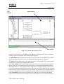
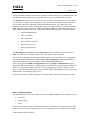
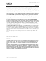
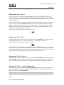
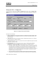
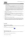
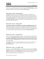
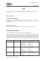
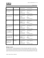
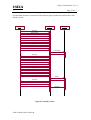
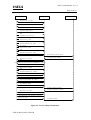
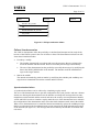
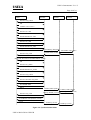
USECA
DEMONSTRATOR
USER MANUAL
Version 1.1
USECA
USECA Demonstrator V1.1: User
Page 2 of 2
Table of contents
TABLE OF CONTENTS.................................................................................................... 2
INTRODUCTION............................................................................................................... 3
INSTRUCTIONS FOR USE OF THE DEMONSTRATOR............................................. 4
INSTALLATION 4
Installation Requirements .................................................................................................. 4
Installation of the Demonstrator Application ..................................................................... 4
De-installation................................................................................................................... 4
START OF THE DEMONSTRATOR SOFTWARE .......................................................................... 5
Overview
5
Run of a Demonstration..................................................................................................... 7
THE ELEMENTS OF THE MENU ................................................................................................ 8
File-menu
8
Edit menu
10
Action Menu 12
Menu Point: Help ............................................................................................................ 15
PREDEFINED SCENARIOS ........................................................................................... 15
DEFAULT SCENARIO ............................................................................................................ 16
AUTHENTICATION SCENARIOS.............................................................................................. 18
3GPP authentication with real or simulated smart card................................................... 18
ASPeCT authentication with real or simulated smart card ............................................... 20
SIM PERSONALISATION ....................................................................................................... 21
USECA/DOC/GD/011/WP27/B
USECA
USECA Demonstrator V1.1: User
Page 3 of 3
FAILURE / FRAUD SCENARIOS............................................................................................... 23
Synchronisation failure.................................................................................................... 23
Modification of protocol messages................................................................................... 25
ASPeCT authentication procedure with man-in-the-middle attack.................................... 25
PRESENTATION EXAMPLES AND COMMENTS ..................................................... 26
COMMENTS
26
PRESENTATION EXAMPLES................................................................................................... 28
DOCUMENT MANAGEMENT....................................................................................... 29
REFERENCES
30
DEFINITIONS
31
ABBREVIATIONS .................................................................................................................. 31
General
31
Protocol Data Units, Commands, Variables .................................................................... 32
Introduction
In the demonstrator the 3GPP authentication and key agreement protocol - including the management of sequence numbers in case of synchronisation failures - and the asymmetric ASPeCT
protocol are implemented. The flows of the authentication protocols as well as the contents of the
protocol messages and the state variables of the system instances are visualised on the demonstrator screen. Therefore the demonstrator can be used as a visualisation tool in order to present the
3GPP or the ASPeCT authentication and key establishment mechanisms to an expert audience
during conferences.
Since the demonstrator allows exact tracing of the implemented authentication protocols and the
intervention of the user in order to manipulate the state variables of the system, it also serves as
an analysing tool for authentication in UMTS. The authentication and key establishment mechanisms as well as the behaviour of the protocols under failure conditions or fraud attempts can be
analysed.
Due to the time measure functions and logging functions the demonstrator may also serve as tool
for evaluating the authentication protocol as well as the performance of the implemented security
mechanisms.
USECA/DOC/GD/011/WP27/B
USECA
USECA Demonstrator V1.1: User
Page 4 of 4
Instructions for use of the Demonstrator
Installation
Installation Requirements
The following software and hardware prerequisites are required for a proper run of the USECA
demonstrator application.
•
Operating system: Windows 95 (OSR2), Windows 98 or Windows NT Version 4.0.
•
Hardware requirements:
•
Video resolution:
•
it is recommended to set the colour palette > 256 colours
•
G&D Personal Chipcard Terminal PCT200
1024*768 pixel
Installation of the Demonstrator Application
If version 1.0 of the USECA demonstrator application has already been installed on the PC or
laptop this older version has to be de-installed before the newer version 1.1 can be installed. In
order to de-install the application please refer to section 2.1.3.
The USECA demonstrator application V1.1 is delivered on 2 installation disks.
1. Insert the first installation disk.
2. Open the Control Panel Window, choose 'Software' and click on the 'Install' icon.
3. Follow the setup instructions that appear on the screen.
4. The setup routine copies the necessary data and configuration files as well as the chipcard terminal drivers to the hard disk.
5. The Demonstrator icon will be added to the Start Programs menu.
De-installation
In order to de-install the USECA demonstrator application the following tasks have to be performed:
1. Open the Control Panel Window and choose 'Software'.
2. Select Demonstrator and click on the 'Add/Remove Programs' icon.
3. The USECA demonstrator software will be removed from the hard disk after confirming the
security question.
4. Select all chipcard drivers (CHIPDRIVE) and click on the 'Add/Remove Programs' icon.
5. The chipcard terminal drivers will be removed from the hard disk.
USECA/DOC/GD/011/WP27/B
USECA
USECA Demonstrator V1.1: User
Page 5 of 5
6. A few files can not be removed automatically (Install.log, Setuptwk.exe, WProtect.exe, as
well as the configuration files and variable data files that are write protected). In order to remove these files the user has to remove the directory 'Programs\Demonstrator'.
Start of the Demonstrator Software
Overview
The USECA demonstrator application starts when the demonstrator icon in the 'Start Programs'
menu is selected, when double-clicking the icon or when the file Demonstrator.exe is executed.
A demonstration session is described within two kinds of files: a configuration file and up to 4
variable data files. When started the software first of all searches for the default configuration
and the variable data files of a UMTS system in the directory ‚Config‘. The default configuration
and variables are loaded. With these data sets the user is able to start a simulation session immediately after the start of the demonstrator application. A configuration file includes all the information that describes a simulation session like the authentication protocol or the type of the simulated attack. Configuration files and variable data files are named 'name.ext'. The extension of a
configuration file is ‚dsc‘. Variable data files are stored with the extensions ‚uvf‘, 'ivf‘, 'tvf‘, 'nvf'
which characterise the variable data files of the instances USIM, Intruder, Terminal and Network. A variable data file includes all information concerning the variables of the instance: the
name of the variable, an explanation of the variable and the current value.
After the start of the USECA demonstrator application the following screen is displayed. The
demonstrator screen includes 3 windows, a menu, a toolbar and a status line.
USECA/DOC/GD/011/WP27/B
USECA
USECA Demonstrator V1.1: User
Page 6 of 6
Tree
window
Main window
Info window
Figure 0.1: USECA demonstrator screen
All actions can be directed via the Menu. The Toolbar, positioned below the menu, includes the
symbols for the most frequently used functions of the program.
The Main Window displays the instances that are involved in the current UMTS system simulation. In this window the protocol flows of the authentication procedure are visualised.
The Title Line contains the name of the application 'USECA Demonstrator', the presently loaded
configuration and the selected authentication protocol.
In the Tree Window on the left side of the screen a tree can be seen which includes all instances
that are managed by the demonstrator. Thus the instances of the present configuration visible in
the Main Window (i.e. at the start the default configuration) are marked with blue coloured symbols. If the demonstrator application determines a physical card in the chipcard terminal, an additional symbol of a Physical USIM card is inserted into the tree. If data sets are changed manually
or during a demonstration run the corresponding symbols in the tree are marked with red colour.
In the Info Window at the bottom screen frame one can look by means of the register alternatively at the event protocol or the variables of the system instances. The user of the demonstrator
USECA/DOC/GD/011/WP27/B
USECA
USECA Demonstrator V1.1: User
Page 7 of 7
has the possibility to modify each of these variables in order to intervene in a simulation run. The
variables that are changed during a step of the simulation run are marked with red colour.
The Status Line is positioned in the left lower corner of the screen. If the user moves the mouse
over a menu or a toolbar icon an explanation of the element below the actual mouse position is
shown in this status line. Additional, during the demonstration run, the current state of the
authentication system is shown, marked with green colour. When running a simulation in Real
Time mode and selecting the action Action->Get Meas. Time the time difference between two
steps is displayed in the Status Line. In the Status Line the following types of status are shown:
•
Terminal authentication
•
CHV verification
•
AKA preparation
•
AKA (3GPP or ASPeCT)
•
Read keys from UICC
•
Secure operation mode
•
etc.
The Info Window, the Toolbar and the Status Line can be switched on or off via the menu
View. All windows are scrollable and the size of the windows can be changed.
The user has the possibility to load a predefined scenario as well as to load a new variable data
file with the help of the File menu. With the File->OpenConfiguration menu a predefined scenario can be loaded. A variable data file is loaded via the File->Load menu.
After selecting the menu Edit->Configuration the dialog Configure Demonstration appears.
Within this dialog the settings of a configuration can be modified. A simple method to change the
instances of an existing configuration is to select an existing entry in the Tree Window and to
draw it, with left mouse button pressed, into the Main Window (Drag&Drop). The instance in the
Main Window is exchanged by this process.
New instances can be created by changing an existing instance and storing it under a new name.
Run of a Demonstration
The demonstration session can be started via the menu Action-> Run. It can be started in 3 ways:
•
Real Time
•
Step By Step
•
Slow
In RealTime mode the events are illustrated in real time; that means the measured times are identically to the time of a real communication set–up. In StepByStep mode a single step of the demUSECA/DOC/GD/011/WP27/B
USECA
USECA Demonstrator V1.1: User
Page 8 of 8
onstration run is carried out each time the user presses the ‚Space‘ key. In this mode the user has
the possibility to observe the changes of the variables within a single step. The mode 'Slow' executes the simulation in a velocity which can be adjusted in the configuration menu. Thus an interruption of the demonstration session can be forced by means of the menu Action-> Break. The
run of the simulation will be continued by using the menu Action->Continue.
Each message produces an entry with the exact indication of time (1 msec resolution) into the log
file in the Info Window (lower screen frame). Measured times are real times; that means measured times include time to enter the PIN number respectively in StepByStep mode the distance
between two steps and in Slow mode the adjustment of waiting time (velocity). For this reason an
useful computation of the time distance (menu: Action->Get Meas. Time) is only possible in the
mode 'Real Time'.
By clicking onto an instance or by using the cursor keys (arrow left/right) the Info Window
switches to this instance and the variables of this instance that are relevant for the current simulation run are shown. This means that the Info Window as well as the Tree Window show a special
view of the system. Only those variables and instances are displayed which belong to the currently configured authentication protocol. I.e. in a simulation of the 3GPP protocol the variables
of the ASPeCT protocol can not be seen.
The image of the terminal simulates the visible surface of the terminal. Via its display the terminal user will be required to enter his PIN number. Error messages will also occur on the display,
e.g. in case of a missing USIM card. The input of the PIN number will be carried out via the keyboard of the terminal, whereas the input will be followed up with '****' as it is done with a physical device.
Note: If the input length is lower than 8 digits the user has to confirm his input with the ‘OK’
Button.
The elements of the menu
File-menu
The standard loading and saving functions of the demonstrator application load the relevant files
from the directory 'Config'. They also save the relevant files into this predefined directory. The
directory 'Config' contains all the information concerning the configuration and variable data
files.
Besides the standard possibilities of saving and loading configurations the demonstrator application provides a mechanism to import and export configurations. In contrary to ‘normally’ saving
both configuration files and variable data files can be exported to another directory or disk or imported from another directory or disk. In this way configurations can be used without additionally
settings in every further version of the demonstrator software.
USECA/DOC/GD/011/WP27/B
USECA
USECA Demonstrator V1.1: User
Page 9 of 9
Menu point: File ->Load
After the selection of the menu point File->Load a dialog opens up which enables the user to
choose variable files. If one entry in the Tree Window is selected, the dialog opens up with the
corresponding extension. When the dialog is closed with OK, the application checks whether this
entry already exists.
In case that this file does not exist yet within the working store of the demonstrator, a new entry is
created in the tree of the Tree Window. If the file already exists in the tree, a security inquiry
appears 'Overprint the old file' with ‘Yes’, ‘No’ and ‘Cancel. If ‘Yes’ is selected, the variable
data file of the old entry is overwritten within the working store of the demonstrator. If ‘No’ or
‘Cancel’ is selected, this process is cancelled.
This action can also be carried out via the toolbar Icon
Menu point: File ->Save
This menu point is only active if an entry is selected in the Tree Window. The features for the
selected entry are stored in a variable data file (name + corresponding extension).
This action can also be carried out via the toolbar Icon
Note: In order to avoid unintentional modifications of the predefined scenarios the user is highly
recommended to write-protect the configuration files and variable data files that are corresponding to the predefined scenarios. These files that are stored in the directory \Config. Files that are
write-protected can be stored under a new name with the menu File->Save As.
Menu point: File ->Save As
This menu point is only active if an entry is selected in the Tree Window. After selection of the
menu point File->Save As a dialog is opened up and the user is requested to enter a name for this
entry. The features for the selected entry are stored in a file with the corresponding extension.
Menu point: File -> Open Configuration
After selection of the menu point File->Open Configuration a window opens up in which the
user can choose between several predefined configuration files. After closing the dialog the configuration is shown in the Main Window.
With this function only the configuration file which contains the information concerning the configuration settings is loaded while the variables of the instances of the configuration are not modified. In order to reload the original variables of the instances the menu File->Load has to be selected.
USECA/DOC/GD/011/WP27/B
USECA
USECA Demonstrator V1.1: User
Page 10 of 10
Menu point: File -> Save Configuration
The configuration is stored as a file (file format: Name.dsc)
Menu point: File -> Close Configuration
The present configuration is closed and the default configuration is loaded.
Menu point: File -> Import
The configuration file and the corresponding variable data files are loaded from any data media
or from any directories.
Menu point: File -> Export
The present configuration can be exported onto another data medium. The demonstrator application stores not only the configuration file but also the corresponding variable data files.
Menu point: File -> Recent Files
Up to four of the last loaded configurations are shown here and can be activated by selecting the
application.
Menu point: File -> Exit
After a security request the state of the software, i.e. the last visible windows and their dimensions are recorded in the registration data base. With a new start the software appears with these
windows again.
The demonstrator software is closed.
Edit menu
Menu point: Edit -> Delete Entity
Only active, if an entry is selected in the Tree Window.
The selected entry is deleted after a double security request in the tree as well as in the directory
‘Config’. This process is irrevocable after the statement of the security requests.
USECA/DOC/GD/011/WP27/B
USECA
USECA Demonstrator V1.1: User
Page 11 of 11
Menu point: Edit -> Configuration
After the selection of the menu point Edit->Configuration the dialog window Configure Demonstration opens up. When this dialog is opened the currently loaded configuration settings are
shown.
Figure 0.2: Configure Demonstration Window
Description of the Elements:
•
Smart Card Mode: The user can choose between a virtual and a physical card. This action
can also be carried out by Drag&Drop from the Tree Window into the Main Window. (Default: Simulated)
•
Abstraction Level: The user can choose between a detailed and an abstract view of the protocol message flows. (Default: Abstract)
•
Authentication Protocol: The user can choose between the 2 authentication protocols 3GPP
and ASPeCT. (Default: 3GPP)
•
Fraud Simulation: The user may choose between 2 types of fraud simulation, Eavesdrop/Modify and Man in the middle. (Fraud mode default: No Intruder selected)
•
Eavesdrop / modify (3GPP, ASPeCT): The intruder is able to eavesdrop, store and modify messages that are exchanged between the terminal and the network. The intruder only
eavesdrops and stores the messages automatically. He does not modify the messages
automatically. The user of the demonstrator has the possibility to modify the messages by
modifying the data in the SEND_MESS buffer of the intruder. The intruder sends the
modified messages to the target instance.
•
Man-in-the-middle: In this fraud simulation mode the intruder automatically modifies
messages that are transmitted between the network and the terminal. He automatically
USECA/DOC/GD/011/WP27/B
USECA
USECA Demonstrator V1.1: User
Page 12 of 12
performs attacks.
When the 3GPP protocol is simulated, the intruder replays authentication messages that
have been eavesdropped in former authentication sessions. Notice: To run a simulation in
this mode a session in Eavesdrop/Modify mode has to be started first. In this way the intruder is able to eavesdrop the necessary data. When the ASPeCT protocol is simulated
the intruder possesses a public key pair and a certificate and manipulates the communication between the terminal and the network. When receiving an authentication message he
analyses the message and modifies it by the use of his own keys and certificate. He sends
the modified messages to the target party. His goal is to impersonate the network in
communications with the terminal and to impersonate the terminal in communications
with the network.
•
Velocity: Setting of the holding time for one step in Slow mode. This field may include values between: 1...100 s. (Default: 1s)
•
Configuration: This field allows the user to compose a demonstrator configuration. If a
physical card is chosen, the field USIM is inactive; otherwise the user has to choose a card
in this field. This action can also be carried out by Drag&Drop from the configuration window into the Main Window.
•
OK: A new temporary configuration is created and shown in the Main Window. The dialog
is left.
•
Cancel: The dialog is left without any changes.
•
Com Port: After pressing this button the dialog window Com Port opens up. This dialog
allows the user to select the interface for the chipcard terminal. After changing the adjusted
interface the demonstrator application checks automatically whether a chipcard terminal can
be found at the new interface. This action lasts up to a few seconds. (Default: Com2)
Action Menu
Menu Point: Run -> Real Time
When the menu point Action Run->Real Time is selected the demonstration is started in the Real
Time mode.
This action can also be carried out with the toolbar Icon
Menu Point: Run -> Slow
The menu point Action Run->Slow starts the demonstration in Slow mode with the adjusted velocity.
This action can also be carried out with the toolbar Icon
USECA/DOC/GD/011/WP27/B
USECA
USECA Demonstrator V1.1: User
Page 13 of 13
Menu Point: Run -> Step By Step
After selection of the menu point Action Run-> Step By Step the demonstration is started in the
Slow mode. In this simulation mode the user has to press the ‚Space‘ key to proceed a single step.
This action can also be carried out via the toolbar Icon
Menu Point: Action -> Break
This menu point is only active if a simulation is started in slow mode. When selecting the menu
point Action-> Break the demonstration stops and the menu item changes in Continue. By using
the menu point Action->Continue or pressing the toolbar item Slow the run of the demonstration
will be continued.
This action can also be carried out via the toolbar Icon
Menu Point: Action -> Stop
The menu Stop is only active if a simulation is started. Via the menu point Action->Stop the
demonstration is stopped.
This action can also be carried out via the toolbar Icon
Menu Point: Action -> Personalise
By using the SIM personalisation feature the user is able to lock one terminal to one or more (up
to 3) different USIMs. After the personalisation the terminal works only with the personalised
cards. When the menu point Action ->Personalise is selected the picture of a terminal appears.
The user has to enter the personalisation key in order to activate the personalisation feature. The
input of the PIN number will be carried out via the keyboard of the handy or via the keyboard of
the PC.
USECA/DOC/GD/011/WP27/B
USECA
USECA Demonstrator V1.1: User
Page 14 of 14
In case of a new personalisation the user has to enter his 4 digit Personalisation Key and confirm
this key. The terminal uses the identity number of the USIM card as the personalisation code. For
any further personalisation the user has to enter the Personalisation Key.
Menu Point: Action -> De-Personalise
This function allows the user to unlock the terminal. When the menu point Action ->DePersonalise is selected the picture of the terminal appears and the user is asked to enter the Personalisation Key. The input of this PIN number will be carried out via the keyboard of the terminal or via the keyboard of the PC. In order to de-personalise a terminal the user has to enter the
Personalisation Key which has been entered during the personalisation procedure (via the Action
menu Action ->Personalise). If the input of the key is correct the personalisation data as well as
the Personalisation Key are deleted.
Menu Point: Action -> Change CHV
The card holder verification value (PIN number) of a physical or a simulated smart card can be
changed via this function. By selecting the menu point Action ->Change CHV the picture of a
terminal appears and the user has to enter his PIN number. The input of the PIN number will be
carried out via the keyboard of the handy or via the keyboard of the PC. At first the user has to
enter the old PIN number. Afterwards he has to enter the new PIN number and confirm this entry.
In a simulated card the new PIN number appears in the directory DF_UMTS/EF_CHV.
Menu Point: Action -> Unblock CHV
In case of a wrong input of the PIN number more than 3 times the CHV number is blocked. Now
the user has to use the Unblock CHV functionality in order to annul this state. When the menu
point Action ->Unblock CHV is selected the picture of a terminal appears. The input of the PIN
number will be carried out via the keyboard of the handy or via the keyboard of the PC. At first
the user has to enter the Unblock CHV number. Afterwards he has to enter the new PIN number
and confirm this input.
If the Unblock CHV Action is successful both the counter of the CHV and the counter of Unblock CHV will be reset. In a simulated card all these variables appear in the directory
DF_UMTS/EF_CHV.
Menu Point: Action -> Get Meas. Time
Only active, if a simulation Real Time has been started before. After the menu point Action Get
Meas. Time is chosen the user is requested to press the 'Shift' key and select entries in the Main
Window with the mouse or in the Info Window ,Log Book’ with mouse and keyboard. The time
difference in milliseconds between first and last selected entry is shown in the status line.
This action can also be carried out via the toolbar Icon
USECA/DOC/GD/011/WP27/B
USECA
USECA Demonstrator V1.1: User
Page 15 of 15
This process is stopped by selecting the Action->Get Meas. Time menu or pressing the icon
once more.
Menu Point: Help
Menu Point: Help Topics
After selection of the menu point Help Topics the online help functions of the demonstrator application opens up. Via the card index ‘Contents’, ‘Index’ or ‘Search’ an Online – Help is at the
user’s disposal.
Menu Point: About
The version number of the application is shown together with the icon in a dialog field.
Predefined scenarios
The USECA demonstrator offers the possibility to run predefined scenarios.
The configuration settings as well as the values of the instance variables are described in a format
that has been defined specifically for the demonstrator. The configuration information is stored in
demonstration scenario configuration files (name.dsc). The instance variables are stored in entity
variables files (name.uvf/.tvf/.nvf/.ivf). With the use of these files it is possible to predefine scenarios that can be loaded and run easily. The following table gives an overview of predefined scenarios:
scenario
configuration
comments
default scenario
default.dsc
Smart card mode:
Network protocol:
Velocity:
Abstraction Level:
Fraud Simulation:
simulated smart card
3GPP protocol
1s
abstract
no fraud attempts
3GPP authentica- 3gpp_realcard.ds Smart card mode:
tion with real smart c
Network protocol:
card
Velocity:
Abstraction Level:
Fraud Simulation:
physical smart card
3GPP protocol
1s
detailed
no fraud attempts
ASPeCT authentication with real
smart card
physical smart card
ASPeCT protocol
1s
detailed
asSmart card mode:
pect_realcard.dsc Network protocol:
Velocity:
Abstraction Level:
USECA/DOC/GD/011/WP27/B
USECA
USECA Demonstrator V1.1: User
Page 16 of 16
Abstraction Level:
Fraud Simulation:
detailed
no fraud attempts
3GPP authentication with simulated
smart card
3gpp_simcard.ds Smart card mode:
c
Network protocol:
Velocity:
Abstraction Level:
Fraud Simulation:
simulated smart card
3GPP protocol
1s
detailed
no fraud attempts
ASPeCT authentication with simulated smart card
asSmart card mode:
pect_simcard.dsc Network protocol:
Velocity:
Abstraction Level:
Fraud Simulation:
simulated smart card
ASPeCT protocol
1s
detailed
no fraud attempts
SIM personalisation
personalisation.dsc
Smart card mode:
Network protocol:
Velocity:
Abstraction Level:
Fraud Simulation:
simulated smart card
3GPP protocol
1s
detailed
no fraud attempts
synchronisation
failure between the
USIM and the network
synch_fail.dsc
Smart card mode:
Network protocol:
Velocity:
Abstraction Level:
Fraud Simulation:
simulated smart card
3GPP protocol
1s
detailed
man-in-the-middle
intruder modifies
protocol messages
of the 3GPP authentication procedure
3gpp_modify.dsc Smart card mode:
Network protocol:
Velocity:
Abstraction Level:
Fraud Simulation:
simulated smart card
3GPP protocol
1s
detailed
eavesdrop/modify
intruder modifies
protocol messages
of the ASPeCT authentication procedure
aspect_modify.dsc
Smart card mode:
Network protocol:
Velocity:
Abstraction Level:
Fraud Simulation:
simulated smart card
ASPeCT protocol
1s
detailed
eavesdrop/modify
ASPeCT authentication procedure
with man-in-themiddle-attack
aspect_man-i-tmiddle.dsc
Smart card mode:
Network protocol:
Velocity:
Abstraction Level:
Fraud Simulation:
simulated smart card
ASPeCT protocol
1s
detailed
man-in-the-middle
Default scenario
The default scenario is loaded automatically when the demonstrator application is started. This
scenario describes a 3GPP authentication process with a simulated smart card. The messages that
are transmitted between the instances are characterised by their names (without parameters). The
instances Def_Usim, Def_Term and Def_Net are involved in the authentication process. The SIM
USECA/DOC/GD/011/WP27/B
USECA
USECA Demonstrator V1.1: User
Page 17 of 17
personalisation function is switched off. The following figure explains the protocol flow of the
default scenario.
USIM
Terminal
Network
SELECT
VERIFY CHV
SELECT
READ BINARY
SELECT
READ BINARY
InitAuthReq
AuthMechAck
SELECT
MANAGE SECURITY ENVIRONMENT
SELECT
READ BINARY
SELECT
SELECT
ENCIPHER IMSI
AuthID
AuthReq
SELECT
AUTHENTICATE
AuthResp
Figure 0.1: Default scenario
USECA/DOC/GD/011/WP27/B
USECA
USECA Demonstrator V1.1: User
Page 18 of 18
Authentication scenarios
3GPP authentication with real or simulated smart card
The scenario '3GPP authentication with real smart card' is stored in the configuration file
'3gpp_realcard.dsc'. The configuration file '3gpp_simcard' describes the settings that are necessary for the run of a 3GPP authentication process with a simulated smart card. In both cases the
SIM personalisation function is switched off. See the following figure for a detailed description of
the protocol flows.
USECA/DOC/GD/011/WP27/B
USECA
USECA Demonstrator V1.1: User
Page 19 of 19
USIM
Terminal
Network
SELECT DF_UMTS
OK
VERIFY CHV (CHV1)
OK
SELECT EF_SPN
OK
READ BINARY EF_SPN
EF_SPID
SELECT EF_SSD
OK
READ BINARY EF_SSD
EF_SSD
InitAuthReq (SPID | SSD)
SELECT DF_3GPP
AuthMechAck (3GPP)
OK
MANAGE SECURITY ENVIRONMENT (3GPP)
OK
SELECT EF_GMSI
OK
READ BINARY EF_GMSI
EF_GMSI
SELECT DF_UMTS
OK
SELECT BINARY EF_IMSI
OK
ENCIPHER IMSI
EMUI
AuthID (GMSI | EMUI)
AuthReq (RAND | AUTN)
SELECT DF_3GPP
OK
AUTHENTICATE (RAND | AUTN)
RES | CK | IK
AuthResp (RES)
Figure 0.2: 3GPP authentication (detailed view)
USECA/DOC/GD/011/WP27/B
USECA
USECA Demonstrator V1.1: User
Page 20 of 20
ASPeCT authentication with real or simulated smart card
In order to visualise the ASPeCT authentication procedure one of the configuration files 'aspect_realcard.dsc' or 'aspect_simcard.dsc' has to be opened.
USIM
Terminal
Network
SELECT DF_UMTS
OK
VERIFY CHV (CHV1)
OK
SELECT EF_SPID
OK
READ BINARY EF_SPID
EF_SPID
SELECT EF_SSD
OK
READ BINARY EF_SSD
EF_SSD
InitAuthReq (SPID|SSD)
SELECT DF_ASPeCT
OK
AuthMechAck (ASPeCT)
MANAGE SECURITY ENVIRONMENT (ASPeCT)
OK
GENERATE PUBLIC KEY PAIR
PK_U
SELECT EF_CAID
OK
READ BINARY EF_CAID
EF_CAID
AuthChall (PK_U | CAID)
AuthReq (RND_N | AUTH_N | CERTN)
VERIFY CERTIFICATE (CERTN)
OK
MUTUAL AUTHENTICATE (RND_N|AUTH_N)
Enc(Sig(AUTH_U))
SELECT EF_CERTU
OK
SECURE READ BINARY EF_CERTU
Enc(EF_CERTU)
AuthResp (Enc(Sig(AUTH_U)) | Enc(CERTU))
SELECT DF_UMTS
OK
SELECT EF_CK
OK
READ BINARY EF_CK
EF_CK
SELECT EF_IK
Ok
READ BINARY EF_IK
EF_IK
Figure 0.3: ASPeCT authentication
USECA/DOC/GD/011/WP27/B
USECA
USECA Demonstrator V1.1: User
Page 21 of 21
SIM Personalisation
When the USIM Personalisation Indicator (UPI) of the terminal is set to 'on' the terminal selects
the EF_UICCID and reads the UICCID. It compares this identifier with the reference values
stored in the terminal. In case of a match the USIM is accepted and the authentication and key
establishment procedure is executed (see figure 3.4). Otherwise the message 'Please insert correct
USIM' is announced and the terminal switches into the mode where only emergency calls are allowed (see figure 3.5)
USECA/DOC/GD/011/WP27/B
USECA
USECA Demonstrator V1.1: User
Page 22 of 22
USIM
Terminal
Network
SELECT EF_ICCID
OK
READ BINARY EF_ICCID
EF_ICCID
SELECT DF_UMTS
OK
VERIFY CHV (CHV1)
OK
SELECT EF_SPN
OK
READ BINARY EF_SPN
EF_SPID
SELECT EF_SSD
OK
READ BINARY EF_SSD
EF_SSD
InitAuthReq (SPID | SSD)
SELECT DF_3GPP
AuthMechAck (3GPP)
OK
MANAGE SECURITY ENVIRONMENT (3GPP)
OK
SELECT EF_GMSI
OK
READ BINARY EF_GMSI
EF_GMSI
SELECT DF_UMTS
OK
SELECT BINARY EF_IMSI
OK
ENCIPHER IMSI
EMUI
AuthID (GMSI | EMUI)
AuthReq (RAND | AUTN)
SELECT DF_3GPP
OK
AUTHENTICATE (RAND | AUTN)
RES | CK | IK
AuthResp (RES)
Figure 0.4: Correct SIM personalisation
USECA/DOC/GD/011/WP27/B
USECA
USECA Demonstrator V1.1: User
Page 23 of 23
USIM
Terminal
Network
SELECT EF_ICCID
OK
READ BINARY EF_ICCID
EF_ICCID
Figure 0.5: SIM personalisation failure
Failure / fraud scenarios
The USECA demonstrator offers the possibility to simulate fraud attempts and to study the behaviour of the UMTS system in the case of failure or fraud. The demonstrator includes two different fraud simulation modes:
•
•
Eavesdrop / modify:
•
The intruder automatically eavesdrops and stores the messages that are exchanged between the terminal and the network. He does not modify the messages automatically.
•
The user of the demonstrator has the possibility to modify the messages by modifying the
data in the SEND_MESS buffer of the intruder. The intruder sends the modified messages to the target instance
Man in the middle:
The intruder automatically performs attacks by modifying the AuthReq and AuthResp messages that are transmitted between the terminal and the network.
Synchronisation failure
A synchronisation failure can be achieved by simulating a replay attack.
The user of the demonstrator has to open the configuration file 'synch_fail.dsc' and start a demonstration run. During this demonstration run the intruder eavesdrops the messages that are transmitted between the terminal and the network and stores the security relevant parameters RAND,
AUTN and RES. In order to simulate a replay attack the user of the demonstrator has to enhance
the configuration of the demonstrator and to select the fraud simulation mode 'man in the middle'.
When a new demonstration run is started the intruder automatically replays the AuthReq message
that he eavesdropped in the last authentication session instead of the fresh authentication request
of the network (see figure 3.6). The messages that are modified by the intruder are marked with
red colour.
USECA/DOC/GD/011/WP27/B
USECA
USECA Demonstrator V1.1: User
Page 24 of 24
USIM
Terminal
Intruder
Network
SELECT DF_UMTS
OK
VERIFY CHV (CHV1)
OK
SELECT EF_SPN
OK
READ BINARY EF_SPN
EF_SPID
SELECT EF_SSD
OK
READ BINARY EF_SSD
EF_SSD
InitAuthReq (SPN| SSD)
InitAuthReq (SPN| SSD)
AuthMechAck (3GPP) AuthMechAck (3GPP)
SELECT DF_3GPP
OK
MANAGE SECURITY ENVIRONMENT (3GPP)
OK
SELECT EF_GMSI
OK
READ BINARY EF_GMSI
EF_GMSI
SELECT DF_UMTS
OK
SELECT BINARY EF_IMSI
OK
ENCIPHER IMSI
EMUI
AuthID (GMSI | EMUI)
AuthReq (RAND | AUTN)
SELECT DF_3GPP
AuthID (GMSI | EMUI)
AuthReq (RAND | AUTN)
OK
AUTHENTICATE (RAND | AUTN)
AUTS
AuthResp (AUTS)
Figure 0.6: Synchronisation failure
USECA/DOC/GD/011/WP27/B
AuthResp (AUTS)
USECA
USECA Demonstrator V1.1: User
Page 25 of 25
Modification of protocol messages
If the user of the demonstrator wants to modify the protocol messages he may open the configuration '3gpp_modify.dsc'. With this configuration the intruder eavesdrops and stores the messages
that are sent from the network to the terminal and vice versa. The intruder stores the messages
that he receives from the sender of the message in the buffer REC_MESS. This message is copied
into the SEND_MESS buffer. The user of the demonstrator has the possibility to modify the message in the SEND_MESS buffer. With the following simulation step the intruder sends the message that is stored in the SEND_MESS buffer to the destination party.
ASPeCT authentication procedure with man-in-the-middle attack
The configuration file 'aspect_man-i-t-middle.dsc' may be used in order to simulate a man in the
middle attack where the intruder automatically attacks the ASPeCT authentication procedure.
The intruder possesses a public key pair and a certificate and manipulates the communication
between the terminal and the network. When receiving an authentication message the intruder
analyses the message and modifies it by the use of his own keys and certificate. He sends the
modified messages to the target party. His goal is to impersonate the network in communications
with the terminal and to impersonate the terminal in communications with the network (see figure
3.7).
USECA/DOC/GD/011/WP27/B
USECA
USECA Demonstrator V1.1: User
Page 26 of 26
USIM
Terminal
Intruder
Network
SELECT DF_UMTS
OK
VERIFY CHV (CHV1)
OK
SELECT EF_SPID
OK
READ BINARY EF_SPID
EF_SPID
SELECT EF_SSD
OK
READ BINARY EF_SSD
EF_SSD
InitAuthReq (SPID|SSD)
InitAuthReq(SPID|SSD)
AuthMechAck(ASPeCT)
AuthMechAck (ASPeCT)
SELECT DF_ASPeCT
OK
MANAGE SECURITY ENVIRONMENT (ASPeCT)
OK
GENERATE PUBLIC KEY PAIR
PK_U
SELECT EF_CAID
OK
READ BINARY EF_CAID
EF_CAID
AuthChall (PK_U|CAID)
AuthChall(PK_U|CAID)
AuthReq(RND_N|AUTH_N|CERTN)
AuthReq (RND_N|AUTH_N|CERTN)
VERIFY CERTIFICATE (CERTN)
OK
MUTUAL AUTHENTICATE (RND_N|AUTH_N)
USIM_AUTH_FAILED
USIM_AUTH_FAILED
USIM_AUTH_FAILED
Figure 0.7: Man-in-the-middle attack (ASPeCT protocol)
Presentation examples and comments
Comments
PIN
USECA/DOC/GD/011/WP27/B
USECA
USECA Demonstrator V1.1: User
Page 27 of 27
PIN (CHV1) = 0000
Unblock PIN (Unblock CHV1) = 0000 0000
•
The user PIN „0000“ is entered
•
either with the mouse via the keyboard of the terminal and confirmed with ‚OK‘
•
or via the keyboard of the laptop/PC and confirmed with the ‚Return‘ key.
•
The user has the possibility to change the PIN via the menu point Action -> Change
CHV.
•
If a false PIN is entered more that 3 times the PIN is blocked. The PIN can be unblocked
with the menu point Action -> Unblock CHV. The unblocking PIN „00000000“ has to
be entered.
Start of a demonstration run: there are three possible modes:
•
Realtime-Mode: Toolbar -> arrow or via the menu point Action -> Run -> Realtime
•
Slow-Mode: Toolbar -> 2 arrows
or via the menu point Action -> Run -> Slow
•
Step-by-Step: Toolbar -> arrow with line
or via the menu point Action -> Run -> Step-by-Step
Counter synchronisation in case of the 3GPP protocol with real smart card
•
When the demonstrator application is started a loss of synchronisation between the
counter in the real smart card and the network may occur. In this case the smart card delivers the response data ‘AUTS’ after the AUTHENTICATE command. This is not a
faulty behaviour and the synchronisation between the smart card and the network will be
proceeded automatically.
•
Explanation: the sequence counters in the network are loaded from the variable data file
at each start of the demonstrator application. The counter in the real smart card keeps its
current value when the smart card is reset.
•
In order to ensure the synchronisation of the counters at a new start of the demonstrator
application the variables of the network have to be stored before the demonstrator application is exited:
•
the network instance (e.g. Net_3) that shall be used in further demonstration runs
with a real smart card has to be selected in the Tree Window with the use of the left
mouse button
•
via the menu point File -> Save the variables of the network are stored
USECA/DOC/GD/011/WP27/B
USECA
USECA Demonstrator V1.1: User
Page 28 of 28
Presentation examples
3GPP Authentication
1. Open the configuration
– with simulated smart card: File -> Open Configuration ‘3gpp_simcard.dsc’
– with real smart card: File -> Open Configuration ‘3gpp_realcard.dsc’
2. Start the demonstrations run
3. Enter the PIN – ‘0000’
4. Proceed the demonstration until the authentication procedure is finished.
Ø The demonstration run will be finished with the status ‘Secure Operation Mode’.
Replay Attack (short version)
1.
2.
3.
4.
Open the configuration: File -> Open Configuration ‘synch_fail.dsc’
Start the demonstrations run
Enter the PIN – ‘0000’
Proceed the demonstration until the authentication procedure is finished
Ø the intruder eavesdrops the message AuthReq(RAND|AUTN) and stores the parameters
Ø The demonstration run will be finished with the status ‘Secure Operation Mode’, since
the intruder did not modify any messages.
5. Enhance the configuration in order to simulate a replay attack:
Edit -> Configuration -> Fraud Simulation ‘Man in the middle’
confirm with OK
6. Start a new demonstrations run
Ø The intruder modifies the message that he received from the network. Instead of the
original AuthReq / AuthRes messages the intruder sends the parameters of the corresponding messages that have been eavesdropped in the former protocol run.
Ø The USIM checks the authentication parameters and detects the replay attack. The smart
card delivers the response parameters ‘AUTS’ and a ‘Authentication failure’ is announced by the network. The demonstrations run is stopped.
Replay Attack (detailed version)
1.
2.
3.
4.
Open the configuration: File -> Open Configuration ‘synch_fail.dsc’
Start the demonstrations run.
Enter the PIN – ‘0000’
Break the demonstrations run when the intruder receives the message AuthReq(RAND|AUTN) that was sent by the network:
Ø The intruder eavesdrops the message and stores the parameters RAND and AUTN,
the variables are stored in Def_Int\eavesdropped_auth_data (see Tree Window)
5. Continue the demonstrations run until the protocol run is finished:
USECA/DOC/GD/011/WP27/B
USECA
USECA Demonstrator V1.1: User
Page 29 of 29
6.
7.
8.
9.
10.
11.
Ø The demonstrations run will be finished with the status ‘Secure Operation Mode’, since
the intruder did not modify any messages
Enhance the configuration in order to simulate a replay attack:
Edit -> Configuration -> Fraud Simulation ‘Man in the middle’
confirm with OK
Start a new demonstrations run
Break when the terminal received the message AuthReq(RAND|AUTN) that was sent by the
intruder.
Compare the message that was sent by the network with the message that was modified and
sent by the intruder (click on the corresponding messages with the left mouse button, the message contents are displayed in the Info Window)
Ø The intruder modifies the message that he received from the network. Instead of the
original message of the network the intruder sends the parameters of the message that
have been eavesdropped in the former protocol run to the terminal.
Continue the demonstrations run:
Ø The USIM detects the replay attack and delivers the response message AUTS;
Ø A ‘Authentication failure’ is announced;
Ø the demonstrations run is stopped
In order to show that the 3GPP system functions correctly even after a replay attack the intruder can be switched off afterwards and a new demonstrations run (without intruder) can be
started.
User of the demonstrator modifies messages
1.
2.
3.
4.
Open configuration: File -> Open Configuration ‘3gpp_modify.dsc’
Start the demonstrations run.
Enter the PIN ‘0000’.
Break the demonstrations run when the intruder receives the message AuthReq(RAND|AUTN) that was sent by the network
5. Select the variables: Intruder\Def_Int\Message_buffers in the Tree Window
Ø In the Info Window two buffers are displayed:
- REC_MESS includes the message that was received by the intruder
- SEND_MESS includes the message that the intruder will send to the terminal
6. The user has the possibility to modify the message in the SEND_MESS buffer:
- click in the value column of the line send mess
- overwrite any characters of the message
- confirm with ‘OK’
7. Continue the demonstrations run
Ø The USIM detects that the authentication data of the network are not correct and announces an error (Authentication failed)
Ø The demonstrations run is stopped
Document Management
Author:
Monika Horak,
Giesecke & Devrient,
Prinzregentenstr. 159, D-81677 München, Germany
USECA/DOC/GD/011/WP27/B
USECA
USECA Demonstrator V1.1: User
Page 30 of 30
Phone: +49 89 4119 1944 / Fax: +49 89 4119 2460,
Email: [email protected]
Reference:
Version:
USECA\DOC\GD\011\WP27\B
V1.1 / 15th August 2000
References
[3G21.111]
3G TS 21.111 3rd Generation Partnership Project; Technical Specification
Group Terminals, USIM and IC Card Requirements, Version 3.0.0, 1999
[3G31.101]
3GPP 31.101 3rd Generation Partnership Project; Technical Specification
Group (TSG) Terminals; UICC Physical and Logical Characteristics; Version
0.5.0, 1999
[3G31.102]
3G TS 31.102 3rd Generation Partnership Project; Technical Specification
Group Terminals; USIM characteristics, Version 0.5.0, 1999
[3G33.102]
3G TS 33.102 3rd Generation Partnership Project; Technical Specification
Group Services and System Aspects; 3G Security; Security Architecture, Version 3.0.0, 1999
[ASP-D20]
1999
ACTS ASPeCT AC095 deliverable 20, Project final report and results of trials,
[GSM02.16]
GSM 02.16 Digital cellular telecommunications system (Phase 2+); International
Mobile station Equipment Identities (IMEI); Version 6.0.0 Release 1997
[GSM02.22]
GSM 02.22 Digital cellular telecommunications system (Phase 2+); Personalisation of GSM Mobile Equipment (ME); Mobile functionality specification; Version 6.0.0 Release 1997
[GSM11.11]
GSM 11.11 Digital cellular telecommunications system (Phase 2+); Specification of the Subscriber Identity Module - Mobile Equipment (SIM - ME) interface, Version 7.2.0 Release 1998
[HP98]
Günther Horn, Bart Preneel: Authentication and Payment in Future Mobile Systems; in: Computer Security - ESORICS 98, Louvain-la-Neuve, Belgium, 16.18.9.1998, Proceedings, p. 277-294, published as LNCS 1485, Springer, 1998.
[ISO7816-4]
ISO/IEC 7816-4: Information technology – Identification cards – Integrated circuit(s) cards with contacts – part 4: Interindustry commands for interchange;
1995
[ISO7816-8]
ISO/IEC 7816-8: Information technology – Identification cards – Integrated circuit(s) cards with contacts – part 8: Security related interindustry commands;
1998
[ISO15946-2] ISO/IEC WD 15946-2: Information technology – Security techniques – Cryptographic techniques based on elliptic curves, part 2: Digital signatures; 1998
[USE-D04]
1999
ACTS USECA AC336 deliverable 4, Intermediate report on the UMTS USIM,
USECA/DOC/GD/011/WP27/B
USECA
USECA Demonstrator V1.1: User
Page 31 of 31
[USE-D05]
ACTS USECA AC336 deliverable 5, Intermediate report on terminal security
for UMTS, 1999
[USE-D06]
ACTS USECA AC336 deliverable 6, Intermediate report on UMTS security
mechanisms, 1999
[USE-D07]
ACTS USECA AC336 deliverable 7, The UMTS USIM: Specification of a
Demonstrator, 1999
[USE-D09]
ACTS USECA AC336 deliverable 9, Intermediate report on a PKI architecture
for UMTS, 1999
Definitions
UICC
A removable IC card containing a USIM.
USIM
An application that represents and identifies a user in the UMTS network. The
USIM contains functions and data needed to identify and authenticate the user
when UMTS services are accessed. In particular the USIM contains the user’s
IMUI and any security parameters that need to be carried by the user (for instance, keys). The USIM is implemented in a smart card, the UICC.
Abbreviations
General
3GPP
Third Generation Partnership Project
API
Application Programming Interface
AKA
Authentication and Key Agreement
ATR
Answer To Reset
ASPeCT
Advanced Security for Personal Communications Technologies
CHV
Card Holder Verification Information
DES
Data Encryption Standard
ETSI
European Telecommunications Standards Institute
GSM
Global System for Mobile Communications
GUI
Graphical User Interface
HE
Home Environment
IMEI
International Mobile Equipment Identity
IMSI
International Mobile Subscriber Identity
IMUGI
International Mobile User Group Identity
IMUI
International Mobile User Identity
MAC
Message Authentication Code
USECA/DOC/GD/011/WP27/B
USECA
USECA Demonstrator V1.1: User
Page 32 of 32
MDH
Modified Diffie-Hellman AKA protocol
PSO
Perform Security Operation
SE
Security Environment
SEQ
symmetric AKA protocol using SEQuence counters
SIM
Subscriber Identity Module
TA
Terminal Authentication
UMTS
Universal Mobile Telecommunications System
UPI
USIM Personalisation Indicator
USIM
Universal Subscriber Identity Module
USECA
UMTS SECurity Architecture
UTI
USIM – Terminal Interface
VLR
Visited Location Register
Protocol Data Units, Commands, Variables
Parameter (length in Explanation
bytes)
AID (len)
Application Identifier
AK (4-8)
Anonymity Key
AMF
Authentication Management Field
ASI (1)
Application Status Identifier
ASPeCT
asymmetric authentication and key agreement protocol defined in the
ASPeCT project
ATI (2)
Application Type Identifier
AuthChall
Authentication Challenge
AuthChall contains the user’s challenge for the asymmetric authentication procedure.
AuthID
Authentication Identity
This message is sent from the terminal to the network in order to associate the protocol run with a certain USIM.
AuthMechAck
Authentication Mechanism Acknowledge
AuthMechAck is sent from the network to the terminal in order to determine the authentication protocol.
AUTH_N (16)
Network Authentication Token
AUTH_N := h2(K_S| RND_N | ID_N)
USECA/DOC/GD/011/WP27/B
USECA
USECA Demonstrator V1.1: User
Page 33 of 33
AUTH_U (16)
USIM Authentication Token
AUTH_U := h3(PK_U | PK_N | RND_N | ID_N)
AuthReq
Authentication Request
This protocol message contains the network’s authentication data.
AuthResp
Authentication Response
AuthResp contains the authentication data computed by the USIM.
Auth_Status (1)
status of an authentication vector
AUTN (15)
Authentication Token for Network authentication
AUTN := SQN ⊕ AK | AMF | MAC
Lengths:
SQN ⊕ AK : 6 byte *)
AMF: 1 byte
MAC: 8 byte
AUTS (13)
Authentication Token used in the counter re-Synchronisation procedure
AUTS := (SEQ_MS⊕ f5K(MACS))|MACS
Lengths: SEQ_MS⊕ f5K(MACS)) : 5 byte
MACS : 8 byte
CAID (16)
Certification Authority Identity
CERTI (up to 147)
Intruder Certificate
CERTN (up to 147) Network Certificate
CERTU (up to 147) User Certificate
CHV (8)
Card Holder Verification information
CK (16)
Cipher Key
delta (5)
accepted difference between old and new sequence number
EMUI
Encrypted Mobile User Identity
Enc_Ki(data)
Encryption of data with key Ki. Ki is of symmetric secret key type.
GK (16)
User Group Key
GMSI (up to 8)
Group Identity
hi(data)
data are hashed with hash function hi
ID_N (16)
Network Identity
IK (16)
Integrity Key
IMEI (7)
International Mobile Equipment Identity
IMSI(up to 8)
International Mobile Subscriber Identity
InitAuthReq
Initiate Authentication Request
InitAuthReq is sent from the terminal to the network in order to initiate
the authentication procedure.
USECA/DOC/GD/011/WP27/B
USECA
USECA Demonstrator V1.1: User
Page 34 of 34
K (16)
USIM Individual key
K_PC (4)
Personalisation Control Key
K_S (16)
Session Key
MAC (8)
Message Authentication Code
MAC:= f1*K(SQN|RAND|AMF)
MACS (8)
Message Authentication Code used in the counter re-Synchronisation
procedure
MACS:= f1*K(SEQ_MS|RAND|AMF)
PID (2)
Profile Identifier
PK_CA
Public Key of the Certification Authority
PK_N
Network’s Public Key
PK_U
user’s temporary Diffie-Hellman Public Key
PKS_U
User’s Public Signature Key
RAND (16)
RANDom challenge
RES (4)
user authentication RESponse
RND_U (8)
random number that is used as the temporary Diffie-Hellman secret key
of the user
RND_N (8)
RaNDom number, computed by the Network
SE
Security Environment
Sig(data)
Data is signed with key SKi; SKi is of asymmetric secret key type.
SK_N
Network’s Secret Key
SK_U
User’s Secret signature Key
SPID (5)
Service Provider IDentity
SQN (6)
SeQuence Number
SEQ_HE (5)
SeQuence counter which is stored in the Network and serves as a basis
for the generation of sequence numbers for one USIM
SEQ_LO ...
SEQ_MS
USIM keeps track of an ordered list of the b highest batch number values
it has accepted
IND(SEQ)
SQN := SEQ | IND
Lengths within USECA: SEQ (5 byte), IND (1 byte)
SSD
Security Service Descriptor
UICCID_x (10)
List of UICC IDentifiers that is stored in the terminal for the purpose of
terminal authentication (SIM personalisation)
UPI (1)
USIM Personalisation Indicator
USIM
User Services Identity Module
USECA/DOC/GD/011/WP27/B
USECA
USECA Demonstrator V1.1: User
Page 35 of 35
XRES (4)
eXpected RESponse
3GPP
symmetric authentication and key agreement protocol defined by the
3GPP standardisation group
USECA/DOC/GD/011/WP27/B