1
P116, P108, P104
User
Manual
Piccolo Range Process Controller
HA031260/1
May 2012
© 2012 Eurotherm Limited
All rights are strictly reserved. No part of this document may be reproduced, modified, or transmitted
in any form by any means, nor may it be stored in a retrieval system other than for the purpose to act
as an aid in operating the equipment to which the document relates, without the prior, written
permission of Eurotherm Limited.
------------Eurotherm Limited pursues a policy of continuous development and product improvement. The
specification in this document may therefore be changed without notice. The information in this
document is given in good faith, but is intended for guidance only. Eurotherm Limited will accept no
responsibility for any losses arising from errors in this document.
Piccolo Range
User Manual
Piccolo Range PID Temperature Controllers
User Manual Part Number HA031260 Issue 1.0 May -12
Includes P116, P108 and P104 Controllers.
Contents
1.
Installation and Basic Operation ......................................................................................................................... 5
1.1
1.2
1.3
1.4
What Instrument Do I Have? ..................................................................................................................................................... 5
Unpacking Your Controller........................................................................................................................................................ 5
Dimensions ................................................................................................................................................................................... 5
Step 1: Installation ..................................................................................................................................................................... 6
1.4.1
Panel Mounting the Controller ....................................................................................................................................... 6
1.4.2
Panel Cut Out Sizes .......................................................................................................................................................... 6
1.4.3
Recommended minimum spacing of controllers ........................................................................................................ 6
1.4.4
To Remove the Controller from its Sleeve .................................................................................................................... 6
1.5
Order Code .................................................................................................................................................................................. 7
1.5.1
Hardware ............................................................................................................................................................................ 7
1.5.2
Configuration (Quick Start Code) .................................................................................................................................. 8
2.
Step 2: Wiring ....................................................................................................................................................... 10
2.1
Terminal Layout P116 Controller ............................................................................................................................................. 10
2.2
Terminal Layout P108 and P104 Controllers ......................................................................................................................... 10
Isolation Boundaries ................................................................................................................................................................................. 11
2.3
Wire Sizes ..................................................................................................................................................................................... 11
2.4
Controller Power Supply............................................................................................................................................................ 11
2.4.1
High Voltage Power Supply ............................................................................................................................................ 11
2.4.2
Low Voltage Power Supply ............................................................................................................................................. 11
2.5
Sensor Input (Measuring Input) ................................................................................................................................................ 12
2.5.1
Thermocouple Input......................................................................................................................................................... 12
2.5.2
RTD Input ........................................................................................................................................................................... 12
2.5.3
Linear Input (mA or mV)................................................................................................................................................... 12
2.5.4
Linear Input (Volts) ............................................................................................................................................................ 12
2.5.5
Two-Wire Transmitter Inputs........................................................................................................................................... 12
2.6
Output 1........................................................................................................................................................................................ 13
2.6.1
Relay Output (Form A, normally open) ......................................................................................................................... 13
2.6.2
Logic (SSR drive) Output ................................................................................................................................................. 13
2.7
Output 2........................................................................................................................................................................................ 13
2.7.1
Relay Output (Form A, normally open) ......................................................................................................................... 13
2.7.2
DC Output (P116 only).................................................................................................................................................... 13
2.7.3
Triac Output....................................................................................................................................................................... 13
2.8
Output 3........................................................................................................................................................................................ 14
2.8.1
Relay Output (Form A, normally open) ......................................................................................................................... 14
2.8.2
DC Output.......................................................................................................................................................................... 14
2.9
Output 4 (AA Relay).................................................................................................................................................................... 14
2.10
General Note About Relays and Inductive Loads ................................................................................................................. 14
2.11
Digital Inputs DI1 & DI2 ............................................................................................................................................................. 15
2.12
Current Transformer ................................................................................................................................................................... 15
2.13
Transmitter Power Supply ......................................................................................................................................................... 15
2.14
Digital Communications ............................................................................................................................................................ 16
2.15
Wiring Examples ......................................................................................................................................................................... 17
2.15.1
Heat/Cool Controller........................................................................................................................................................ 17
2.15.2
CT Wiring Diagram ........................................................................................................................................................... 17
3.
Safety and EMC Information ................................................................................................................................ 18
3.1
4.
Installation Safety Requirements.............................................................................................................................................. 19
Switch On ............................................................................................................................................................... 21
4.1
New Unconfigured Controller .................................................................................................................................................. 21
4.1.1
Quick Configuration Code .............................................................................................................................................. 21
4.1.2
To Load the Factory Default Data .................................................................................................................................. 21
4.1.3
Quick Code Tables ........................................................................................................................................................... 22
4.1.4
Alarm Allocation using the Quick Code........................................................................................................................ 23
4.1.5
To Re-Enter Quick Code mode ...................................................................................................................................... 23
4.1.6
Summary of Start-up Displays ......................................................................................................................................... 23
4.1.7
Subsequent Start-ups ....................................................................................................................................................... 24
4.2
Front Panel Layout ...................................................................................................................................................................... 24
4.2.1
To Set The Target Temperature (Setpoint ‘SP’)............................................................................................................ 25
Part No HA031260
Issue 1 CN27971
May -12
1
User Manual
Piccolo Range
4.3
4.4
Level 1 Operator Parameters ................................................................................................................................................... 25
Alarms ........................................................................................................................................................................................... 26
4.4.1
To Set Alarm Setpoints .................................................................................................................................................... 26
4.4.2
Alarm Indication................................................................................................................................................................ 26
4.4.3
To Acknowledge an Alarm.............................................................................................................................................. 26
4.4.4
Alarm Latching .................................................................................................................................................................. 27
4.4.5
Blocking Alarms ................................................................................................................................................................ 27
4.4.6
Alarm Hysteresis ............................................................................................................................................................... 27
4.4.7
Sensor Break Alarm, Sbr ............................................................................................................................................... 28
4.4.8
Sensor Break Safe Output Demand .............................................................................................................................. 28
4.4.9
Loop Break Alarm, L.br ................................................................................................................................................. 28
4.4.10
Current (CT) Alarms ......................................................................................................................................................... 28
4.4.11
EEPROM Write Frequency Warning, E2.Fr ................................................................................................................ 29
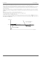
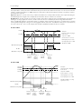
4.5
Alarms Advanced ........................................................................................................................................................................ 30
4.5.1
Behaviour of Alarms after a Power Cycle...................................................................................................................... 30
4.5.2
Example 1 .......................................................................................................................................................................... 30
4.5.3
Example 2 .......................................................................................................................................................................... 30
4.5.4
Example 3 .......................................................................................................................................................................... 30
4.5.5
Diagnostic Alarms ............................................................................................................................................................ 31
4.5.6
Out of Range Indication .................................................................................................................................................. 31
4.6
Other Levels of Operation......................................................................................................................................................... 32
4.7
Level 2 Operation ....................................................................................................................................................................... 32
4.7.1
To Select Level 2 ............................................................................................................................................................... 32
4.7.2
Operator Level 2 Parameters.......................................................................................................................................... 33
4.8
User Calibration .......................................................................................................................................................................... 36
4.9
To Return to Level 1 ................................................................................................................................................................... 36
4.10
Auto, Manual and Off Mode ..................................................................................................................................................... 37
4.10.1
To Select Auto, Manual or Off Mode............................................................................................................................. 37
4.11
Estimated Energy Usage ........................................................................................................................................................... 37
4.12
Timer Operation.......................................................................................................................................................................... 38
4.12.1
Dwell Timer........................................................................................................................................................................ 38
4.12.1.1
Example: To Configure and Operate a Dwell Timer........................................................................................ 39
4.12.1.2
Example: To Configure Timer Digital Outputs ................................................................................................. 39
4.12.1.3
Example: To Configure Timer Digital Inputs ..................................................................................................... 39
4.12.2
Delayed Switch on Timer ................................................................................................................................................ 40
4.12.2.1
Example: To Configure and Set up a Delayed Switch on Timer .................................................................... 40
4.12.3
Soft Start Timer ................................................................................................................................................................. 41
4.12.3.1
Example: To Configure and Set up a Soft Start Timer ..................................................................................... 41
5.
Configuration Level .............................................................................................................................................. 42
5.1
5.2
2
To Select Configuration Level .................................................................................................................................................. 42
Configuration Level Parameters .............................................................................................................................................. 43
5.2.1
Summary of ‘P’ Codes ...................................................................................................................................................... 43
5.2.2
Analogue Input ................................................................................................................................................................. 44
5.2.3
Input Ranges and Limits .................................................................................................................................................. 45
5.2.4
Control ............................................................................................................................................................................... 46
5.2.5
Output 1 ............................................................................................................................................................................. 47
5.2.6
Output 2 ............................................................................................................................................................................. 48
5.2.7
Output 3 ............................................................................................................................................................................. 49
5.2.8
Output 4 ............................................................................................................................................................................. 50
5.2.9
DC Output Range ............................................................................................................................................................. 50
5.2.10
Setpoint Retransmission Range...................................................................................................................................... 50
5.2.11
Alarms................................................................................................................................................................................. 51
5.2.12
Current Transformer ........................................................................................................................................................ 52
5.2.13
Loop Break Alarm ............................................................................................................................................................. 52
5.2.14
Sensor Break, Loop Break and Current (CT) Alarms................................................................................................... 53
5.2.14.1
Sensor Break Impedance ..................................................................................................................................... 53
5.2.15
Timer................................................................................................................................................................................... 54
5.2.16
Digital (Contact) Inputs .................................................................................................................................................... 55
5.2.17
Digital Communications .................................................................................................................................................. 56
5.2.17.1
Broadcast Communications ................................................................................................................................. 57
5.2.18
Pushbutton Functionality................................................................................................................................................. 58
5.2.19
Display Functionality ........................................................................................................................................................ 59
5.2.20
Passcodes .......................................................................................................................................................................... 59
5.2.21
Energy Meter Source ....................................................................................................................................................... 60
5.2.22
Recovery Point .................................................................................................................................................................. 61
5.2.22.1
Recovery Point Save .............................................................................................................................................. 61
5.2.22.2
Recovery Point Load .............................................................................................................................................. 61
Part No HA031260 Issue 1
May -12
Piccolo Range
6.
User Manual
Controller Block Diagram..................................................................................................................................... 62
6.1
7.
Input/Output ................................................................................................................................................................................ 63
Control.................................................................................................................................................................... 64
7.1
Types of Control .......................................................................................................................................................................... 64
7.1.1
On/Off Control .................................................................................................................................................................. 64
7.1.2
PID Control ........................................................................................................................................................................ 64
7.1.3
Proportional Band ‘PB’.................................................................................................................................................... 65
7.1.4
Integral Term ‘Ti’ ............................................................................................................................................................ 65
7.1.5
Derivative Term ‘TD’ ........................................................................................................................................................ 66
7.1.6
Cooling Algorithm ............................................................................................................................................................ 66
7.1.7
Relative Secondary (Cool) Gain ‘r2G’ .......................................................................................................................... 66
7.1.8
High and Low Cutback ‘Cb.Hi’ and ‘Cb.Lo’ ................................................................................................................ 67
7.1.9
Manual Reset ‘Nr’ ............................................................................................................................................................ 67
7.1.10
Loop Break......................................................................................................................................................................... 68
7.2
Tuning ........................................................................................................................................................................................... 69
7.2.1
Loop Response ................................................................................................................................................................. 69
7.2.2
Initial Settings .................................................................................................................................................................... 70
7.2.3
Automatic Tuning ............................................................................................................................................................. 71
7.2.4
To Start Auto Tune ............................................................................................................................................................ 71
7.2.5
Auto Tune from Below SP – Heat/Cool .......................................................................................................................... 72
7.2.6
Auto Tune From Below SP – Heat Only ......................................................................................................................... 73
7.2.7
Auto Tune at Setpoint – Heat/Cool ................................................................................................................................ 74
7.2.8
Manual Tuning................................................................................................................................................................... 75
7.2.9
Manually Setting Relative Cool Gain ............................................................................................................................. 75
7.2.10
Manually Setting the Cutback Values ............................................................................................................................ 76
7.2.11
Effect of Control Action, Hysteresis and Deadband ................................................................................................... 77
8.
Digital Communications ....................................................................................................................................... 78
8.1
8.2
8.3
8.4
8.5
Configuration Port ...................................................................................................................................................................... 78
EIA485 Field Communications Port ........................................................................................................................................ 78
Master/Slave (Broadcast) Communications ........................................................................................................................... 79
EEPROM Write Cycles ................................................................................................................................................................ 80
Broadcast Master Communications Connections ................................................................................................................. 81
8.5.1
Wiring ................................................................................................................................................................................. 81
8.6
DATA ENCODING....................................................................................................................................................................... 81
8.7
Parameter Modbus Addresses ................................................................................................................................................. 82
9.
Calibration ............................................................................................................................................................. 86
9.1
To Check Input Calibration........................................................................................................................................................ 86
9.1.1
Precautions ........................................................................................................................................................................ 86
9.1.2
To Check mV Input Calibration ...................................................................................................................................... 86
9.1.3
To Check Thermocouple Input Calibration .................................................................................................................. 87
9.1.4
To Check RTD Input Calibration ..................................................................................................................................... 87
9.2
Input Calibration ......................................................................................................................................................................... 88
9.2.1
To Calibrate mV Input ...................................................................................................................................................... 88
9.2.2
To Calibrate Thermocouple Input.................................................................................................................................. 89
9.2.3
To Calibrate RTD Input .................................................................................................................................................... 90
9.2.4
To Calibrate mA Outputs ................................................................................................................................................ 91
9.2.5
CT Calibration ................................................................................................................................................................... 92
9.2.6
To Return to Factory Calibration .................................................................................................................................... 93
9.3
Calibration Parameters .............................................................................................................................................................. 93
10.
Configuration Using iTools .................................................................................................................................. 94
10.1
Loading an IDM ........................................................................................................................................................................... 94
10.1.1
Using the H Communications Port ................................................................................................................................. 94
10.2
Connecting a PC to the Controller ........................................................................................................................................... 94
10.2.1
Configuration Clip ............................................................................................................................................................ 94
10.3
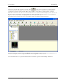
Starting iTools .............................................................................................................................................................................. 95
10.4
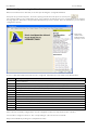
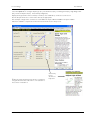
Configuration using the Wizard ............................................................................................................................................... 96
10.4.1
Sensor Input....................................................................................................................................................................... 97
10.4.2
Setpoints ............................................................................................................................................................................ 98
10.4.3
Control ................................................................................................................................................................................ 98
10.4.4
Alarms ................................................................................................................................................................................. 99
10.4.5
Timer ................................................................................................................................................................................... 99
10.4.5.1
Dwell Timer ............................................................................................................................................................. 99
10.4.5.2
Delay Timer ............................................................................................................................................................. 100
10.4.5.3
Soft Start Timer ....................................................................................................................................................... 100
10.4.6
Outputs............................................................................................................................................................................... 101
10.4.7
Digital Inputs ..................................................................................................................................................................... 101
10.4.8
Current Transformer Input .............................................................................................................................................. 102
Part No HA031260
Issue 1 May-12
3
User Manual
Piccolo Range
10.4.9
Energy ................................................................................................................................................................................ 102
10.4.10
Digital Communications .................................................................................................................................................. 103
10.4.11
Pushbutton and Display Functionality........................................................................................................................... 103
10.4.12
Promote.............................................................................................................................................................................. 104
10.4.13
Example 4: Summary ...................................................................................................................................................... 104
10.5
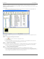
The ‘Browse’ List ......................................................................................................................................................................... 105
10.5.1
Operating List.................................................................................................................................................................... 105
10.5.1.1
Settings .................................................................................................................................................................... 105
10.5.1.2
Variables .................................................................................................................................................................. 106
10.5.1.3
Status ....................................................................................................................................................................... 106
10.5.1.4
User Calibration ..................................................................................................................................................... 106
10.5.2
Configuration List ............................................................................................................................................................. 107
10.5.2.1
Example: To Configure the Sensor Input.......................................................................................................... 107
10.5.2.2
Example: To Configure Outputs for Control .................................................................................................... 108
10.5.2.3
Example: To Configure Alarms........................................................................................................................... 109
10.5.2.4
Example: To Store and Retrieve Current Settings in the Controller ............................................................. 110
10.5.2.5
To Load Stored Settings in the Controller ......................................................................................................... 110
10.5.2.6
To Return to Factory Settings............................................................................................................................... 110
10.5.2.7
To Return to Quick Start Configuration .............................................................................................................. 110
10.5.3
Summary. ........................................................................................................................................................................... 111
10.6
Configurations only available using iTools ............................................................................................................................ 112
10.6.1
Example: To Promote Parameters ................................................................................................................................ 112
10.6.2
To Load A Special Linearisation Table .......................................................................................................................... 113
10.7
Cloning ......................................................................................................................................................................................... 114
10.7.1
Save to File......................................................................................................................................................................... 114
10.7.2
To Clone a New Controller ............................................................................................................................................. 114
10.7.3
Clone Error ........................................................................................................................................................................ 114
11.
Appendix A Factory Default Settings ............................................................................................................... 115
11.1
11.2
12.
13.
Factory Default Configuration .................................................................................................................................................. 115
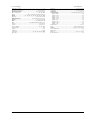
Factory Default Parameter Settings ........................................................................................................................................ 115
Appendix B TECHNICAL SPECIFICATION ....................................................................................................... 116
Index ....................................................................................................................................................................... 118
Issue Status of this Manual
Issue 1 of this Manual applies to software versions V1.01.
4
Part No HA031260 Issue 1
May -12
Piccolo Range
User Manual
1.
Installation and Basic Operation
1.1
What Instrument Do I Have?
Thank you for choosing this Controller.
It provides precise control of industrial processes and is available in three standard DIN sizes:•
1/16 DIN Model Number P116
•
1/8 DIN Model Number P108
•
1/4 DIN Model Number P104
A universal input accepts various thermocouples, RTDs or process inputs. Up to three (P116) or four (P108 and
P104) outputs can be configured for control, alarm or re-transmission purposes. Digital communications and a
current transformer input are available as options.
The controller may be ordered against a hardware ordering code only (section 1.5.1). In this case when it is new
and first switched on ‘out of the box’ it will start in a ‘Quick Configuration’ mode (section 4.1). Alternatively, it may
be ordered against both hardware and software codes, in which case it will be supplied configured and will start up
directly showing the operator display (section 4.2). A label fitted to the right side of the sleeve shows this ordering
code together with the serial number, which also includes the date of manufacture. A label on the left side shows
the terminal connections for the hardware fitted.
A full configuration mode may also be entered and provides more detailed functionality to be configured (section
5).
This Manual takes you through all aspects of installation, wiring, configuration and use of the controller.
1.2
Unpacking Your Controller
The controller is supplied with:•
Sleeve (with the controller fitted in the sleeve)
•
Two panel retaining clips and IP65 sealing gasket mounted on the sleeve
•
Component packet containing a snubber for a relay output (see section 2.10) and a 2.49Ω resistor for a current
input (see section 2.5)
•
Installation sheet Part Number HA031173EFG (English, French, German) and HA031173ISC (Italian, Spanish,
Chinese).
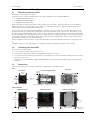
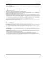
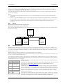
1.3
Dimensions
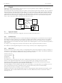
General views of the controllers are shown below together with overall dimensions.
P116
Front View
1.25mm
(0.5in)
48mm
(1.89in)
48mm
(1.89in)
Side View (Right Side)
Top View
90mm (3.54in)
Latching
ears
IP65 Sealing Gasket
Panel retaining clips
Panel retaining clip
P108 and P104
P108 Front View
P104 Front View
Side View (Left Side)
Latching
ears
96mm
(3.78in)
Latching
ears
48mm
(1.89in)
Part No HA031260
96mm (3.78in)
Issue 1 May-12
90mm (3.54in)
IP65 Sealing
Gasket
5
User Manual
1.4
Piccolo Range
Step 1: Installation
This instrument is intended for permanent installation, for indoor use only, and enclosed in an electrical panel
o
o
Select a location which is subject to minimum vibrations the ambient temperature is within 0 and 55 C (32 - 131 F)
and humidity 5 to 95% RH non condensing.
The instrument can be mounted on a panel up to 15mm thick.
To ensure IP65 front protection, mount on a non-textured surface.
Please read the safety information in section 3 before proceeding. An EMC Booklet, part number HA025464, gives
further installation information and can be downloaded from www.eurotherm.co.uk.
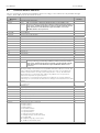
1.4.1
Panel Mounting the Controller
1.
Prepare a cut-out in the mounting panel to the size shown. If a number of controllers are to be mounted in the
same panel observe the minimum spacing shown.
2.
Carefully remove the panel retaining clips from the sleeve using figures or a small screwdriver.
3.
To achieve IP65 sealing, make sure the gasket is fitted behind the front bezel of the controller
4.
Insert the controller through the cut-out
5.
Spring the panel retaining clips back into place. Secure the controller in position by holding it level and
pushing both retaining clips forward.
6.
Peel off the protective cover from the display.
7.
If the panel retaining clips subsequently need removing, they can be unhooked from the side with either your
fingers or a screwdriver.
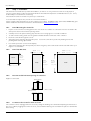
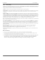
1.4.2
Panel Cut Out Sizes
92 mm - 0.0 + 0.8
3.62 in -0.00, +0.03
45 mm - 0.0 + 0.6
1.77 in -0.00, +0.02
45 mm
- 0.0 + 0.6
P116
1.77 in
-0.00, +0.02
P108
45 mm - 0.0 + 0.6
1.77 in -0.00, +0.02
1.4.3
92 mm
- 0.0 + 0.8
- 0.0 + 0.8
3.62 in
3.62 in
-0.00, +0.03
-0.00, +0.03
P104
Recommended minimum spacing of controllers
Applies to all models.
10mm (0.4 in)
38mm (1.5 in)
1.4.4
92 mm
(Not to scale)
To Remove the Controller from its Sleeve
The controller can be unplugged from its sleeve by easing the latching ears outwards and pulling it forward out of
the sleeve. When plugging it back into its sleeve, ensure that the latching ears click back into place to maintain the
IP65 sealing.
6
Part No HA031260 Issue 1
May -12
Piccolo Range
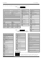
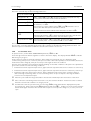
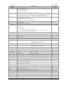
1.5
1.5.1
User Manual
Order Code
Hardware
1
2
3
4
5
Model
Function Supply OP1/2/3 OP4
Voltage
6
7
Options Label
8
9
10
Special
Warranty Certificates Accessories Preconfiguration
1. Model No.
7. Custom Label
P116
P108
P104
XXXXXX
1/16 DIN size
1/8 DIN size
1/4 DIN size
11
12
None
8. Special
2. Function
XXXXXX
CC
CP
9. Warranty
Controller
Controller/Programmer
XXXXX
WL005
3. Supply Voltage
VH
VL
LRX
RRX
RCX
LTX
Standard
Extended
10. Certificates
100–230Vac
24Vac/dc
4. Outputs (OP1, OP2)
No special required
P116
OP1 Logic, OP2 Relay
OP1 Relay, OP2 Relay
OP1 Relay, OP2 Analogue isolated
OP1 Logic, OP2 Triac
(not supported for supply voltage VL)
XXXXX
CERT1
CERT2
None
Certificate of conformity
5 Point Factory Calibration
11. Accessories
XXXXXX
RES250
RES500
None
250R resistor for 0-5Vdc OP
500R resistor for 0-10Vdc OP
4. Outputs (OP1, OP2, OP3) P108 and 104
12. Pre-configuration
LRR
RRR
RRC
0
F
P
LTR
OP1 Logic, OP2 Relay, OP3 Relay
OP1 Relay, OP2 Relay, OP3 Relay
OP1 Relay, OP2 Relay, OP3 Analogue
isolated
OP1 Logic, OP2 Triac, OP3 Relay
(not supported for supply voltage VL)
Notes regarding Pre-configuration
0
5. Output 4 (OP4)
X
R
Disabled
Changeover Relay
6. Options
XXX
XCL
4CL
Part No HA031260
F
P
None
CT & Digital input 1
EIA485 + CT & Digital input 1
Issue 1 May-12
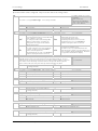
Quick code entry requested at first start up
Factory default table loaded
Quick code pre-loaded
The controller will start up showing the
request of SET1 followed by SET2. The
values of SET1 and SET2 must be entered by
the user when the controller is first powered
up. See section 4.1.3.
Controller will start in operating mode with a
predetermined set of parameters.
See section 11.
The controller will start up with a preloaded
set of characters as specified by the
Configuration Code as defined in the next
section.
7
User Manual
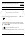
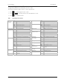
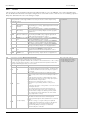
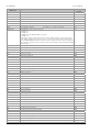
1.5.2
Piccolo Range
Configuration Code
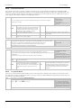
The controller can be ordered and supplied pre-configured and is shown by the code below.
(Note: These codes also correspond with the Quick Codes listed in section 4.1.3. where SET1 corresponds to tables
1, 2, 3 and 4 and SET2 corresponds to tables 5, 6, 7 and 8).
1
2
3
4
5
6
7
8
Input Type
Range
Output 1
Output 2
Output 3
Output 4
Digital Input 1
Digital Input 2
1. Input Type
Thermocouple
X
No input type specified
B
Type B
J
H
L
N
R
S
T
C
PID heating - logic, relay
PID cooling - logic, relay
ON/OFF heating - logic, relay
ON/OFF cooling - logic, relay
Resistance Thermometer
P
Pt100
Alarm 3
0
1
2
3
4
Energised in alarm
High alarm
Low alarm
Deviation high
Deviation low
Deviation band
Linear
V
0-80mV
2
0-20mA
4
4-20mA
Event (1)
E
R
Note (1)
Timer/programmer events
Timer end status
Timer run status
If the timer is configured as a Dwell Timer
2. Range
X
No range specified
5. Output 2
O
C Full Range
O
F Full Range
Celsius
0
0-100
1
0-200
2
0-400
3
0-600
4
0-800
5
0-1000
6
0-1200
7
0-1400
8
0-1600
9
0-1800
8
Control
H
C
J
F
C
F
Type J
Type K
Type L
Type N
Type R
Type S
Type T
Custom/Type C
3. Output 1
X
No output specified
N
Unconfigured
Fahrenheit
G
32-212
H
32-392
I
32-752
J
32-1112
L
32-1472
M
32-1832
N
32-2192
P
32-2552
R
32-2912
T
32-3272
De-energised in alarm
5
High alarm
6
Low alarm
7
Deviation high
8
Deviation low
9
Deviation band
X
No output specified
N
Unconfigured
Control(2)
H
C
J
F
PID heating - logic, relay or 4- 20 ma (2)
PID cooling - logic, relay or 4- 20 mA (2)
ON/OFF heating - logic, relay or 4- 20 mA (2)
ON/OFF cooling - logic, relay or 4- 20 mA (2)
Alarm 1
0
1
2
3
4
Energised in alarm
High alarm
Low alarm
Deviation high
Deviation low
Deviation band
DC OUT
T
U
Y
A
B
D
Retransmission
4 -20mA Set Point
4 -20mA Process Value
4 -20mA Output power
0 -20mA Set Point
0 -20mA Process Value
0 -20mA Output power
Event (1)
E
R
Note (1)
Note (2)
Timer/programmer events
Timer end status
Timer run status
If the timer is configured as a Dwell Timer
Output 2 can be DC linear on P116 only
De-energised in alarm
5
High alarm
6
Low alarm
7
Deviation high
8
Deviation low
9
Deviation band
Part No HA031260 Issue 1
May -12
Piccolo Range
User Manual
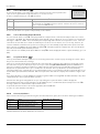
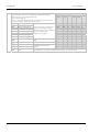
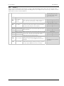
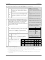
Configuration (Continued)
1
2
3
4
5
6
7
8
Input Type
Range
Output 1
Output 2
Output 3
Output 4
Digital Input 1
Digital Input 2
5. Output 3 (Only available in P108 and P104)
X
No output specified
N
Unconfigured
Control
H
C
J
F
PID heating - relay or 4- 20 mA
PID cooling - relay or 4- 20 mA
ON/OFF heating - relay or 4- 20 mA
ON/OFF cooling - relay or 4- 20 mA
Alarm 3
0
1
2
3
4
DC OUT
T
U
Y
A
B
D
Energised in alarm
De-energised in alarm
High alarm
5
High alarm
Low alarm
6
Low alarm
Deviation high
7
Deviation high
Deviation low
8
Deviation low
Deviation band
9
Deviation band
Retransmission
4 -20mA Set Point
4 -20mA Process Value
4 -20mA Output power
0 -20mA Set Point
0 -20mA Process Value
0 -20mA Output power
Event (1)
E
R
Note (1)
Timer/programmer events
Timer end status
Timer run status
If the timer is configured as a Dwell Timer
7. Digital Input 1
X
Digital Input not specified
N
Unconfigured
A
Alarm acknowledge
S
Setpoint 2 select
L
Keylock
T
Timer reset
R
Timer run
U
Timer run/reset
H
Timer hold
M
Manual status
B
Standby mode
8. Digital Input 2
X
Digital Input not specified
N
A
S
L
T
R
U
H
M
B
Unconfigured
Alarm acknowledge
Setpoint 2 select
Keylock
Timer reset
Timer run
Timer run/reset
Timer hold
Manual status
Standby mode
6. Output 4
X
No output specified
N
Unconfigured
Control
H
C
J
F
PID heating - relay
PID cooling - relay
ON/OFF heating - relay
ON/OFF cooling - relay
Alarm 2
0
1
2
3
4
Energised in alarm
High alarm
Low alarm
Deviation high
Deviation low
Deviation band
Event (1)
E
R
Note (1)
Timer events
Timer end status
Timer run status
If the timer is configured as a Dwell Timer
Part No HA031260
De-energised in alarm
5
High alarm
6
Low alarm
7
Deviation high
8
Deviation low
9
Deviation band
Issue 1 May-12
9
User Manual
Piccolo Range
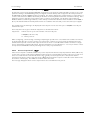
2.
Step 2: Wiring
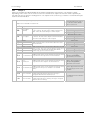
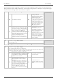
2.1
Terminal Layout P116 Controller
!
Ensure that you have the correct supply for your controller
Check order code of the controller supplied
+
OP1
NO
1A
-
C
+
NO
OP2
-
C
1B
2A
DI1
2B
High Voltage
Power Supply
L
N
100 – 230Vac +15%
AA
NO
C
AB
C
LA
AC
NC
COM
HD
VI
A(+)
B(-)
HE
V+
+
+
+
+
10V
Input
2.49
HF
V-
mA
-
Sensor
input
-
mV
10V Potential divider
module
Part No SUB21/IV10
24
24Vac/dc
Polarity not important
24
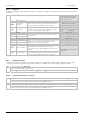
Terminal Layout P108 and P104 Controllers
NO
+
OP1
-
C
NO
C
LB
HE
A(+)
LC
HF
B(-)
3A
CT
3B
C
+
3C
LA
-
3D
VI
L
V+
N
V-
NO
C
High Voltage
Power Supply
100 – 230Vac +15%
OP4 Changeover relay output
NC
COM
-
24Vac/dc
Polarity not important
AB
HD
+
Low Voltage
Power Supply
1B
NO
2B
Digital
(Contact)
input DI2
24V Transmitter
power supply
AA
AC
C
OP3
1A
2A
OP2
EIA485 digital
communications
CT input
Digital (Contact) input DI1
+
+
+
+
2.49
-
mA
24
mV
10V
Input
Sensor
input
10V Potential divider
module
Part No SUB21/IV10
24
Key to symbols used in wiring diagrams
Logic (SSR drive) output
10
OP4 Changeover relay output
Digital
Communications
EIA485
Low Voltage
Power Supply
2.2
CT
CT
Relay output
0-20 or 4-20mA analogue output isolated
Triac output
Current transformer input
Contact input
Changeover relay output
Part No HA031260 Issue 1
May -12
Piccolo Range
User Manual
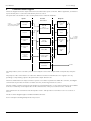
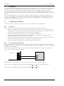
Isolation Boundaries
100-230V
or 24V
DI1/DI2
24Vdc
All outputs (except
OP1 Logic), are
isolated 300Vac
μP
Output 1 Logic is
not isolated from
the sensor input
EIA485
CT
OP1
OP2 - 4
IP1
Digital Inputs DI1 and
DI2 are not isolated
from the CT or sensor
input, IP1.
300Vac
2.3
Wire Sizes
The screw terminals accept wire sizes from 0.5 to 1.5 mm (16 to 22AWG). Hinged covers prevent hands or metal
making accidental contact with live wires. The rear terminal screws should be tightened to 0.4Nm (3.5lb in).
2.4
Controller Power Supply
1.
Before connecting the instrument to the power line, make sure that the line voltage corresponds to the
description on the identification label.
2.
Use copper conductors only.
3.
For 24V the polarity is not important
4.
The power supply input is not fuse protected. This should be provided externally
Recommended external fuse ratings are as follows:For 24 V ac/dc, fuse type: T rated 2A 250V
For 100-230Vac, fuse type: T rated 2A 250V.
2.4.1
High Voltage Power Supply
L
Line
• 100 to 230Vac, +15%, 48 to 62 Hz
N
Neutral
• Power rating P116: 6W; P108 and P104: max 8W
2.4.2
Low Voltage Power Supply
• 24Vac, -15%, +10%
24
24V
24
24V
• 24Vdc, -15%, +20% + 5% ripple voltage
• Power rating P116: 6W; P108 and P104: max 8W
Part No HA031260
Issue 1 May-12
11
User Manual
2.5
Piccolo Range
Sensor Input (Measuring Input)
Precautions
• Do not run input wires together with power cables
• When shielded cable is used, it should be grounded at one point only
• Any external components (such as zener barriers, etc) connected between sensor and input terminals may cause
errors in measurement due to excessive and/or un-balanced line resistance or possible leakage currents
• The sensor input is not isolated from the logic outputs & digital inputs
• Pay attention to line resistance; a high line resistance may cause measurement errors
• A single sensor should not be connected to more than one instrument. Sensor break operation could be
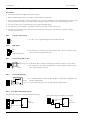
severely compromised
2.5.1
Thermocouple Input
+
V+
V-
• Use the correct compensating cable preferably shielded
-
2.5.2
RTD Input
VI
PRT
V+
PRT
V-
Lead compensation
2.5.3
• The resistance of the three wires must be the same. The line resistance may
cause errors if it is greater than 22Ω
Linear Input (mA or mV)
+
V+
+
mA/mV input
-
R
V-
-
• For a mA input connect the 2.49Ω burden resistor (R) supplied between the +
and - input terminals as shown
Shield
2.5.4
• If shielded cable is used it should be grounded in one place only as shown
Linear Input (Volts)
+
V+
+
V-
-
2.5.5
100KΩ
806Ω
0-10V
Input
• For a 0-10Vdc input an external input adapter is required (not supplied). Part
number: SUB21/IV10
• Sensor break alarm does not operate with this adaptor fitted.
Two-Wire Transmitter Inputs
Using internal 24V power supply (P108 and P104 only)
V+
V3C
3D
12
+
+
-
V+
2-Wire
Transmitter
2.49Ω
+
All models using an external power supply
V-
+
-
2.49Ω
-
2-Wire
Transmitter
+
+
External
power
Part No HA031260 Issue 1
May -12
Piccolo Range
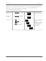
2.6
User Manual
Output 1
This output is available in all models and can be logic (SSR drive), or relay, depending on the order code.
For output functions, see Quick Start Code in section 4.1.1 or ‘P’ Codes in section 5.2.
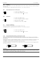
2.6.1
2.6.2
Relay Output (Form A, normally open)
1A
• Isolated output 300Vac CAT II
1B
• Contact rating: 2A 230Vac +15% resistive
Logic (SSR drive) Output
1A
1B
• Isolated output 300Vac CAT II
+
• Output ON state: 12Vdc at 40mA max
-
• Output OFF state: <300mV, <100μA
• The output switching rate must be set to prevent damage to the output device
in use. See parameter 1.PLS in section 4.7.2.
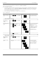
2.7
Output 2
Output 2 is available in all models.
In P116 it can be ordered as Relay, Analogue or Triac.
In P108 and P104 it can be ordered as Relay or Triac.
For output functions, see Quick Start Code in section 4.1.1 or ‘P’ Codes in section 5.2.
2.7.1
2.7.2
Relay Output (Form A, normally open)
2A
• Isolated output 300Vac CAT II
2B
• Contact rating: 2A 230Vac +15% resistive
DC Output (P116 only)
2A
2B
• Output isolated 300Vac
+
• Software configurable: 0-20mA or 4-20mA.
-
• Max load resistance: 500Ω
• Calibration accuracy: +(<1% of reading + <100μA)
2.7.3
Triac Output
2A
• Isolated output 300Vac CATII
2B
• Rating: 0.75A rms, 30Vac (minimum) to 230Vac +15% resistive
Part No HA031260
Issue 1 May-12
13
User Manual
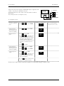
2.8
Piccolo Range
Output 3
Output 3 is only available in the models P108 and P104. It will be either a Relay or Analogue output depending on
the order code.
For output functions, see Quick Start Code in section 4.1.1. or ‘P’ codes in section 5.2.
2.8.1
Relay Output (Form A, normally open)
3A
• Isolated output 300Vac CAT II
3B
• Contact rating: 2A 230Vac +15% resistive
2.8.2
DC Output
• Isolated output 300Vac CAT II
3A
3B
+
• Software configurable: 0-20mA or 4-20mA
-
• Max load resistance: 500Ω
• Calibration accuracy: 0.5%, +100μA
2.9
Output 4 (AA Relay)
Output 4 is a changeover relay (Form C) and is available in all models.
For output functions, see Quick Start Code in section 4.1.1 or ‘P’ Codes in section 5.2.
AA
• Isolated output 300Vac CAT II
AB
• Contact rating: 2A 230Vac +15% resistive
AC
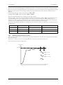
2.10
General Note About Relays and Inductive Loads
High voltage transients may occur when switching inductive loads such as some contactors or solenoid valves.
Through the internal contacts, these transients may introduce disturbances which could affect the performance of
the instrument.
For this type of load it is recommended that a ‘snubber’ is connected across the normally open contact of the relay
switching the load. The snubber recommended consists of a series connected resistor/capacitor (typically
15nF/100Ω). A snubber will also prolong the life of the relay contacts.
A snubber should also be connected across the output terminal of a triac output to prevent false triggering under
line transient conditions.
2A
2B
C
2A
2B
C
WARNING
When the relay contact is open or it is connected to a high impedance load, the snubber passes a current (typically
0.6mA at 100Vac and 1.2mA at 230Vac). You must ensure that this current will not hold on low power electrical
loads. If the load is of this type the snubber should not be connected.
14
Part No HA031260 Issue 1
May -12
Piccolo Range
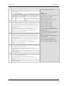
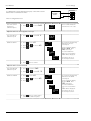
2.11
User Manual
Digital Inputs DI1 & DI2
Digital input 1 is an optional input in all P100 series controllers.
Digital input 2 is always fitted in models P108, and P104, but is not available in P116.
Digital in 1
Digital in 2
• Not isolated from the current transformer input or the sensor input
C
LB
• Switching: 12Vdc at 40mA max
LA
LC
• Contact open > 500Ω. Contact closed < 200Ω
• Input functions: Please refer to the list in the quick codes, section 4.1.3.
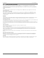
2.12
Current Transformer
The current transformer input is an optional input in all P100 series controllers.
• C terminal is common to both the CT input and Digital input A. They are,
CT
therefore, not isolated from each other or the PV input.
C
• CT input current: 0-50mA rms (sine wave, calibrated) 50/60Hz
• A burden resistor, value 10Ω, is fitted inside the controller.
• It is recommended that the current transformer is fitted with a voltage limiting
device to prevent high voltage transients if the controller is unplugged. For
example, two back to back zener diodes. The zener voltage should be
between 3 and 10V, rated at 50mA.
• CT input resolution: 0.1A for scale up to 10A, 1A for scale 11 to 100A
• CT input accuracy: +4% of reading.
2.13
Transmitter Power Supply
The Transmitter Supply is not available in the Model P116.
It is fitted as standard in the Models P108 and P104.
3C
3D
+
24Vdc
-
Part No HA031260
• Isolated output 300Vac CAT II
• Output: 24Vdc, +/- 10%. 28mA max.
Issue 1 May-12
15
User Manual
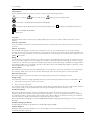
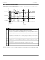
2.14
Piccolo Range
Digital Communications
Optional.
Digital communications uses the Modbus protocol EIA485 2-wire (formerly RS485).
☺ Cable screen should be grounded at one point only to prevent earth loops.
•
Isolated 300Vac CAT II.
EIA485 Connections
220Ω
termination
resistor
Twisted pair
Tx
Rx
Tx
Com
RxB
TxB
RxA
TxA
Com Com
Rx
HD
Common
HE
A(+)
HF
B(-)
Screen
EIA232/EIA485 2wire communications
converter Type
KD485 is
recommended to
convert EIA485 to
the EIA232 port on
the PC
HD
HE
HF
Daisy Chain
to further
controllers
220Ω termination
resistor on last
controller in the line
16
Part No HA031260 Issue 1
May -12
Piccolo Range
User Manual
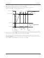
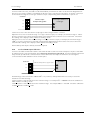
2.15
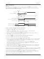
Wiring Examples
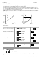
2.15.1
Heat/Cool Controller
This example shows a heat/cool temperature controller where the heater control uses a SSR, triggered by a logic
output on OP1, and the cooling control uses the relay, OP4.
*
L
Heater fuse
Controller fuse
CT
AA
C
AB
LA
AC
2B
COM HD
VI
L
A(+) HE
V+
N
B(-) HF
V-
1A
Solid State
Relay
1B
(e.g. TE10)
2A
Heater
Relay output fuse
CT
DI1
Snubber, section 2.10
Cooling or
alarm relay
+
- T/C
N
*
Safety requirements for permanently connected equipment state:
•
A switch or circuit breaker shall be included in the building installation
•
It shall be in close proximity to the equipment and within easy reach of the operator
•
It shall be marked as the disconnecting device for the equipment
☺
A single switch or circuit breaker can drive more than one instrument
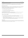
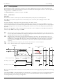
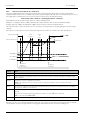
2.15.2
CT Wiring Diagram
This diagram shows an example of wiring for a CT input.
Heater
fuse
L
Current
Transformer
Solid State
Relay
Heater
N
(e.g. TE10)
Thermocouple
CT
AA
C
AB
LA
AC
2B
COM HD
VI
L
A(+) HE
V+
N
B(-) HF
V-
1A
1B
Controller
fuse
L
N
2A
DI1
+
-
Note: a burden resistor value 10Ω is mounted inside the
controller.
To prevent a build up of high voltages at the output of the CT
if it is disconnected from the controller, it is recommended
that a voltage limiting device be connected directly across the
output of the CT. A suitable device is two back to back zener
diodes, rated between 3 and 10V at 50mA, as shown.
Part No HA031260
Issue 1 May-12
Current transformer CT
17
User Manual
3.
Piccolo Range
Safety and EMC Information
This controller is intended for industrial temperature and process control applications when it will meet the
requirements of the European Directives on Safety and EMC. Use in other applications, or failure to observe the
installation instructions of this manual may impair safety or EMC. The installer must ensure the safety and EMC of
any particular installation.
Safety
This controller complies with the European Low Voltage Directive 2006/95/EC, by the application of the safety
standard EN 61010.
Electromagnetic compatibility
This controller conforms with the essential protection requirements of the EMC Directive 2004/108/EC, by the
application of a Technical Construction File. This instrument satisfies the general requirements of the industrial
environment defined in EN 61326. For more information on product compliance refer to the Technical
Construction File.
GENERAL
The information contained in this manual is subject to change without notice. While every effort has been made to
ensure the accuracy of the information, your supplier shall not be held liable for errors contained herein.
Unpacking and storage
The packaging should contain an instrument mounted in its sleeve, two mounting brackets for panel installation and
an Installation & Operating guide. Certain ranges are supplied with an input adapter.
If on receipt, the packaging or the instrument are damaged, do not install the product but contact your supplier. If
o
the instrument is to be stored before use, protect from humidity and dust in an ambient temperature range of -30 C
o
to +75 C.
Service and repair
This controller has no user serviceable parts. Contact your supplier for repair.
Caution: Charged capacitors
Before removing an instrument from its sleeve, disconnect the supply and wait at least two minutes to allow
capacitors to discharge. It may be convenient to partially withdraw the instrument from the sleeve, then pause
before completing the removal. In any case, avoid touching the exposed electronics of an instrument when
withdrawing it from the sleeve.
Failure to observe these precautions may cause damage to components of the instrument or some discomfort to
the user.
Electrostatic discharge precautions
When the controller is removed from its sleeve, some of the exposed electronic components are vulnerable to
damage by electrostatic discharge from someone handling the controller. To avoid this, before handling the
unplugged controller discharge yourself to ground.
Cleaning
Do not use water or water based products to clean labels or they will become illegible. Isopropyl alcohol may be
used to clean labels. A mild soap solution may be used to clean other exterior surfaces of the product.
18
Part No HA031260 Issue 1
May -12
Piccolo Range
3.1
User Manual
Installation Safety Requirements
Safety Symbols
Various symbols may be used on the controller. They have the following meaning:
Refer to manual.
Risk of electric shock.
Take precautions against static.
C-tick mark for Australia (ACA) and New Zealand (RSM).
3
Complies with the 40 year Environment Friendly Usage Period.
RoHS
Restriction of Hazardous Substances
Protected by DOUBLE ISOLATION.
☺
Helpful hints
Personnel
Installation must only be carried out by suitably qualified personnel in accordance with the instructions in this
manual.
Enclosure of Live Parts
To prevent hands or metal tools touching parts that may be electrically live, the controller must be enclosed in an
enclosure.
Caution: Live sensors
The controller is designed to operate if the temperature sensor is connected directly to an electrical heating
element. However you must ensure that service personnel do not touch connections to these inputs while they are
live. With a live sensor, all cables, connectors and switches for connecting the sensor must be mains rated for use in
230Vac +15% CATII..
Wiring
It is important to connect the controller in accordance with the wiring data given in this guide. Take particular care
not to connect AC supplies to the low voltage sensor input or other low level inputs and outputs. Only use copper
conductors for connections (except thermocouple inputs) and ensure that the wiring of installations comply with all
local wiring regulations. For example in the UK use the latest version of the IEE wiring regulations, (BS7671). In the
USA use NEC Class 1 wiring methods.
Power Isolation
The installation must include a power isolating switch or circuit breaker. This device should be in close proximity to
the controller, within easy reach of the operator and marked as the disconnecting device for the instrument.
Overcurrent protection
The power supply to the system should be fused appropriately to protect the cabling to the units.
Voltage rating
The maximum continuous voltage applied between any of the following terminals must not exceed 230Vac +15%:
•
relay output to logic, dc or sensor connections;
•
any connection to ground.
The controller must not be wired to a three phase supply with an unearthed star connection. Under fault conditions
such a supply could rise above 264Vac with respect to ground and the product would not be safe.
Conductive pollution
Electrically conductive pollution must be excluded from the cabinet in which the controller is mounted. For
example, carbon dust is a form of electrically conductive pollution. To secure a suitable atmosphere in conditions
of conductive pollution, fit an air filter to the air intake of the cabinet. Where condensation is likely, for example at
low temperatures, include a thermostatically controlled heater in the cabinet.
This product has been designed to conform to BSEN61010 installation category II, pollution degree 2. These are defined
as follows:Installation Category II (CAT II)
The rated impulse voltage for equipment on nominal 230V supply is 2500V.
Pollution Degree 2
Normally only non-conductive pollution occurs. Occasionally, however, a temporary conductivity caused by
condensation shall be expected.
Part No HA031260
Issue 1 May-12
19
User Manual
Piccolo Range
Grounding of the temperature sensor shield
In some installations it is common practice to replace the temperature sensor while the controller is still powered
up. Under these conditions, as additional protection against electric shock, we recommend that the shield of the
temperature sensor is grounded. Do not rely on grounding through the framework of the machine.
Over-temperature protection
When designing any control system it is essential to consider what will happen if any part of the system should fail.
In temperature control applications the primary danger is that the heating will remain constantly on. Apart from
spoiling the product, this could damage any process machinery being controlled, or even cause a fire.
Reasons why the heating might remain constantly on include:
•
the temperature sensor becoming detached from the process
•
thermocouple wiring becoming short circuit;
•
the controller failing with its heating output constantly on
•
an external valve or contactor sticking in the heating condition
•
the controller setpoint is set too high.
Where damage or injury is possible, we recommend fitting a separate over-temperature protection unit, with an
independent temperature sensor, which will isolate the heating circuit.
Please note that the alarm relays within the controller will not give protection under all failure conditions.
Installation requirements for EMC
To ensure compliance with the European EMC directive certain installation precautions are necessary as follows:
•
For general guidance refer to Eurotherm Controls EMC Installation Guide, HA025464.
•
When using relay outputs it may be necessary to fit a filter suitable for suppressing the emissions. The filter
requirements will depend on the type of load.
•
If the unit is used in table top equipment which is plugged into a standard power socket, then it is likely that
compliance to the commercial and light industrial emissions standard is required. In this case to meet the
conducted emissions requirement, a suitable mains filter should be installed.
Routing of wires
To minimise the pick-up of electrical noise, the low voltage DC connections and the sensor input wiring should be
routed away from high-current power cables. Where it is impractical to do this, use shielded cables with the shield
grounded at both ends. In general keep cable lengths to a minimum.
20
Part No HA031260 Issue 1
May -12
Piccolo Range
4.
User Manual
Switch On
Whenever the controller is switched on (powered up) it will start in a diagnostic mode lasting for a few seconds.
The diagnostic display illuminates all bars of each character and every beacon. This is followed by the firmware
version number and the instrument type number as shown below for each model.
P104 Controller
P108 Controller
P116 Controller
≈ 3s
f1.02
P116
≈ 3s
≈ 3s
f1.02
P108
f1.02
P104
The display that automatically follows depends on the way the controller has been supplied or re-configured and is
described in the following sections.
4.1
New Unconfigured Controller
If the controller is supplied new with the Configuration Code = ‘P’ (section 1.5.2) then it is unconfigured and will
start up requesting the ‘Quick Configuration’ codes. This is a built in tool which enables you to quickly configure
commonly used functions such as the input type and range, the outputs and digital input functions.
!
Incorrect configuration can result in damage to the process and/or personal injury and must be carried out
by a competent person authorised to do so. It is the responsibility of the person commissioning the controller to
ensure the configuration is correct.
4.1.1
Quick Configuration Code
The quick configuration code consists of two ‘SETS’ of four characters. The upper section of
the display shows the set selected, the lower section shows the four digits which make up the
set.
s et 1
- - - -
S et 2
- - - -
Adjust these as follows:1.
The first character ‘-‘ will be flashing.
2.
Press
or
3.
Press
accept the change and to scroll to the next character.
☺
☺
You cannot scroll to the next character until the current character is configured.
4.
to enter the required code shown in the quick code tables - section 4.1.3
To return to the first character press
When all four characters have been configured the display will go to Set 2.
no
5.
When the last digit has been entered press
6.
Press
again, the display will show
done
YE S
or
to
done
and
to accept.
The controller will then automatically go to the operator level, section 4.2.
4.1.2
To Load the Factory Default Data
Instead of entering each character individually, it is possible to load the factory default data directly.
See section 11 for the factory default values.
1.
When the SEt1 shows "_ _ _ _"
2.
Press
no
3.
The display will jump to
done
YE S
4.
Press
or
to
done
and
to accept.
The controller will then automatically go to the operator level, section 4.2.
Part No HA031260
Issue 1 May-12
21
User Manual
4.1.3
Piccolo Range
Quick Code Tables
Note: The Quick Code Tables are a repeat of the Order Code tables – section 1.5.2.
Set 1
1
Input Type
1.
2
3
Range
Input Type
4
OP1
OP2
3. Output OP1 – Alarm 3
4. Output OP2 – Alarm 1
n
Unconfigured
n
Unconfigured
b
Thermocouple type B
n
Thermocouple type N
H
PID Heating
H
PID Heating
J
Thermocouple type J
r
Thermocouple type R
C
PID Cooling
J
ON/OFF Heating
H
Thermocouple type K
S
Thermocouple type S
J
ON/OFF Heating
C
PID Cooling
L
Thermocouple type L
t Thermocouple type T
Thermocouple type C or Custom linearisation
F
ON/OFF Cooling
F
ON/OFF Cooling
Thermocouple
C
RTD
Alarm: energised in alarm
Alarm: energised in alarm
0
High alarm
0
High alarm
1
Low alarm
1
Low alarm
mV / mA
2
Deviation high
2
Deviation high
u
0-80mV
3
Deviation low
3
Deviation low
2
0-20mA
4
4-20mA
Deviation band
4
Alarm: de-energised in alarm
Deviation band
4
Alarm: de-energised in alarm
5
High alarm
5
High alarm
6
Low alarm
6
Low alarm
7
Deviation high
7
Deviation high
8
Deviation low
8
Deviation low
9
Deviation band
9
Deviation band
P
2
Platinum resistance thermometer type Pt100
Range
C
o
F
o
C Full range
F Full range
Celsius
Fahrenheit
0
0-100
5
0-1000
G
32-212
N
32-1832
1
0-200
6
0-1200
H
32-392
n
32-2192
2
0-400
7
0-1400
i
32-752
P
32-2552
3
0-600
8
0-1600
J
32-1112
r
32-2912
4
0-800
9
0-1800
L
32-1472
t
32-3272
Event
DC Retransmission (P116)
E
End status
t
4-20mA Setpoint
r
Run status
U
4-20mA PV
y
4-20mA Output
A
0-20mA Setpoint
b
0-20mA PV
0-20mA Output
d
Event
Set 2
5 6 7 8
OP3
OP4 Digital IP1
(not in P116)
E
End status
r
Run status
Digital IP2
(not in P116)
5. Output OP3 – Alarm 3
(only available in P108 and P104)
6. Output OP4 – Alarm 2
7. Digital Input 1
n
Unconfigured
Unconfigured
H
PID Heating
H
A
S
Alarm acknowledge
n
PID Heating
J
ON/OFF Heating
Keylock
C
PID Cooling
C
L
PID Cooling
Timer reset
J
ON/OFF Heating
ON/OFF Cooling
F
Alarm: energised in alarm
T
r
Timer run
U
Timer run/reset
ON/OFF Cooling
F
Alarm: energised in alarm
0
High alarm
H
Timer hold
Manual select
Unconfigured
0
High alarm
1
Low alarm
1
Low alarm
2
Deviation high
2
Deviation high
N
b
3
Deviation low
3
Deviation low
n
Deviation band
4
Alarm: de-energised in alarm
Deviation band
4
Alarm: de-energised in alarm
5
High alarm
5
High alarm
6
Low alarm
6
Low alarm
7
Deviation high
7
Deviation high
8
Deviation low
8
Deviation low
Deviation band
9
Event
Deviation band
9
DC Retransmission
4-20mA Setpoint
t
U
4-20mA PV
y
4-20mA Output
A
0-20mA Setpoint
b
0-20mA PV
Setpoint 2 select
E
End status
r
Run status
Standby mode (outputs off)
8. Digital Input 2 (P108 & P104 only)
A
S
Alarm acknowledge
L
Keylock
T
Timer reset
r
Timer run
U
Timer run/reset
H
Timer hold
N
b
Manual select
n
Unconfigured
Setpoint 2 select
Standby mode (outputs off)
Example
0-20mA Output
d
Event
j C H C
Set 1 - Thermocouple type J, OC, OP1 PID heating, OP2 PID cooling.
E
End status
r
Run status
5 6 a s
Set 2 – OP3 (P108 & P104 only) high alarm, OP4 low alarm, alarm
acknowledge on logic input 1, setpoint select on logic input 2.
22
Part No HA031260 Issue 1
May -12
Piccolo Range
4.1.4
User Manual
Alarm Allocation using the Quick Code
Alarms have a fixed assignment when they are set up by means of the ‘Quick Codes’. The assignment is :OP1 t AL3
OP2 t AL1
OP3 t AL3. If OP1 and OP2 have been allocated to heat/cool then AL3 defaults to Output 3.
OP4 t AL2. If OP1 and OP2 have been allocated to heat/cool then AL2 defaults to Output 4.
In the example shown in the previous section AL2 operates OP4 and AL3 operates AL3, AL1 is not available.
The table below shows some examples of how alarms are allocated for different ‘Quick Codes’:Quick Code
OP1
OP2
OP3
OP4
JCHC 56nn
Heat
Cool
AL3
AL2
JCH5 nnnn
Heat
AL1
No heat/cool
JC56 nnnn
AL3
AL1
AL2 is not used
JCH5 6Cnn
Heat
AL1
AL3
JCH5 6nnn
Heat
AL1
AL3
JCH5 67nn
Heat
AL1
AL3
4.1.5
AL1 is not used
Cool
AL2 is not used
AL2 is not used
AL2
To Re-Enter Quick Code mode
If you need to re-enter the ‘Quick Configuration’ mode it is necessary to do a Cold Start:Warning: A Cold Start will remove all previous configurations. It is recommended that a clone file (section 10.7) is
taken of the controller before attempting a cold start.
To Cold Start the controller refer to section 5.2.22.
4.1.6
Summary of Start-up Displays
In addition to the above mode, the controller may also be ordered with a factory pre-determined set of parameters
loaded as defined by Configuration Order Code F, or with the quick codes pre-loaded as defined by Configuration
Order Code P. A summary of the start up display is shown below for all three modes.
Software Order Code ‘O’.
Software Order Code ‘F’.
≈ 3s
≈ 3s
f1.02
P116
f1.02
P116
Software Order Code ‘P’.
≈ 3s
≈ 3s
s et 1
f1.02
P116
≈ 3s
set1
≈ 3s
J C H C
- - - -
Set2
≈ 3s
n n A S
Quick Codes must be entered
as described in section 4.1.1.
Part No HA031260
Issue 1 May-12
Quick Codes are not requested
or displayed
Quick Codes are briefly
displayed
23
User Manual
4.1.7
Piccolo Range
Subsequent Start-ups
Whenever the controller is powered up it will run through the diagnostic mode. It will then always start in Operator
Level 1 and show the default or ‘HOME’ display – section 4.2.
The start up procedure for an existing controller is slightly different depending how the controller has been
configured.
If the controller has
been configured using
the Quick Configuration
procedure only, section
4.1.1, then the Quick
codes are also
.
displayed for a few
seconds whenever the
controller is switched
on.
4.2
If the factory default
data – section 4.1.2. is
entered OR the
controller is configured
or re-configured using
the ‘P’ codes the quick
codes are not shown
during start up since
they may no longer be
relevant
≈ 3s
f1.02
P116
≈ 3s
set1
≈ 3s
≈ 3s
J C H C
Set2
n n A S
≈ 3s
f1.02
P116
≈ 3s
Front Panel Layout
Measured Temperature
(or Process Value ‘PV’)
Target Temperature *
(Setpoint ‘SP’)
Measured Temperature
(or Process Value ‘PV’)
Target Temperature *
(Setpoint ‘SP’)
Output Power demand *
Operator Buttons
Beacons
ALM
P116 Controller
P108 Controller
P104 Controller
Scroll button. Press to scroll forward through a list of
parameters. Hold down to scroll continuously.
Alarm active (Red)
Lit when output 3 is ON (P108 & P104 only)
Page button. Press to scroll back through a list of parameters.
Hold down to select a different operating level.
This button can be assigned a specific function – see ‘P’ code
P73 section 5.2.18.
Lit when output 4 is ON (typically alarm)
Press to decrease a value.
SPX
Alternative setpoint in use (SP2)
Press to increase a value.
REM
Digital communications active (flashing)
M AN
Manual mode selected
Lit when output 1 is ON (typically heating)
Lit when output 2 is ON (typically cooling )
Press
and
Function key 1
Function key 2
together to return to the operating display.
These buttons are only available in
P108 & P104. For functionality see
section 5.2.18
Alpha-Numeric Display
Top row
* Second Line
* Third Line
24
Measured Temperature (Process Value, PV) or the value of a selected parameter
Target Temperature (Setpoint, SP) or the These are the default parameters. They may be customised to show
mnemonic of a selected parameter
alternative parameters to suit the requirements of a particular
process, see section 5.2.19.
Output power demand
Part No HA031260 Issue 1
May -12
Piccolo Range
4.2.1
User Manual
To Set The Target Temperature (Setpoint ‘SP’).
From the HOME display:Press
to raise the setpoint
Press
to lower the setpoint
The units (if configured *) are displayed briefly when either button is first pressed.
If either button is pressed repeatedly the units are not displayed – it requires about
1 second between button presses for the units to be displayed again.
The new setpoint is entered when the button is released and is indicated by a brief
flash of the display.
* Units are configured in Operator Level 2, section 4.7.2.
4.3
Level 1 Operator Parameters
A minimal list of parameters is available in Operator Level 1 which is designed for day to day use. Access to these
parameters is not protected by a pass code.
Press
to step through the list of available parameters. The mnemonic of the parameter is shown in the lower
display.
The value of the parameter is shown in the upper display. Press
for 30 seconds the controller returns to the HOME display.
or
to adjust this value. If no key is pressed
The parameters that appear depend upon the functions configured. They are:Parameter
Mnemonic
Description and Alterability
Further Information
oP
Auto/Manual/Off mode
Output power.
is described in section
This is read only when the controller is in ‘Auto’ or ‘OFF’ mode and shows the current
output power demand. In a temperature control application, 100% = full heating, -100% 4.10
= full cooling.
When the controller is in ‘Manual’ mode the output power demand can be adjusted using
or
.
SP
Current setpoint.
This is read only when the controller is in ‘Manual’ or ‘OFF’ mode.
Ac.AL
Alarm acknowledge - Yes or no.
This parameter only appears if a latching alarm is configured.
Section 4.4.3
t.St
Status of timer - Run, Reset, Hold, End.
This parameter only appears if the timer function is configured.
Section 4.12 Timer
Operation.
SP1
Setpoint 1 value. Press
or
to raise or lower setpoint 1.
SP2
Setpoint 2 value. Press
or
to raise or lower setpoint 2.
t.eL
Time elapsed. Hours or minutes depending on configuration.
This parameter only appears if the timer function is configured. It is read only.
‘P’ Code P42
t.rE
Time remaining. Hours or minutes depending on configuration.
This parameter only appears if the timer function is configured.
‘P’ Code P42
The time may be extended or reduced when the timer is running by pressing
e.par
e.tot
or
.
Energy counter partial value
This parameter is read only and is intended to measure energy usage for specific batches.
It is also possible to configure the second or third line of the display to read this value
‘P’ Code P74
Energy counter total value
This parameter is read only and is intended to measure energy usage for a complete
process which might consist of a number of batches.
It is also possible to configure the second or third line of the display to read this value
‘P’ Code P75
Note: E.Par and E.tot can be reset using the parameter E.rSt. This is normally available in Operator
Level 2 (section 4.7.2), but it is possible to ‘promote’ it to Level 1 using iTools configuration package.
Alternatively, it is possible to customise pushbuttons F1, F2 or
to display E.rSt.
iTools section 10.5.3.
‘P’ Codes P71, P72 or
P73.
☺
P codes are found in
section 5.2.
Part No HA031260
Issue 1 May-12
25
User Manual
4.4
Piccolo Range
Alarms
Alarms are used to alert an operator when a pre-set level has been exceeded. They are
indicated by flashing the alarm number and the red ALM beacon in the display.
Up to three process alarms may be configured using the Quick Start Codes, section 4.1.1. or
‘P’ Codes P21 to P29.
☺
‘P’ codes are found
in section 5.2.
They may also switch an output, usually a relay, to allow external devices to be operated when an alarm occurs (‘P’
code P11 to P14).
Each alarm can be configured to the types listed below:Alarm Type
Full Scale Low
Full Scale High
Deviation Low
Deviation High
Deviation Band
Description
The alarm is shown if the process value falls below an absolute threshold
The alarm is shown if the process value rises above an absolute threshold
The alarm is shown if the process value deviates below the setpoint by a set threshold
The alarm is shown if the process value deviates above the setpoint by a set threshold
The alarm is shown if the process value deviates above or below the setpoint by a set threshold
In addition to the above alarms the following alarm types may be configured:Sensor Break
If the sensor becomes open circuit the alarm message Sb.r is flashed in the display. The controller
control outputs can be configured to output a ‘safe’ value. ( ‘P’ code P36).
Excess Current
An alarm will be indicated if the current is exceeded. (‘P’ code P33).
Current alarms can be Load, Leakage, Overcurrent
The loop is considered to be broken if the PV does not respond to a change in the output in a given
time. (‘P’ code P34).
Loop Break
If an alarm is not configured it is not shown in the list of level 2 parameters shown in section 4.7.2.
4.4.1
To Set Alarm Setpoints
The levels at which alarms operate are adjusted by the alarm setpoint parameters AL1, AL2 or AL3. By default,
these can only be set in Operator Level 2*, (section 4.7.2). If the controller is configured to measure load
conditions, parameters Ld.AL, LE.AL, Hc.AL are used to set alarm setpoints for load currents.
Press
until the required alarm setpoint is shown *.
Press
or
Press
to accept the value.
to raise or lower the alarm setpoint.
* The alarm setpoint parameters can be ‘promoted’ to Level 1 using iTools (section 10.5.3).
4.4.2
Alarm Indication
ALM
If an alarm occurs, the red
beacon will flash together with the alarm number, for example AL1. If more than
one alarm is present each alarm number is flashed in turn. Any output (usually a relay) attached to an alarm will
operate. An alarm relay can be configured, using the Quick Start Codes or the ‘P’ codes P11 to P14, to be
energised or de-energised in the alarm condition. It is normal to configure the relay to be de-energised in alarm so
that an alarm is indicated if power to the controller fails.
4.4.3
To Acknowledge an Alarm
There are three ways in which an alarm can be acknowledged:
1.
In all cases an alarm can be acknowledged in Level 2, or in Level 1 if it is a latching alarm, as follows:Press
to select Ac.AL (Alarm Acknowledge). This parameter is always present in operator level 2, unless a
function key has been configured for Alarm Acknowledge (‘P’ code P71, P72 or P73).
to select YES.
Press
or
Press
to accept.
2.
By operating an external pushbutton attached to Digital Input 1 or 2, if either of these have been configured for
Alarm Acknowledge (‘P’ code P51 and P52).
3.
Press
or
P72 and P73).
or
if any of these buttons have been configured for Alarm Acknowledge (‘P’ codes P71,
If the alarm is still present the ALM beacon will light continuously and the alarm message will continue to flash.
The action which takes place depends on the latching type of the alarm configured, as described in the next
section.
26
Part No HA031260 Issue 1
May -12
Piccolo Range
4.4.4
User Manual
Alarm Latching
Alarm latching is used to hold the alarm condition active once an alarm has been detected.
Alarm Latching is configured using ‘P’ codes, P22 (Alarm 1), P25 (Alarm 2), P28 (Alarm 3),
P33 (CT Alarm) as:none
Non latching
Auto
Automatic
Nan
Manual
No.AL
No alarm
☺
‘P’ codes are found
in section 5.2.
A non latching alarm will reset itself when the alarm condition is removed.
If it is still present when acknowledged the ALM beacon illuminates constantly, the flashing alarm
messages remain and the output remains active.
An auto latching alarm requires acknowledgement before it is reset. The acknowledgement can
occur BEFORE the condition causing the alarm is removed.
An example of the action for Alarm 1 attached to OP4 is described below:
Alarm 1 occurs
ALM
and AL1 flash.
is ON.
Acknowledge (the alarm is still
ALM
present)
is constant. AL1 remains flashing,
is ON.
Alarm 1 condition is removed.
All conditions are reset.
Alarm 1 occurs
ALM
and AL1 flash.
is ON.
Alarm 1 condition is removed
ALM
and AL1 flash.
is ON.
Acknowledge (the alarm
The alarm indication and output are reset.
condition has been removed)
The alarm continues to be active until both the alarm condition is removed AND the alarm is
acknowledged. The acknowledgement can only occur AFTER the condition causing the alarm is
removed.
An example of the action for Alarm 1 attached to OP4 is described below:
Alarm 1 occurs
ALM
and the alarm number flash.
is ON.
Acknowledge (the alarm is still
The alarm indication and output continue to show alarm.
present)
Alarm 1 condition is removed.
The alarm indication and output continue to show alarm.
Acknowledge (the alarm
The alarm indication and output are reset.
condition has been removed)
No alarm indication and no latching.
An example of the action for Alarm 1 attached to OP4 is described below:
Alarm 1 occurs
is ON.
Acknowledge (the alarm is still
present)
Alarm 1 condition is removed.
is ON.
Alarm 1 occurs momentarily
is ON but reset as soon as Alarm 1 condition is removed.
is OFF.
By default alarms are configured as non-latching, de-energised in alarm.
It is possible to mix alarms between any of the latching types listed above. Each alarm so configured will behave
independently.
4.4.5
Blocking Alarms
The alarm may be masked during start up. Blocking prevents the alarm from being activated until the process has
first achieved a safe state. It is used, for example, to ignore start up conditions which are not representative of
running conditions. Blocking is re-instated after a power cycle or when going from configuration level to an
operating level.
Blocking alarms may be configured using ‘P’ codes P23, P26 and P29.
It is possible to mix blocking alarms with any of the latching types listed above. Each alarm so configured will
behave independently
4.4.6
Alarm Hysteresis
Hysteresis is the difference between the point at which the alarm switches ‘ON’ and the point at which it switches
‘OFF’. It is used to provide a definite indication of the alarm condition and to prevent alarm relay chatter. It is
particularly useful in conditions where the PV is noisy. Hysteresis is set in Level 2.
Part No HA031260
Issue 1 May-12
27
User Manual
4.4.7
Piccolo Range
Sensor Break Alarm, Sbr
A sensor break alarm occurs if the sensor or its connections to the sensor input become
open circuit or greater than a high impedance, see section 5.2.14.1.
It can be configured using ‘P’ code P35 as follows:-
☺
P codes are found
in section 5.2.
On
This is the default state.
In operator levels 1 and 2, Sbr will flash in the display if the sensor is open circuit.
LAt
Latching
If an open circuit input occurs the alarm will be latched until acknowledged.
The alarm will only reset after it has been repaired. It behaves the same as a latched
alarm configured as Nan (Manual).
oFF
No sensor break alarm
An open circuit input will not be detected.
A sensor break alarm can operate independently of other alarms.
4.4.8
Sensor Break Safe Output Demand
If a sensor break alarm occurs S.br is displayed and the output from the controller will adopt a ‘Safe’ level. This is
set using ‘P’ code P36. The default is 0% which means that all control outputs are off. For a heat/cool controller the
full range is -100% to +100%. It is not limited by the Output High and Low limits set in Operator Level 2. The level
set must be chosen with care to make sure that the process does not over heat or over cool. It may, however, be
useful to maintain a small amount of power to keep the process at a ‘standby’ temperature if the input sensor fails.
If the controller is in MAN mode (Auto/Manual = Man) S.br is displayed, but the output power does not adopt the
Safe value but will adopt the manually set level.
If the controller is in standby mode (Auto/Manual = OFF) S.br will be displayed and the outputs will always go to off
(0%).
4.4.9
Loop Break Alarm, L.br
The loop break alarm attempts to detect loss of restoring action in the control loop by checking the control output,
the process value and its rate of change.
The loop is considered to be broken if the PV does not respond to a change in the output in a set amount of time.
Since the time of response will vary from process to process the Loop Break Alarm Time parameter P34 allows a
time to be set before an alarm is initiated. For a PID controller, if the PV has not moved by 0.5 x Pb (Proportional
Band) in the loop break time the loop is considered to be in break. The loop break time is set automatically
following an Auto-tune, a typical value is 12 x Td (Derivative Time). For an On/Off controller Loop Break Time is not
shown and loop break alarm is inhibited. When a loop break is detected the output power will drive to high or low
limit.
If a loop break alarm occurs the ALM beacon flashes together with the message L.br and OP3 (default) or any other
output attached to the Loop Break Alarm operates.
If the PV then changes showing that the loop is responding, the loop break alarm condition disappears.
Acknowledgement of the loop break alarm sets the ALM beacon to constant if the alarm is still present – the L.br
message continues to flash and the output remains active.
Loop break detection works for all control algorithms, PID and ON-OFF.
See also ‘P’ code P34 further information.
4.4.10
Current (CT) Alarms
If the load current is being measured using the Current Transformer option, there are three alarm types available:Mnemonic
Name
Alarm Message Displayed
Ld.AL
Load Current Alarm Setpoint
Ct.Ld
LE.AL
Leakage Current Alarm Setpoint
Ct.Le
Hc.AL
Overcurrent Alarm Setpoint
Ct.Hc
The threshold levels for these alarms are set in Level 2.
28
Part No HA031260 Issue 1
May -12
Piccolo Range
4.4.11
User Manual
EEPROM Write Frequency Warning, E2.Fr
As stated in sections 8.3 and 8.4 the EEPROM used in the Piccolo range has a limited number of write cycles. If any
parameter writing to the EEPROM (typically over digital communications) starts to approach the limit specified for
the EEPROM, an advanced warning alarm is activated. The alarm is displayed in a similar manner to other alarms. It
consists of the mnemonic E2.Fr, followed by an identifier of the first parameter that has caused the warning. This is
flashed in sequence with other active alarms in the second line of the display. The identifier is the parameter
Modbus address (scaled integer address). In the unlikely event that the identifier shows an address of Hex 4000 or
above, this indicates that an internal parameter has exceeded the write rate and you should contact your supplier.
The calculation for the warning to be displayed is based upon a worst case write cycle of 100,000 over a 10 year
minimum life span.
The hourly write rate to give a minimum 10 year life is calculated as follows:
10 year rate
= Worst case life cycles / the number of hours in 10 years
= 100,000 / (10 * 365 * 24)
= 1.1 writes per hour
When configuring, commissioning or starting/completing an operation it is conceivable for the number of writes to
be greater than this rate. However, as this is not expected to continue for a long period, the warning will not be
activated until a period of 6 hours has elapsed. The 6 hour check is overridden if the number of writes in a single
hour is greater than a maximum threshold. This threshold has been set at 30 writes i.e. one every 2 minutes. This is
to help conserve EEPROM cell life by informing the user early of a potential issue.
4.4.12
Remote Setpoint Fail, rEm.F
If the remote setpoint is enabled (address 276, section 8.7) then the Remote Setpoint parameter AltSP (address 26,
section 8.7) is used as a setpoint provided that a value has been reached within a window of about 5 seconds. If no
value is received then the controller falls back to the currently selected setpoint (SP1 or SP2) and an alarm is
generated. The alarm consists of the mnemonic rEm.F which is flashed in sequence with other active alarms in the
second line of the display. The ALM beacon blinks at the same time.
The message disappears when remote setpoint values are sent within the time period.
Part No HA031260
Issue 1 May-12
29
User Manual
Piccolo Range
4.5
Alarms Advanced
4.5.1
Behaviour of Alarms after a Power Cycle
The response of an alarm after a power cycle depends upon the latching type, whether it has been configured to be
a blocking alarm, the state of the alarm and the acknowledge status of the alarm.
The response of active alarms after a power cycle is as follows:
For a non-latching alarm, blocking, if configured, will be re-instated. If blocking is not configured the active alarm
will remain active. If the alarm condition has gone safe during the down time the alarm will return inactive.
For an auto-latching alarm, blocking, if configured, will be re-instated, only if the alarm had been acknowledged
prior to the power cycle. If blocking is not configured or the alarm had not been acknowledged the active alarm will
remain active. If the alarm condition has gone safe during the downtime the alarm will return inactive if it had been
acknowledged prior to the power cycle else it will return safe but not acknowledged. If the alarm was safe but not
acknowledged prior to the power cycle the alarm will return safe but not acknowledged.
For a manual-latching alarm, blocking will not be re-instated and the active alarm will remain active. If the alarm
condition has gone safe during the downtime the alarm will return safe but not acknowledged. If the alarm was safe
but not acknowledged prior to the power cycle the alarm will return safe but not acknowledged.
The following examples show graphically the behaviour under different conditions:-
4.5.2
4.5.4
Example 1
Alarm configured as Low; Blocking: No Latching
PV
Power
off/on
Power
on
Example 3
Alarm configured as Low; Blocking: Auto Latching
PV
Power
on
Power
off/on
Power
off/on
Ack
1
Power
off/on
Ack
Ack
2
3
Ack
4
Alarm
SP
Alarm
SP
Alarm
ON
Alarm
OFF
4.5.3
Example 2
Alarm configured as Low; Blocking; Manual Latching
Alarm
ON
Alarm
OFF
PV
Power
on
Power
off/on
Ack
Power
off/on
Ack
Ack
Ack 2 - alarm
output remains
in alarm
condition but
ALM indication
goes steady
Ack
Ack 3 - alarm output
remains active until the
condition causing the
alarm disappears
Alarm
SP
Alarm
ON
Alarm
OFF
Alarm
ON
Alarm
OFF
Ack 4 - alarm output
remains active until
acknowledged
Note: The alarm will only cancel when the
alarm condition is no longer current AND
then it is acknowledged
30
Part No HA031260 Issue 1
May -12
Piccolo Range
4.5.5
User Manual
Diagnostic Alarms
Diagnostic alarms indicate a possible fault within the controller or connected devices.
Display shows
E.Conf
What it means
What to do about it
A change made to a parameter takes a finite time
to be entered. If the power to the controller is
turned off before the change has been entered
then this alarm will occur.
Avoid turning the power off while ConF is flashing.
E.CaL
Calibration error
Re-instate Factory calibration
E2.Er
EEPROM error (see section 8.4)
Return to factory for repair
EE.Er
Non-volatile memory error
Note the error and contact your supplier
E.Lin
Invalid input type. This refers to custom
linearisation which may not have been applied
correctly or may have been corrupted.
Go to the INPUT list in configuration level and set a
valid thermocouple or input type
Emod
OP1, OP2, or OP3 has been changed
If this has been field changed by the installation of a
new board, enter configuration level, then exit back
to operator level.
Enter configuration mode then return to the
required operating mode. It may be necessary to reenter the parameter change since it will not have
been entered in the previous configuration.
If the message occurs at any other time return to
factory for repair.
E.tUn
Autotune error
An autotune has been unsuccessful. This message
can take around two hours to be shown. Check that
the loop is closed and the controller outputs and the
loop itself respond correctly when changes are
made to the setpoint. Refer to section 7.
4.5.6 Out of Range Indication
If the display range, set by ‘P’ codes P3 and P4, is exceeded the display will flash to indicate that the process value is
out of range. If the PV is further exceeded the display will show S.br. This is the Sensor Break alarm which is
shown if the sensor or its connections become open circuit.
If the display range, set by ‘P’ codes P3 and P4, is exceeded and the resolution of the display is greater than the
number of decimal points which can be shown, then LLLL (low) or HHHH (high) will be displayed. If the PV is further
exceeded the display will show S.br.
Part No HA031260
Issue 1 May-12
31
User Manual
4.6
Piccolo Range
Other Levels of Operation
There are 4 levels of operation:Lev1 - Level 1 has no pass code and is a subset of Level 2 parameters.
Lev2 - Level 2 displays a full set of operator parameter as mnemonics.
ConF - Configuration level sets all features of the controller. See section 5.2.
Level 2 and Configuration level can be protected by pass codes.
4.7
Level 2 Operation
Parameters available in level 1 are also available in level 2, but level 2 includes additional parameters for
commissioning purposes and for more detailed operation.
The additional parameters are listed and explained in the following sections.
4.7.1
To Select Level 2
Operation
Select Level 2
Enter the pass
code (if
configured)
32
Action
Indication
until Goto
Notes
Choices are:-
1.
Press and hold
is shown.
2.
Press
to choose Lev 2
(Level 2).
3.
Press
4.
Press
or
to enter the
correct pass code
The default pass code for level 2 is
‘2’.
5.
Press
6.
The controller is now
operating in Level 2
A special case exists if a security
code has been configured as ‘0’. If
this has been done it is not
necessary to enter a code and the
controller will enter the chosen level
immediately.
to enter.
to accept the value
Lev1
LEv2
ConF
Part No HA031260 Issue 1
May -12
Piccolo Range
4.7.2
User Manual
Operator Level 2 Parameters
1.
Press
to scroll through a list of parameters. (Press
2.
Press
or
3.
Press
to accept the value
to scroll back).
to adjust the value of a selected parameter.
The table below shows all parameters that are available depending on features configured.
Parameter
mnemonic
Parameter
Description
Further Information
SP
Current setpoint.
This shows the current (working) setpoint which is read
only when the controller is in ‘Manual’ or ‘OFF’ mode. It
is not shown here when the controller is in Auto mode.
oP
Output power.
This shows the working output demand which is read
only when the controller is in ‘Auto’ or ‘OFF’ mode.
In a heat/cool temperature control application, 100.0%
= full heating, -100.0% = full cooling
For heat only 100.0 – full heating; 0.0 = no heating.
For cool only 100.0 = full cooling; 0.0 = no cooling.
(All limited by op.Hi and op.Lo).
When the controller is in Manual mode the output
power demand can be adjusted using
or
from
the default display.
Ac.AL
Alarm Acknowledge
An alarm can be acknowledged by selecting YES.
See also section 4.4.3, ‘To
Acknowledge an Alarm’
A-N
Loop Mode.
Select this for Auto, Nan, OFF operation (Off = control
outputs inhibited).
See also section 4.10 ‘Auto,
Manual, Off Mode’
t.St
Timer Status
This displays the current status of the timer.
res = reset, rUn =counting, HoLd = hold, End = timed
out.
See also section 4.12.
‘Timer operation’
E.rst
Energy Counter
Reset
See also section 4.11.
none
No action
E.PAr
To reset the partial value
E.tot
To reset the total value.
Available only if the partial value, E.Par,
has been previously reset and its content is
equal to zero.
See also section 4.10 ‘Auto,
Manual, Off Mode’
Unit
Display Units
Choose from none, OC, OF.
If OC or OF are selected then the units appear momentarily in the display when the
setpoint is changed. If ‘none’ is selected then no units are displayed when the setpoint
is changed.
SP.Lo
Setpoint Low Limit.
The setpoint low limit is automatically set depending on the ‘Input Type’ selected using
the ‘Quick Codes’ or by ‘P’ code P1. It can be further limited between the Setpoint
or
.
High Limit value and the Low Range Limit value using
SP.Hi
Setpoint High Limit.
The setpoint high limit is automatically set depending on the ‘Input Type’ selected
using the ‘Quick Codes’ or by ‘P’ code P1. It can be further limited between the
or
.
Setpoint Low Limit value and the High Range Limit value using
SP1
Setpoint 1
SP2
Setpoint 2
Two setpoints are available. These can be pre-set ready to be selected by the Setpoint
Select parameter below, or via a digital input if configured.
SP.SL
Setpoint Select
To select between SP1 and SP2. Read only when SP
selection is configured by a digital input.
SP.rr
Setpoint Rate Limit
This applies a limit to the rate at which either SP1 or SP2 changes.
When turned OFF no limit is applied to the rate of change of setpoint.
Select a value between 0.1 to 3000 units per minute to ramp to a new setpoint.
Whenever the selected setpoint is changed, the controller will servo to the current PV
then ramp at the rate selected in SP.rr to the new value.
If switching between setpoints 1 and 2 the controller will servo to the current PV then
ramp to the new setpoint value.
If the power to the controller should fail during a ramp then the controller setpoint will
servo to the current PV when the power is restored and then ramp to the selected
setpoint value.
Part No HA031260
Issue 1 May-12
See also ‘P’ code P51 and
P52 section 5.2.16
33
User Manual
Piccolo Range
Parameter
mnemonic
Parameter
Description
Further Information
AL1
Alarm 1 Setpoint
Sets the level at which alarm 1 operates
AL1.H
Alarm 1 Hysteresis
Hysteresis sets the difference between alarm 1 switching
on and switching off. It is designed to prevent random
switching if the PV is noisy or changing significantly.
AL2
Alarm 2 Setpoint
Sets the level at which alarm 2 operates
AL2.H
Alarm 2 Hysteresis
Hysteresis sets the difference between alarm 2 switching
on and switching off. It is designed to prevent random
switching if the PV is noisy or changing significantly.
AL3
Alarm 3 Setpoint
Sets the level at which alarm 3 operates
AL3.H
Alarm 3 Hysteresis
Hysteresis sets the difference between alarm 3 switching
on and switching off. It is designed to prevent random
switching if the PV is varying significantly.
A.tUn
Auto-Tune Enable.
OFF (disable), On (enable).
See also section 7.2,
‘Tuning’
Pb
Proportional Band
Range 1 to 9999 engineering units (e.g OC). Default 20.
Ti
Integral Time
Range OFF, 1 to 9999 seconds (default 360).
See also section 7
‘Control’
Td
Derivative Time
Range OFF, 1 to 9999 seconds (default 60)
cb.Hi
Cutback High
Range Auto, 1 to 9999 display units (default Auto = 3*Pb)
cb.Lo
Cutback Low
Range Auto, 1 to 9999 display units (default Auto = 3*Pb)
Nr
Manual Reset
Range -100 to 100 (default 0.0)
r2G
Relative Secondary
(Cool) Gain
Range 0.1 to 10.0 (default 1.0)
HyS
Primary Output
Hysteresis
Sets hysteresis for all outputs configured for ON/OFF
Heating. It is available for a single action ON/OFF
controller. Range 1 to 3000 display units (0.1 to 3000 or
0.01 to 300.0 depending on the number of decimal
places configured).
HyS.C
Secondary Output
Hysteresis
Sets hysteresis for all outputs configured for ON/OFF
Cooling in a double action controller. Range 1 to 3000
display units (0.1 to 3000 or 0.01 to 300.0 depending on
the number of decimal places configured).
d.bnd
Dead Band
Dead Band Between Heating And Cooling; Range OFF,
0.1 to 100% of cooling Pb. (Off = no deadband)
1.PLS
Output 1 Minimum
Pulse Time
2.PLS
Output 2 Minimum
Pulse Time
3.PLS
Output 3 Minimum
Pulse Time
4.PLS
Output 4 Minimum
Pulse Time
Time proportioning is a method of delivering power to the load by switching the
output on and off for accurately measured time intervals.
To deliver 50% power the output on period will be the same as the off period.
When set to Auto, the minimum pulse time that can be set is 100ms. A very low power
demand is represented by a short on pulse of 100ms duration followed by a
correspondingly long off time. As the power demand increases the on pulse becomes
longer and the off pulse becomes correspondingly shorter. For a 50% power demand
the on and off pulse lengths are the same (at 200ms on and 200ms off).
The choice of minimum pulse time is determined by two factors:
1. The stability of the control. If the minimum pulse time is set too long then the
process variable will appear to dip during the off times. This may cause apparent
control instability.
2. The life of the control actuator. Relay outputs or mechanical contactors may wear
out prematurely if the minimum pulse time is set too short.
Setting to Auto is suitable for triac or logic outputs, not driving a mechanical device.
If the control device is a relay or contactor the minimum on time should be set greater
than 5 seconds (for example) to prolong relay life.
By way of illustration, the ON/OFF times are shown in the table for a typical relay
setting of 5 seconds and a typical logic setting of 0.1s:Power
demand
1%
10%
25%
50%
75%
90%
99%
-.PLS Time = 5 seconds
ON seconds
OFF seconds
5
500
5
50
6.7
20
10
10
20
6.7
50
5
500
5
See also section 4.4, ‘
Alarms’
See also section 7.2.11.
-.PLS Time = 0.1 second (Auto)
ON ms
OFF ms
100
10,000
100
1000
130
400
200
200
400
130
1000
100
10,000
100
For relay outputs the range is Auto or 0.1 to 150.0 seconds (default 5.0).
For logic outputs the range is Auto or 0.1 to 150.0 (default Auto = 100ms)
34
Part No HA031260 Issue 1
May -12
Piccolo Range
User Manual
Parameter
mnemonic
Parameter
Description
Further Information
ofs
PV Offset
PV Offset applies a single offset to the
temperature or process value over the full display
range of the controller. It has the effect of moving
the curve up a down about a central point as
shown.
Display
Reading
Fixed
offset
Factory
calibration
Electrical Input
FiLt
PV Input Filter Time
A first order filter provides damping of the input signal. This may be necessary to
prevent the effects of excessive process noise on the PV input from causing poor
control and indication. More typically used with process inputs. Settable range oFF
0.1 to 100.0 seconds. Default value 1.6 seconds.
oP.Lo
Output Low Limit
Range +100.0% for a Heat/Cool controller; 0.0 to
+100.0% for a heat only controller. The upper
range is limited to the value set by op.Hi.
oP.Hi
Output High Limit
Range +100.0% limited between +100.0% and
op.Lo
Note: For a cool only controller oP.Hi represents
the maximum cooling power limit.
Ld.A
Load Current
Reads the current applied to the load (elements).
Read only.
LE.A
Leak Current
Reads the leakage current in a load. Read only
Ld.AL
Load Current Alarm
Threshold
To set an alarm if the load current is exceeded.
LE.AL
Leakage Current
Alarm Threshold
To set an alarm if the leakage current is exceeded.
Hc.AL
Overcurrent Alarm
Threshold
To set an alarm if the load current is exceeded
beyond a ‘safe’ limit.
t.dUr
Set Timer Duration
Only shown if the timer function is configured
t.tHr
Timer Start
Threshold
Only shown if timer type = Dwell
SS.SP
Soft Start Setpoint
Only shown if timer type = soft start
SS.oP
Soft Start Output
Power Limit
Only shown if timer type = soft start
t.EL
Time Elapsed
Read only indication of the time elapsed
t.rE
Time Remaining
Time remaining before the timer times out. This
value can be extended while the timer is running
or after it has timed out.
E.PAr
Energy Counter
Partial Value
This parameter is read only and is intended to
measure energy usage for specific batches.
E.tot
Energy Counter Total
Value
This parameter is read only and is intended to
measure energy usage for a total process which
may consist of a number of batches.
UcAL
User Calibration
Select the point for two point offset. idLe (not
calibrating), Lo (low point cal), Hi (high point cal),
rESt (remove user cal)
c.Adj
Calibration Adjust
Adjust for two point offset If uCAL= Lo or Hi.
Note: If at any time you wish to return to the default operating display press
Part No HA031260
Issue 1 May-12
Op.Lo and oP.Hi are also
limited by the value of the Safe
Output Power Limit set in
configuration level by P36. This is
to ensure that the Safe Output
Power cannot be overridden by
the Output High and Low Limits.
For example, if the Safe Output
Power Limit is set to +10.0,
oP.Lo can be set between -100.0
and +10.0 (0.0 and +10.0 for
heat only or cool only) and oP.Hi
can be set between +10.0 and
+100.0.
Note: by default P36 is set 0.0
which means that for a heat only
(or cool only) controller oP.Lo is
fixed at 0.0.
Only shown if the CT function is
configured.
See also section 5.2.12, ‘Current
Transformer’.
Section 4.12, ‘Timer Operation’
Section 4.11 ‘Energy Usage’.
It is also possible to configure the
second/third line of the display to
read this value – section 5.2.19,
‘P’ Codes P74 and P75
Section 4.8.
and
together.
35
User Manual
4.8
Piccolo Range
User Calibration
User calibration provides a method of adjusting the process value displayed to compensate for known
measurement errors in a particular process or batch, without affecting the fundamental calibration of the input.
Since adjustment may be required between batches, it is available in level 2.
It provides a two point offset which adjusts both a low point and a high point and applies a straight line between
them. Any readings above and below the calibration points will be an extension of this straight line. For this reason
it is best to calibrate with the two points as far apart as possible.
Example: Assume the controller is calibrated to display 0.0 for an input of 0.0mV and 500.0 for an input of 40.0mV.
A particular process has known system errors such that the controller is required to read 5.0 for an input of 0.0mV
and 490 for an input of 40.0mV.
Display
Reading
Factory
calibration
Factory
calibration
Display
Reading
500.0
500.0
High offset
High offset
490.0
490.0
5.0
5.0
Low offset
Low offset
Electrical
Input
0.0
0.0mV
Electrical
Input
0.0
0.0mV
40.0mV
40.0mV
Adjust as follows:Operation
Action
In Level 2, select User Calibration
1.
Press
Display
until UcAL is displayed
IdLE
UcAL
Apply the low mV input (0.0mV in
this example).
Apply the high mV input (40.0mV
in this example).
2.
Press
or
to select Lo
3.
Press
4.
Press
or
5.
Press
to enter the value
6.
Then scroll back to UcAL
7.
Press
8.
Press
9.
Press
10. Press
or
or
Lo
UcAL
to read 5.0
to select Hi
to read 490.0
to enter the value
5.0
cAdJ
Hi
UcAL
490.0
.0
In Operator Level the controller will now read 5.0 for an input of 0.0mV and 490.0 for an input of 40.0mV.
To remove the user set values
11. Scroll back to UcAL
to read rESt
12. Press
or
13. Press
to enter the value
rESt
ucAL
In Operator Level the controller will now read 0.0 for an input of 0.0mV and 500.0 for an input of 40.0mV.
4.9
To Return to Level 1
1.
Press and hold
2.
Press
or
until Goto is displayed
to select LEv 1
The controller will return to the level 1 default display. Note: A security code is not required when going from a
higher level to a lower level.
36
Part No HA031260 Issue 1
May -12
Piccolo Range
4.10
User Manual
Auto, Manual and Off Mode
In Level 2, the controller can be put into Auto, Manual or Off mode.
Auto mode is the normal operation where the output is adjusted automatically by the controller in response to
changes in the measured value (temperature).
In Auto mode all the alarms and the special functions (auto tuning, soft start, timer and programmer) are
operational.
Manual mode means that the controller output power is manually set by the operator. The input sensor is still
connected and reading the temperature but the control loop is ‘open’.
In manual mode the MAN beacon will be lit, the auto-tuning timer and programmer functions are disabled.
The power output can be continuously increased or decreased using the
or
buttons.
!
Manual mode must be used with care. When in Manual, the power level must not be set and left at a value
that can damage the process or cause over-heating. The use of a separate ‘over-temperature’ controller is
recommended.
Off mode means that the heating and cooling outputs are turned off. The High, Low and Deviation alarms will be
OFF. The analogue retransmission outputs will, however, still be active.
4.10.1
To Select Auto, Manual or Off Mode
In Level 2
1.
Press
to scroll to A - N.
2.
Press
or
3.
Press
to accept the value
•
If OFF has been selected, OFF will be shown in the display and the heating and cooling outputs will be set to
zero. The current working setpoint cannot be changed.
•
If manual mode has been selected, the MAN beacon will light. The upper display shows the measured
temperature and the lower display the demanded output power.
to select AUto, Nan or OFF
☺ The transfer from Auto to manual mode is ‘bumpless’.
This means the output will remain at the current value at
the point of transfer. Similarly when transferring from Manual to Auto mode, the current value will be used.
This will then slowly change to the value demanded automatically by the controller.
•
To manually change the power output, press
or
to raise or lower the output. The output power is
continuously updated when these buttons are pressed.
4.11
Estimated Energy Usage
The aim of this function is to have an estimation of the energy consumption of the controlled process. By setting a
nominal power of the load the controller is able to calculate the integral of the ON time period of a selected output.
Two totalisers are provided in operator level to display partial and total counting values. The purpose of this feature
is to provide visual feedback on the energy being consumed so that any deviation observed from the average value
can alert you to possible problems in the process.
In Configuration Level, section 5.2.21:
1. Use P81 to define the output (normally heating) on which the load is to be monitored
2. Enter the nominal load power in KW in P82.
In Levels 1 & 2:
1. E.Par is a totaliser which estimates the energy usage for individual batches .
2. E.tot a totaliser which estimates the energy usage for the whole process.
These parameters may also be displayed in the second and third lines of the display. This is configured using P
codes P74 and P75, section 5.2.19.
E.Par and E.tot are reset using the Energy Counter Reset parameter E.rSt available in Level 2.
E.tot can only be reset after E.Par has been reset and its contents are equal to zero. There is a window of
approximately 10 seconds in which to reset the Total counter before the Partial counter starts to count again and its
contents become greater than zero.
P71, P72 or P73 can customise one of the function buttons or the Page button to access the Reset parameter.
Part No HA031260
Issue 1 May-12
37
User Manual
4.12
Piccolo Range
Timer Operation
An internal timer can be configured to operate in one of three different modes or types. These are Dwell Timer,
Delayed Switch on Timer and Soft Start Timer and are described in the following three sections. The timer types are
configured by ‘P’ code P41 section 5.2.15.
The Timer Resolution is configured using ‘P’ code P42.
4.12.1
Dwell Timer
P41 = D.LL.
A dwell timer is used to control a process at a fixed temperature, set by SP1, for a defined period.
When Run is selected the setpoint will servo immediately to the current PV, and the display will show rUn
immediately.
If setpoint ramping is enabled, then the setpoint ramps to SP1 at the set rate.
Timing starts when the temperature is within the threshold of the setpoint, set by parameter ‘t.thr’ in Operator
Level 2. If the threshold is set to OFF the timing starts immediately. Heating or cooling will come on as appropriate
during the timing period. Once the timer is running, it will continue to run even if the temperature falls below the
threshold.
When the timer has timed out the controller behaviour depends on the configuration of the END state parameter.
This is set up in Conf Level using P code ‘P43’.
OFF:
When the timer completes its dwell, the instrument will be put into Standby mode. The output power will
be set to 0%, and the standard home display will display PV and OFF instead of setpoint. The PV will revert
towards ambient since no power is being applied.
SP2:
When the timer completes, the target setpoint will switch to setpoint 2. Setpoint 2 may be a lower or a
higher temperature. If the Setpoint Rate Limit is enabled, then the controller will ramp to the setpoint 2 at
the SPrr rate. During this ramp, the Timer status will indicate RUN. Once the setpoint 2 is reached the
status will change to EnD. This configuration can be used to provide a simple ramp/dwell/ramp/dwell
sequence.
dLL:
Dwell. When the timer completes, the controller will continue to control at setpoint.
res:
Reset. The timer will reset on completion reverting to SP1.
Temperature
Timer end type (P43)
OFF
SP2
t.tHr = + n SP1
DLL
res
PV
SP2
Timer Duration
t.dUr
rUn
Flashing display message
Ramping
Setpoint
Time
End/OFF
rUn
End
rUn
End
rUn
RUN Digital Output = t.run
END Digital Output = t.End
Run
Notes: The dwell period can be reduced or increased while the timer is running by adjusting t.re (Time Remaining)
in Level 2.
The parameter t.thr is a deviation band from setpoint value. It is set by the user in Level 2. Timing starts when the
process value reaches the deviation limit. Because it is set as a deviation band the operation will apply to both
increasing (heating) or decreasing (cooling) values.
38
Part No HA031260 Issue 1
May -12
Piccolo Range
4.12.1.1
User Manual
Example: To Configure and Operate a Dwell Timer
1.
In Conf level set P41 = D.LL to select Dwell type timer.
2.
In Conf level set P42 = HoUr or Nin to select the timer resolution. In this example Nin
3.
In Conf level set P43 = off, SP2, dLL or rEs to define the action required at the end of the timing period.
In this example set it to SP2.
4.
In Level 2 set the Timer Start Threshold parameter t.tHr to define the PV value at which the timer starts to
O
countdown. This is set as a deviation from setpoint. In this example +10 C.
5.
In Level 2, set the Timer Duration parameter t.dUr to the required period. In this example 1 minute.
6.
In Level 1 or 2 set SP1 and SP2 to the required control temperatures. In this example 100 C and 50 C.
7.
In Level 1 or 2, set the Timer Status parameter t.St to rUn. The default display will flash rUn but the time
O
elapsed and time remaining parameters will not be changing until the PV is within the +10 C deviation limit set
by t.tHr.
O
O
O
When the PV reaches +10 C of setpoint the timer will run for the period set in t.dUr (1 minute). The time elapsed
parameter t.EL will begin to count up and the time remaining t.rE parameter will begin to count down. After the
O
set time the controller will control at SP2 (50 C). The display will flash between End and the current setpoint value.
At this point the working setpoint is SP2 and any change to the value of SP2 will take effect immediately. It is
possible to change the value of SP1, but this change will only take effect when SP1 becomes the current working
setpoint.
Entering a further time in the parameter t.rE will switch the controller back to SP1 and the timer will run again for
the additional time (assuming the PV is within the set deviation). If the PV is not within the set deviation the
O
controller will show rUn but will not begin to count down until it is within the deviation (+10 C in this example).
In Level 1 or 2 reset the timer by setting parameter t.St to rst. The timer will not run whilst it is in Reset.
Note: if the deviation drops below the set value, the timer will indicate rUn and will repeat the timing sequence
described above again.
At any time the Timer Status parameter t.St can be set to HoLd. The display will flash between HLd and the
current setpoint and the controller will remain in its current condition until the hold condition is released.
Following power up the controller will automatically enter the run sequence.
In P116 controller a digital input can be configured so that the Timer Status parameter t.St can be operated
remotely. In P108 and P104 controllers two digital inputs are available. If this has been done in a particular
application the timer may be put into Run, Reset, Hold by a remote switch.
4.12.1.2
Example: To Configure Timer Digital Outputs
This example applies to all timer types.
Any output (OP1 to OP4) – normally relay or logic, can be made to operate when the timer is in Run mode, Reset
mode or End mode as shown in the timer diagrams. In this example choose OP4.
1.
In Conf level set P14 = t.run. The output 4 relay will operate when the timer is running or is in hold.
2.
In Conf level set P14 = t.End. The output 4 relay will operate when the timer has timed out.
4.12.1.3
Example: To Configure Timer Digital Inputs
This example applies to all timer types.
The timer can be made to operate from external digital sources.
1.
In Conf level set P51 = t.run. The timer will enter Run mode when Digital Input 1 is true.
2.
In Conf level set P52 = t.rES. The timer will enter Reset mode when Digital Input 2 is true. (Note: Logic input
2 is not available in P116 controller).
Other settings for ‘P’ codes P51 and P52 are:
t.HLd – the timer will enter Hold mode when the digital input is true.
t.rrS – the timer will run when the digital input is true and reset when the digital input is false.
Part No HA031260
Issue 1 May-12
39
User Manual
4.12.2
Piccolo Range
Delayed Switch on Timer
P41 = DELY. This timer is used to switch on the output power after a set time. The timer starts immediately on
power-up. It will also start whenever the timer start parameter t.St is manually set to rUn.
The controller remains in standby with heating and cooling off until the time has elapsed. After the time has
elapsed, the instrument controls at the target setpoint.
Temperature
SP1
Timer Duration
t.dUr
Time
Flashing display message
rUn/OFF
End
Power
switched on
Reset
RUN Digital O/P = t.run
END Digital O/P = t.End
4.12.2.1
Example: To Configure and Set up a Delayed Switch on Timer
1.
In Conf level set P41 = DELY to select Delay type timer
2.
In Conf level set P42 = HoUr or Nin to select the timer resolution.
In this example Nin
(Note: ‘P’ code P43 is not shown when this timer type is configured).
3.
In Level 2, set the Timer Duration parameter t.dUr to the required period. In this example, 1 minute.
(Note: t.tHr is not shown when this timer type is configured).
4.
In level 1 or 2 set the Timer Status parameter t.St to run, or power cycle the controller. The display will flash
between rUn and OFF. The time elapsed parameter t.EL will begin to count up and the time remaining
t.rE parameter will begin to count down.
During the timing period the control outputs (heat and cool) will remain at 0.0.
At the end of the timing period the display will flash between End and the current setpoint. The control
outputs will go to the required demand level at a controlled rate so that the switch over is ‘bumpless’.
At this point entering a further time in the parameter t.rE will switch the controller back to run again for the
additional time, the outputs will go to 0.0 and will switch back to control at the end of the timing period.
5.
In Level 1 or 2 reset the timer by setting parameter t.St to rst.
Following a time out, the Timer Status parameter t.St can be set to rUn. The outputs will immediately go to
0.0 until the end of the timing period and the sequence will repeat.
At any time the Timer Status parameter t.St can be set to HoLd. The display will flash between HLd and OFF
and the outputs will remain off until the hold condition is released.
Logic I/O can be configured as shown in section 4.12.1.3.
40
Part No HA031260 Issue 1
May -12
Piccolo Range
4.12.3
User Manual
Soft Start Timer
P41 = SS.
A Soft Start timer starts automatically on power up. It applies a power limit (‘SS.oP’ set in Level 2) until the
temperature reaches a value (‘SS.SP’ set in Level 2). It is typically used, for example, to dry-out heaters in Hot
Runner control systems before full power is allowed.
Temperature
o
Setpoint (100 C)
o
Soft start setpoint SS.SP (50 C)
Time
Timer Duration
t.dUr
Output power
Output power high limit
Timer soft start power limit SS.op (40%)
Time
Flashing display message
End
rUn
RUN Digital O/P = t.run
END Digital O/P = t.End
Run
4.12.3.1
Reset
Example: To Configure and Set up a Soft Start Timer
1.
In Conf level set P41 = ss to select Soft Start type timer
2.
In Conf level set P42 = HoUr or Nin to select the timer resolution.
In this example Nin
(Note: ‘P’ code P43 is not shown when this timer type is configured).
3.
In Level 2, set the Timer Duration parameter t.dUr to the required period. In this example 1 minute.
(Note: t.tHr is not shown when this timer type is configured).
O
4.
In Level 2, set SS.SP to the required soft start setpoint threshold. In this example 50 C.
5.
In Level 2, set SS.oP to the required power limit. In this example 20%.
6.
In level 1 or 2 set SP1 to the required operating level. 100 C in this example.
7.
In level 1 or 2 set the Timer Status parameter t.St to run or power cycle the controller. The display will flash
between rUn and the current setpoint. The time elapsed parameter t.EL will begin to count up and the
time remaining t.rE parameter will begin to count down.
O
During the timing period the control outputs (heat and cool) will be limited to SS.oP (20.0%).
At the end of the timing period the display will flash between End and the current setpoint. The control
outputs will go to the required demand level.
At this point entering a further time in the parameter t.rE will switch the controller back to run again for the
additional time, the outputs will go to ss.op and will switch back to control at the end of the timing period.
8.
In Level 1 or 2 reset the timer by setting parameter t.St to rst.
Following a time out, the Timer Status parameter t.St can be set to rUn. The outputs will immediately go to ss.oP
until the end of the timing period and the sequence will be the same as when the controller is power cycled.
O
As soon as the PV reaches the value set by SS.SP (50 C) the timer will stop and go to the end state.
At any time the Timer Status parameter t.St can be set to HoLd. The display will flash between HLd and the
current setpoint and the outputs will remain at ss.oP until the hold condition is released.
Digital I/O can be configured as shown in section 4.12.1.3.
Part No HA031260
Issue 1 May-12
41
User Manual
5.
Piccolo Range
Configuration Level
Configuration of the controller is carried out using a list of ‘P’ codes. Each P code is associated with a particular
feature of the controller such as Input Type, Ranging, Control Type, Outputs, Alarms, Current Measurement. Timer,
Digital Communications, Display Functionality, Energy Measurement, Calibration, etc. These are listed in the tables
in section 5.2.
!
WARNING
Configuration level gives access to a wide range of parameters which match the controller to the process.
Incorrect configuration could result in damage to the process being controlled and/or personal injury. It is the
responsibility of the person commissioning the process to ensure that the configuration is correct.
In configuration level the controller is not controlling the process or providing alarm indication. Do not select
configuration level on a live process.
5.1
To Select Configuration Level
Operation
Select
configuration
level
Enter the pass
code (if
configured)
Action
Indication
until Goto
Notes
Choices are:-
1.
Press and hold
is shown.
2.
Press
to choose Conf
(Configuration Level).
3.
Press
4.
Press
or
to enter the
correct pass code
The default pass code for
configuration level is ‘4’.
5.
Press
The pass code can be changed in
configuration level using P code P77.
to enter.
to accept the value
Lev1
LEv2
ConF
A special case exists if a security
code has been configured as ‘0’. If
this has been done it is not
necessary to enter a code and the
controller will enter the chosen level
immediately.
Configure a
function
6.
The controller is now
operating in Level Conf
7.
Press
to scroll through a
list of P codes
8.
Press
or
to select the
function associated with the P
code
9.
42
Press
to accept the
function
The first P code is P1 which selects
the Input Type – thermocouple,
platinum resistance thermometer
(rtd), mV or mA.
The example shows J type
thermocouple.
All P codes are listed in the next
section:
Part No HA031260 Issue 1
May -12
Piccolo Range
5.2
User Manual
Configuration Level Parameters
Configuration parameters are defined by a set of ‘P’ codes.
A summary and full description of the ‘P’ codes is given below.
1.
Press
to scroll through a list of ‘P’ codes.
2.
Press
or
3.
Press
to accept the function.
5.2.1
to select the function associated with the ‘P’ code.
Summary of ‘P’ Codes
P1
P2
P3
P4
P5
P6
P7
P8
P11
P12
P13
P14
P15
P16
P17
P21
P22
P23
P24
P25
P26
P27
P28
Input type
Decimal point position
Low scale range
High scale range
Linear input low mV
Linear input high mV
Control type
Cooling algorithm
Output 1
Output 2
Output 3
Output 4
DC output range
Retransmission scale low value
Retransmission scale high value
Alarm 1 type
Alarm 1 latching
Alarm 1 blocking
Alarm 2 type
Alarm 2 latching
Alarm 2 blocking
Alarm 3 type
Alarm 3 latching
Current
transformer
P29
P31
P32
P33
Loop Break
P34
Alarm 3 blocking
Current transformer source
Current transformer range
Current transformer alarm
latching
Loop break alarm time
Sensor
input and
Ranging
Control type
Outputs
Alarms
Part No HA031260
Issue 1 May-12
Sensor break
Timer
Digital inputs
Digital
communications
Pushbutton
functionality
Display functionality
Access passcodes
Energy
measurement
Configuration
recovery
Calibration
Feature passcodes
P35
P36
P37
P41
P42
P43
Sensor break alarm type
Sensor break safe output power
Sensor break alarms output
Timer type
Timer resolution
Timer end type
P51
P52
P61
P62
P63
P64
Digital 1 input function
Digital 2 input function
Digital Comms address
Digital Comms baud rate
Digital Comms parity
Digital Comms master/slave
P71
P72
P73
P74
P75
P76
P77
P81
P82
rEc.S
rEc.L
PHAS
PAS.c
F1 pushbutton functionality
F2 pushbutton functionality
Page pushbutton functionality
Content of second line display
Content of third line display
Level 2 passcode
Configuration level passcode
Energy meter source
Energy meter nominal load
power
Recovery point save
Recovery point load
Calibration phase
Feature passcode
PAS.2
Feature passcode
43
User Manual
5.2.2
P1
Analogue Input
Select P1 to configure the Input Type.
Selects the type of sensor connected to the instrument PV input.
Other forms of sensor supported include
and. Select the type of
sensor connected to the instrument's main input from the list below.
It is also possible to download a custom curve.
Input Types and Ranges
Min
Range
Max
Units
Range
J.tc
-210
1200
o
C
-346
2192
o
F
-200
1372
o
C
-328
2502
o
F
-200
900
o
C
-328
1652
o
F
-50
1700
o
C
-58
3092
o
F
0
1820
o
C
32
3308
o
F
-200
1300
o
C
-328
2372
o
F
Thermocouple type J
Min
Max
Units
Range Range
cA.tc
Thermocouple type K
L.tc
Thermocouple type L
r.tc
Thermocouple type R
b.tc
Thermocouple type B
n.tc
Thermocouple type N
t.tc
Thermocouple type T
-200
400
o
C
-328
752
o
F
S.tc
Thermocouple type S
-50
1768
o
C
-58
3215
o
F
-200
850
o
C
-328
1562
o
Pt100
Platinum Resistance Thermometer
(RTD)
F
Nv
-10 to +80mV linear
millivolts
-10.00
80.00
0.20
0 - 20mA linear
4.20
4 - 20mA linear
milliamps require a 2.49Ω resistor
(supplied) across the input
terminals.
C.tc
Custom downloadable
curve.
rtd
44
Piccolo Range
Thermocouples use a linearisation
technique to translate from the
raw voltage value produced by the
sensor to a temperature
reading on the display.
This requires the use of iTools configuration package, see section 10.6.2.
Part No HA031260 Issue 1
May -12
Piccolo Range
5.2.3
P2
User Manual
Input Ranges and Limits
Select P2 to configure the number of Decimal Places
This sets the maximum displayed resolution for the process variable
and other process settings. Up to two decimal places may be selected
for any input type.
Choose from the list below:nnnn
No decimal places
nnn.n
One decimal place
nn.nn
Two decimal places
The instrument will display numbers
with the selected settings unless they
would not fit onto the 4 digit display.
In this event a rounded reduced
resolution number is displayed. For
example, 123.45 would be displayed
as 123.5.
See the table ‘Input Types and Ranges’ in the
previous section for default values.
Example:
mV Input Scaling
In this example the display is required to read
-1000 for a mV input of -5.0 and
+2000 for a mV input +20.0.
Select configuration level (see section 5.1):
Select P2 and adjust to nnnn
P3
P4
Select P3 to configure the Low Range Limit for the input type selected.
Select P3 and adjust to -1000
The Low Scale Range Value sets a lower setpoint limit on the sensor
being used. It may be used to set a safe range for operator setpoint
adjustment. Range limits are automatically clipped to the range of the
sensor being used.
Range limits are also used in conjunction with the Linear Input High
and Low values to set the display range for linear inputs.
Select P4 and adjust to +2000
The low scale value is also clipped to the High Range Limit (P4).
mA Input Scaling
Default value for linear inputs -1999.
Using an external burden resistor of 2.49Ω, the
controller can be made to accept 0-20mA or 420mA from a current source.
Select P4 to configure the High Range Limit for the input type selected.
The High Scale Range Value sets an upper setpoint limit on the sensor
being used. It may be used to set a safe range for operator setpoint
adjustment. Range limits are automatically clipped to the range of the
sensor being used.
Range limits are also used in conjunction with the Linear Input High
and Low values to set the display range for linear inputs.
The high scale value is also clipped to the Low Range Limit (P3).
Select P5 and adjust to -5.0mV
Select P6 and adjust to +20.0mV
Note: In operator level, if the input signal is
exceeded a sensor break S.br is indicated.
In this case the default value of -1999 is
indicated for an input of 0 or 4mA and 3000 for
an input of 20mA.
Adjust P3 and P4 for the display readings
required for a particular application.
Note: In operator level, if the input signal is
exceeded a sensor break S.br is indicated.
Default value for linear inputs 9999.
P5
Select P5 to configure the Low Range Limit for Linear millivolt inputs.
(P5 is only shown for mV linear inputs).
Linear input types allow the mapping of a millivolt value to a
configurable display range. The example shown opposite shows how
to do this.
-10.00 to +80mV
Default value 0.00
P6
Select P6 to configure the High Range Limit for Linear millivolt inputs.
(P6 is only shown for mV linear inputs).
Linear input types allow the mapping of a millivolt value to a
configurable display range. The example shown opposite shows how
to do this.
-10.00 to +80mV
Default value 80.00
Part No HA031260
Issue 1 May-12
45
User Manual
5.2.4
Piccolo Range
Control
This selects the control algorithm, which may be PID heat and/or cool or an ON/OFF. The control algorithm may
also be disabled in which case all outputs configured for control will revert to off in the case of a switching output or
0% power demand in the case of an analogue output.
P7
P8
Select P7 to configure Control Type.
Having defined a control type it will be necessary to allocate control outputs using
P11/P12/P13/P14.
None
Control action disabled
HP
PID heating
(default)
The control function block is configured for PID (three
term) heating, no cooling. Typical applications include
furnaces and ovens.
CP
PID cooling
The control function block is configured for PID (three
term) cooling, no heating. May be used in cryogenic
applications.
HP.CP
The control function block is configured for PID (three
PID heat + PID cool term) heating and PID cooling. Typical applications
include extruder temperature control.
Ho.CP
ON/OFF heat + PID The control function block is configured for ON/OFF
cool
heating and PID (three term) cooling.
Ho
ON/OFF heating
The control function block is configured for ON/OFF
heating, no cooling. Simple heat only applications.
Co
ON/OFF cooling
The control function block is configured for ON/OFF
cooling, no heating. Simple cool only applications
HP.CO
The control function block is configured for PID (three
PID heat + ON/OFF
term) heating and ON/OFF cooling. Typical
cool
applications include extruder temperature control.
Ho.Co
ON/OFF heat +
ON/OFF cool
oiL
H2o
FAn
46
The control function block is configured for ON/OFF
heating and cooling. Simple heat/ cool applications.
Select P8 to configure Non Linear Cooling Type.
P8 is only shown if the control type, P7, is heat and cool.
The cooling type algorithm matches the controller to the characteristics of the cooling
medium. It is typically used in the control of extruder barrel temperatures where the
cooling medium may be water, oil or forced air.
Lin
Control options are described
in section 7.1
Linear (default)
The characterisation of the cool output is linear
Oil
The cooling output is pulsed. Being non-evaporative,
oil cooling is pulsed in a linear manner. It is deep and
more direct and will not need such a high cool gain as
fan cooling.
Water
The cooling output is pulsed. A complication with
water-cooling comes if the zone is running well above
100°C.
Usually the first few pulses of water will flash off into
steam giving a greatly increased cooling capacity due
to the latent heat of evaporation.
When the zone settles down, less or even no
evaporation is a possibility and the cooling is less
severe.
To handle evaporative cooling, water cool mode would
generally be chosen.
This technique delivers much shortened pulses of
water for the first few percent of the cooling range,
when the water is likely to be flashing off into steam.
This compensates for the transition out of the initial
strong evaporative cooling.
Forced air (Fan)
This is much gentler than water cooling and not so
immediate or decisive because of the long heat
transfer path through the finned aluminium cooler and
barrel.
With fan cooling, a cool gain setting of 3 upwards
would be typical and delivery of pulses to the blower
would be linear, i.e. the on time would increase
proportionally with percentage cool demand
determined by the controller.
This is typically used for
extruder applications and is
described further in section
7.1.6 ‘Cooling Algorithm’.
Part No HA031260 Issue 1
May -12
Piccolo Range
5.2.5
User Manual
Output 1
Output 1 may be fitted with a relay (form A), or a logic output depending on the order code. The function of the
output may be selected from a list of options including heat or cool outputs for the control loop, or alarms or events
which may be used for external indication.
P11
Select P11 to configure Output 1 (OP1).
nonE
Output disabled
Heat
Heat output
(default)
CooL
Cool output
Relay
Energised
Logic
ON
Output 1 controls the cooling demand. The sense is set
to normal – the state of the output is shown in the table.
This is the usual setting for control outputs.
Relay
Energised
Logic
ON
Output 1 will operate as shown in the table if the alarm
selected is active.
Relay
Energised
Logic
ON
Alarm 1
AL2
Alarm 2
AL3
Alarm 3
AL1.i
AL3.i
Alarm 1 inverted. Output 1 will operate as shown in the table if the selected
Alarm 2 inverted alarm is active. This is the normal setting for alarms since
if power to the controller fails an alarm state will be
Alarm 3 inverted indicated by a powered external device.
t.End
Timer end status
t.rUn
Timer run status
Part No HA031260
OP1 State when heating
Output 1 controls the heating power demand. The sense
is set to normal – the state of the output is shown in the
table. This is the usual setting for control outputs.
AL1
AL2.i
The code can be checked
against the label on the side of
the controller and the ‘Order
Code’ in section 1.5.
OP1 can be used to operate an external device to
indicate when the timer has timed out. A relay is
energised or a logic output is ON when the timer has
timed out.
OP1 can be used to operate an external device to
indicate when the timer is running. A relay is energised
or a logic output is ON when the timer is running.
Issue 1 May-12
OP1 State when cooling
Alarm active
Alarm active
Relay
De-energised
Logic
OFF
Timer Operation is described in
section 4.12.
47
User Manual
5.2.6
Piccolo Range
Output 2
Output 2 may be fitted with a relay (form A), or a triac or an analogue output depending on the order code. The
function of the output may be selected from a list of options including heat or cool outputs for the control loop, or
alarms or events which may be used for external indication. mA outputs may be used to re-transmit setpoint,
measured temperature or output demand.
P12
Select P12 to configure Output 2 (OP2).
In P116, output 2 may be Relay, Analogue or Triac depending on the order code.
In P108 and P104, output 2 may be Relay or Triac depending on the order code.
Each output can be used for control, retransmission, alarms or events as listed below:nonE
The code can be checked
against the label on the side of
the controller and the ‘Order
Code’ in section 1.5.
Output disabled
OP2 State when heating
Heat
Heat output
(default)
Output 2 controls the heating power demand. The sense
is set to normal – the state of the output is shown in the
table. This is the usual setting for control outputs.
Relay
Energised
Logic
ON
Analogue
On
OP2 State when cooling
CooL
AL1
Alarm 1
AL2
Alarm 2
AL3
Alarm 3
AL1.i
Alarm 1 inverted.
AL2.i
Alarm 2 inverted
Relay
Energised
Logic
ON
Analogue
On
Alarm active
Output 2 will operate as shown in the table if the alarm
selected is active.
Output 2 will operate as shown in the table if the selected
alarm is active. This is the normal setting for alarms since
if power to the controller fails an alarm state will be
indicated by a powered external device.
Relay
Energised
Logic
ON
Analogue
On
Alarm active
Relay
De-energised
Logic
OFF
Analogue
Off (0mA)
AL3.i
Alarm 3 inverted
SP.rt
SP re-transmission
If OP2 is mA it can be used to transmit an analogue value
proportional to the setpoint to an external device.
The value is clipped to Low
(SP.Lo) and High (SP.Hi)
Setpoint limits set in Level 2.
oP.rt
OP retransmission
If OP2 is mA it can be used to transmit an analogue value
proportional to the output to an external device.
The value of the analogue
signal is clipped to the Low
(oP.Lo) and High (oP.Hi)
output limits set in Level 2.
Pv.rt
If OP2 is mA it can be used to transmit an analogue value
PV re-transmission proportional to the process variable to an external
device.
t.End
t.rUn
48
Cool output
Output 2 controls the cooling demand. The sense is set
to normal – the state of the output is shown in the table.
This is the usual setting for control outputs.
Timer end status
Timer run status
OP2 can be used to operate an external device to
indicate when the timer has timed out. A relay is
energised and a logic output is ON when the timer has
timed out.
OP2 can be used to operate an external device to
indicate when the timer is running. A relay is energised
and a logic output is ON when the timer is running.
The value of the analogue
signal is clipped to the Low and
High scale range set in P codes
P3 and P4.
Timer Operation is described in
section 4.12.
Part No HA031260 Issue 1
May -12
Piccolo Range
5.2.7
User Manual
Output 3
Output 3 is available in P108 and P104 only and may be fitted with a relay (form A), or an analogue output
depending on the order code. It can be a control or re-transmission output. The function of the output may be
selected from a list of options including heat or cool outputs for the control loop, or alarms or events which may be
used for external indication.
P13
Select P13 to configure Output 3 (OP3).
Output 3 is not available in model P116.
nonE
Output disabled
Heat
Heat output
(default)
CooL
Cool output
The code can be checked
against the label on the side of
the controller and the ‘Order
Code’ in section 1.5.
OP3 State when heating
Output 3 controls the heating power demand. The sense
is set to normal – the state of the output is shown in the
table. This is the usual setting for control outputs.
Relay
Energised
Analogue
On
Output 3 controls the cooling demand. The sense is set
to normal – the state of the output is shown in the table.
This is the usual setting for control outputs.
Relay
Energised
Analogue
On
Output 3 will operate as shown in the table if the alarm
selected is active.
Relay
Energised
Analogue
On
OP3 State when cooling
AL1
Alarm 1
AL2
Alarm 2
AL3
Alarm 3
AL1.i
AL3.i
Alarm 1 inverted. Output 3 will operate as shown in the table if the selected
Alarm 2 inverted alarm is active. This is the normal setting for alarms since
if power to the controller fails an alarm state will be
Alarm 3 inverted indicated by a powered external device.
SP.rt
SP re-transmission
If OP3 is mA it can be used to transmit an analogue value
proportional to the setpoint to an external device.
The value is clipped to Low
(SP.Lo) and High (SP.Hi)
Setpoint limits set in Level 2.
oP.rt
OP retransmission
If OP3 is mA it can be used to transmit an analogue value
proportional to the output to an external device.
The value of the analogue
signal is clipped to the Low
(oP.Lo) and High (oP.Hi)
output limits set in Level 2.
Pv.rt
If OP3 is mA it can be used to transmit an analogue value
PV re-transmission proportional to the process variable to an external
device.
t.End
Timer end status
OP3 can be used to operate an external device to
indicate when the timer has timed out. A relay is
energised when the timer has timed out.
Timer run status
OP3 can be used to operate an external device to
indicate when the timer is running. A relay is energised
when the timer is running.
AL2.i
t.rUn
Part No HA031260
Issue 1 May-12
Alarm active
Alarm active
Relay
De-energised
Analogue
Off (0mA)
The value of the analogue
signal is clipped to the Low and
High scale range set in P codes
P3 and P4.
Timer Operation is described in
section 4.12.
49
User Manual
5.2.8
Piccolo Range
Output 4
Output 4 is available as standard in all models. It is always a changeover relay and can be used for control, alarms
or events.
P14
nonE
Output disabled
Heat
Heat output
(default)
Output 4 controls the heating power demand. The sense
is set to normal – the state of the output is shown in the
table. This is the usual setting for control outputs.
CooL
Cool output
Output 1 controls the cooling demand. The sense is set
to normal – the state of the output is shown in the table.
This is the usual setting for control outputs.
AL1
Alarm 1
AL2
Alarm 2
AL3
Alarm 3
AL1.i
Alarm 1 inverted. Output 4 will operate as shown in the table if the selected
Alarm 2 inverted alarm is active. This is the normal setting for alarms since
if power to the controller fails an alarm state will be
Alarm 3 inverted indicated by a powered external device.
AL2.i
AL3.i
t.End
t.rUn
5.2.9
The code can be checked
against the label on the side of
the controller and the ‘Order
Code’ in section 1.5.
Select P14 to configure Output 4 (OP4).
Timer end status
Timer run status
Output 4 will operate as shown in the table if the alarm
selected is active.
OP4 can be used to operate an external device to
indicate when the timer has timed out. A relay is
energised and a logic output is ON when the timer has
timed out.
OP4 can be used to operate an external device to
indicate when the timer is running. A relay is energised
and a logic output is ON when the timer is running.
OP4 State when heating
Relay
Energised
OP4 State when cooling
Relay
Energised
Alarm active
Relay
Energised
Alarm active
Relay
De-energised
Timer Operation is described in
section 4.12.
DC Output Range
Isolated DC (analogue) outputs may be fitted in OP2 in P116 and OP3 in P108 & P104 depending on the order
code. They can be configured using P15 for 0 - 20mA or 4 - 20mA. P15 sets the range for all DC outputs.
P15
Select P15 to define the DC output.
P15 is only shown if a DC output is fitted.
0.20
5.2.10
P16
0 - 20mA
4.20
4 - 20mA (Default)
Setpoint Retransmission Range
Retransmission full scale value
P16 sets the low limit range for the setpoint re-transmission. It is only shown if a DC output is fitted and SP.rt is set in
P12 or P13. This value is clipped to the SP Low Limit set by SP.Lo in Level 2.
P17
Retransmission initial scale value
P17 sets the high limit range for the setpoint re-transmission. It is only shown if a DC output is fitted and SP.rt is set in
P12 or P13. This value is clipped to the SP High Limit set by SP.Hi in Level 2.
50
Part No HA031260 Issue 1
May -12
Piccolo Range
5.2.11
User Manual
Alarms
Up to three alarms can be configured. They are used to detect out of range values.
For further details see section
4.4 ‘Alarms’.
Alarms can also be
configured using the Quick
codes section 4.1.3 or using
iTools section 10.5.2.3.
P21
Select P21 to configure Alarm 1 Type. P21 is always available.
P22
P23
nonE
Alarm not configured (default)
d.Hi
Deviation high
Hi
Full scale high
d.Lo
Deviation low
Lo
Full scale low
bnd
Deviation band
Select P22 to configure Alarm 1 latching type. P22 is not shown if P21 = none.
nonE
Non latching (default).
A non latching alarm will reset itself when the
alarm condition is removed.
If it is still present when acknowledged the
Auto
ALM beacon illuminates constantly, the
flashing alarm messages remain and the
output remains active.
Latching with automatic reset.
An auto latching alarm requires
acknowledgement before it is reset. The
acknowledgement can occur BEFORE the
condition causing the alarm is removed.
Nan
Latching manual reset
The alarm continues to be active until both
the alarm condition is removed AND the
no.AL
alarm is acknowledged. The
acknowledgement can only occur AFTER the
condition causing the alarm is removed.
Non latching no ALM message.
If an alarm occurs, any output attached to the
alarm will operate and the corresponding beacon
on the controller display will illuminate. No alarm
message will be flashed in the display.
Select P23 to configure Alarm 1 as a Blocking Alarm. P23 is not shown if P21 = none.
Alarm Blocking is used to prevent alarms from activating during start-up. In some
applications, the measurement at start-up is in an alarm condition until the system has
come under control. Blocking causes the alarms to be ignored until the system is
under control (in the safe state), after this any deviations trigger the alarm.
No
P24
P25
P26
P28
P29
Alarm 1 operates as a normal alarm (no
blocking) (default)
Yes
See section 4.4.5
Alarm 1 is a blocking alarm
See section 4.4.
Select P24 to configure Alarm 2 Type. P24 is always available.
nonE
Alarm not configured
d.Hi
Deviation high
Hi
Full scale high (default)
d.Lo
Deviation low
Lo
Full scale low
bnd
Deviation band
Select P25 to configure Alarm 2 latching type. P25 is not shown if P24 = none.
See section 4.4.4.
nonE
Non latching (default)
Auto
Latching with automatic reset
Nan
Latching manual reset
no.AL
Non latching no ALM indication
Select P26 to configure Alarm 2 as a Blocking Alarm. P26 is not shown if P24 = none.
No
P27
See section 4.4.4.
Alarm 2 operates as a normal alarm (no
blocking) (default)
See section 4.4.5
Yes
Alarm 2 is a blocking alarm
See section 4.4.
Select P27 to configure Alarm 3 Type.
nonE
Alarm not configured (default)
d.Hi
Deviation high
Hi
Full scale high
d.Lo
Deviation low
Lo
Full scale low
bnd
Deviation band
Select P28 to configure Alarm 3 Latching Type. P28 is not shown if P27 = none.
See section 4.4.4.
nonE
Non latching (default)
Auto
Latching with automatic reset
Nan
Latching manual reset
no.AL
Non latching no ALM indication
Select P24 to configure Alarm 3 as a Blocking Alarm. P29 is not shown if P27 = none.
No
Part No HA031260
Alarm 3 operates as a normal alarm (no
blocking) (default)
Issue 1 May-12
Yes
See section 4.4.5
Alarm 3 is a blocking alarm
51
User Manual
5.2.12
Piccolo Range
Current Transformer
The current transformer is used to measure current for use in energy estimation calculations and heater health
diagnostics. The current transformer fault detection algorithms must be synchronised to the output demand. The
CT source identifies which output is responsible for switching current through the load. It is valid only for logic or
relay outputs. DC Outputs cannot be used with this facility.
P31
Select P31 to configure the Current Transformer Source.
Note: the output mnemonic in the following list will only be shown if the output is
configured for control.
None
oP1
oP2
P32
CT alarms include:Load current
Leakage current
Over-current
The threshold values are set
in Level 2.
Load diagnostics and alarms are not
generated. The values for load and leakage
current will follow the instantaneous current
read via the CT. This can be useful to allow
an 'indication only' reading of current.
OP1 Function linked to output 1
oP3
OP2 Function linked to output 2. This must be
oP4
either a triac or relay output.
OP3 Function linked to output 3. This must be a
relay output.
OP4 Function linked to output 4
Select P32 to configure Current Transformer Range.
The CT input is designed to accept signals in the range 0-50mA. An external current
transformer is required to step down the switched current to this range.
The range should be set to the nominal rating of the electrical load.
Only available if the CT option is configured by P31.
Default 10.0
10.0 to 999.9 amps
P33
5.2.13
Select P33 to configure Current Transformer Alarm Latching.
Latching alarms retain the alarm state until acknowledged by the operator.
There are three CT alarm types (Leak, Load and OverCurrent) which all share the same
configuration.
A current alarm may be attached to AL1, AL2 or AL3 using P37.
Latching alarms are described
in section 4.4.4 ‘Alarm
Latching’.
The CT alarms may be
attached to AL1, AL2 and AL3
using the parameter P37. This
is described in section 5.2.14.
none
Non Latching alarms clear automatically when the condition causing the alarm clears, and require no
operator intervention.
AUto
An automatic latch may be acknowledged at
any time. The alarm will reset immediately
after the alarm has been acknowledged and
the measurement has returned to the safe
state.
Nan
A manual latching alarm may only be
acknowledged after the fault has been repaired
and the measurement has returned to the safe
state. Manual latching alarms prevent the alarm
from being reset before the measurement is
repaired.
Loop Break Alarm
The loop is considered to be broken if the PV does not respond to a change in the output in a set amount of time.
Since the time of response will vary from process to process the Loop Break Alarm Time parameter allows a time to
be set before an alarm is initiated.
P34
Select P34 to configure Loop Break Alarm Time.
Range is OFF or 1 to 9999 seconds
52
Loop Break is described in
more detail in section 4.4.9.
The loop break alarm may be
attached to AL1, AL2 and AL3
using the parameter P37. This
is described in section 5.2.14.
Part No HA031260 Issue 1
May -12
Piccolo Range
5.2.14
User Manual
Sensor Break, Loop Break and Current (CT) Alarms
The instrument monitors the health of the input sensor so that if a fault develops the loop can be put into a safe
state. A sensor fault is normally an open circuit or high impedance, see section 5.2.14.1).
P35
Select P35 to configure Sensor Break Alarm Type.
To Configure a Sensor Break Alarm
on
LAt
A sensor fault alarm will be latched. The alarm indication
and the state of the output can only be acknowledged after
the open circuit sensor condition has been repaired. Then
the output resets, the ALM beacon and the S.br indication
will disappear. The latching of the sensor break alarm is
independent of any other alarm connected to the same
output.
To connect alarm 1 to output 4, select P14 for
AL1.
To attach the break alarms to alarm 1, select
P37 for AL1.
oFF
P36
Example 1:
A sensor fault will be detected. The alarm message S.br
will be flashed in the display. An output attached to this
alarm will operate as a logic OR with the alarm type also
attached to the output. Acknowledging the alarm has no
effect. (Default)
Open circuit sensor will not be detected.
Select P36 to configure Safe output power (sensor break).
If a sensor break alarm occurs this parameter sets the output level
that the controller will adopt. The default is 0% which means that all
control outputs are off. For a heat/cool controller, the full range is
+100% to -100%. The level set must be chosen with care to make
sure that the process does not over heat or over cool. It can,
however, be useful to maintain a small amount of power to keep the
process at a ‘standby’ temperature for a short time while the sensor is
changed or the break is repaired.
P37
In this example the break alarms will be
attached to AL1 which will operate the output
4 relay.
If it is required to latch output 4, select P35 to
latch the sensor break alarm, P33 to latch the
load current alarms or P34 to latch the loop
break alarm.
Select P36 and adjust to a value of output
power which the controller should go to in the
event of an open circuit sensor. This may be 0
or it may be a level which keeps the process in
a ‘standby’ state. Care must be taken to ensure
that the power level selected is safe for the
process. In a temperature control application a
separate over temperature unit should be used.
When the controller is in operating mode any
break alarm will operate OP4. OP4 will also
operate if AL1 type (P21) is configured.
Select P37 to configure Break alarms output
Break alarms include sensor break, loop break and current (CT)
alarms. P37 attaches the break alarms to AL1, AL2 and/or AL3. AL1,
AL2 and AL3 can only be selected if they have been connected to an
output using P11 to P14. The selected output, which may be latched
or unlatched, acts as a logic OR with other alarms attached to it.
Note: A break alarm will still operate an output even if the alarm type
is not configured, i.e. the alarm type may be set to NONE.
none
AL1
AL2
AL3
The sensor break alarm is indication only and does not
operate an output. (Default)
5.2.14.1
Display
Sensor break
S.br
Low load current
threshold Ld.AL
ct.Ld
High leakage current
threshold LE.AL
ct.LE
Loop break alarm
L.br
Note: if AL1 Type = Hi (or D.hi or Bnd)
then both S.br and AL1 will be flashed
in the display because the sensor break
alarm exceeds the high alarm setting.
AL1, AL2, or AL3 must be connected to an output using
‘P’ codes P11, P12, P13 and/or P14, for it to become
available in this list, otherwise it will not be shown here.
If P37 is then configured for AL1, AL2, or AL3 the break
alarm will operate on the appropriate output.
Note: It is possible to connect AL1 (or 2
or 3) to more than one output. In this
case all outputs that have been
connected will operate if AL1 (or 2 or 3) is
active.
This is illustrated in the examples given in
the table:
Alarm
P11 OP1 P12 OP2
P13 OP3
P14 OP4
Alarms available in P37
H
H
AL1
AL1
none
t.End
AL1
C
AL1
AL2
AL2
none
t.run
AL1
AL1
AL2
AL3
none
none
H
AL1
AL2
AL3
none
none
none
none
AL1
AL1
AL1
AL1
AL1
none
none
AL1
AL2
AL2
AL2
AL2
AL2
AL1
AL3
none
none
AL1
AL2
AL2
AL2
AL2
none
none
AL3
AL3
AL3
Sensor Break Impedance
In some cases the sensor may not immediately break but corrosion may lead to a high impedance condition.
1. For thermocouples a break is indicated if the impedance is greater than about 20KΩ.
2. For a PRT input, sensor break is indicated if any one of the three wires is broken or if the source resistance
exceeds about 420Ω or falls below about 15Ω.
3. For mA and volts input sensor break will not be detected due to the load resistor connected across the
input terminals.
Part No HA031260
Issue 1 May-12
53
User Manual
5.2.15
Piccolo Range
Timer
An internal timer can be configured to operate in one of three different modes or types. These are Dwell Timer,
Delayed Switch on Timer and Soft Start Timer. Event outputs (using outputs 1 to 4) may be configured to trigger
when the timer is running or at the end of the timer sequence.
P41
P42
For further details see
section 4.12 ‘Timer’.
Select P41 to configure the Timer Type.
nonE
Timer disabled (default)
d.LL
dELy
Delayed switch on timer.
This timer is used to switch on the output
power after a set time. It will start timing
as soon as the controller is powered up or
when it is manually set to RUN. The
controller remains in standby with heating
and cooling off until the time has elapsed. SS
After the time has elapsed, the instrument
controls at the target setpoint.
This type of timer may be used to
implement a switch on delay, and often
eradicates the need for a separate timer
device.
Dwell at temperature.
This may be used in
combination with the setpoint
ramp limit to provide a simple
ramp/dwell temperature
sequence, which may be used
to control a process at a fixed
temperature for a defined
period. It is necessary to set a
threshold level at which timing
will start. This parameter is
t.thr and is available in
operator level 2.
Soft start timer.
This provides a power limit
before switch on. It starts
automatically on power up, and
applies a power limit ('SS.oP'
set in Level 2) until the
temperature reaches a set value
('SS.SP' set in Level 2). It is
typically used, for example, to
dry-out heaters in Hot Runner
control systems before full
power is allowed.
For further details see
section 4.12 ‘Timer’.
Select P42 to configure Timer resolution.
Not shown if P41 = none.
HoUr
P43
Hours HH:MM (default)
Nin
Minutes MM:SS
For further details see
section 4.12 ‘Timer’.
Select P43 to configure Timer end type.
P43 is only applicable if the timer is a Dwell type.
P43 determines what action should take place when the timer has timed out. The Timer end
event may be configured to operate an output, normally a relay.
54
oFF
When the timer completes its dwell, the
instrument will be put into Standby mode.
The output power will be set to 0%, and dLL
the standard home display will display PV
and OFF instead of setpoint.
SP2
When the timer completes, the target
setpoint will switch to setpoint 2.
Setpoint 2 may be a lower or a higher
temperature.
If the setpoint rate limit is enabled, then
the controller will ramp to the setpoint 2
rES
at the SRL rate. During this ramp, the
Timer status will indicate RUN. Once the
setpoint 2 is reached the status will
change to END. This can be used to
provide a simple ramp/dwell/ramp/dwell
sequence.
When the timer completes, the
controller will continue to
control at setpoint.
The timer will reset on
completion. It will revert to the
setpoint used at the point it was
started.
Part No HA031260 Issue 1
May -12
Piccolo Range
5.2.16
P51
P52
User Manual
Digital (Contact) Inputs
Select P51 to configure Digital 1 Input Function
Digital Input 1 is a contact closure digital input. It may be operated from external switches or relays and is generally
edge triggered on contact closure.
The input may be used to perform a number of functions as selected from the list below.
An open input is detected if the impedance between the terminals is greater than 500 ohms.
A closed input is detected if the impedance between the terminals is less than 200 ohms.
Digital Input 1 is optionally available in all models.
nonE
Input not used
Ac.AL
SP.SL
Setpoint select.
Close the contact to select setpoint
2.
Loc.b
Open the contact to select setpoint
1.
Keylock. Close the contact to lock the front panel buttons.
Open the contact to unlock the front panel buttons.
t.reS
Timer reset.
Close the contact to reset a
currently running timer sequence.
Timer run.
Close the contact to start a timer sequence running.
t.rrS
Timer run/reset.
Close the contact to run a timer
t.HLd
sequence.
Open the contact to reset the timer.
Timer hold.
Close the contact to stop the timer at its current time.
Nan
Select manual.
If the controller is in Auto, make the
contact permanently to select
Manual. If the controller is already Sby
in Manual, make then break the
contact to return to Auto.
Standby mode. In this mode control outputs go to zero
demand.
t.rUn
Close the contact to acknowledge any active alarm
Select P51 to configure Digital 2 Input Function
Digital input 2 allows the same functions as listed for Digital Input 1 to be performed. Digital Input 2 is not available in
P116 but it is optionally available in models P108 and P104.
Digital input 2 is generally edge triggered on contact closure.
nonE
SP.SL
Ac.AL
Setpoint select.
Close the contact to select setpoint
2.
Loc.b
Open the contact to select setpoint
1.
Input not used
Close the contact to acknowledge any active alarm
Keylock. Close the contact to lock the front panel buttons.
Open the contact to unlock the front panel buttons.
t.reS
Timer reset.
Close the contact to reset a
currently running timer sequence
t.rrS
Timer run/reset.
Close the contact to run a timer
t.HLd
sequence.
Open the contact to reset the timer.
Timer hold.
Close the contact to stop the timer at its current time.
Nan
Select manual.
If the controller is in Auto, make the
contact permanently to select
Manual. If the controller is already Sby
in Manual, make then break the
contact to return to Auto.
Standby mode. In this mode control outputs go to zero
demand.
Part No HA031260
Issue 1 May-12
t.rUn
Timer run.
Close the contact to start a timer sequence running.
55
User Manual
5.2.17
Piccolo Range
Digital Communications
Digital communications is orderable in all models. It uses Modbus protocol and EIA485 (RS485) 2-wire interface .
P61
Select P61 to configure Digital Communications Address.
On a network of instruments the address is used to specify a particular instrument. Each
instrument on a network should be set to a unique address from 1 to 254.
1 to 254
P62
P63
56
For further details see
section 8 ‘Digital
Communications’.
(default to 1)
Select P62 to configure Digital Communications Baud Rate.
The baud rate of a comms network specifies the speed at which data is transferred between
the instrument and the master. As a rule, the baud rate should be set as high as possible to
allow maximum throughput. This will depend to some extent on the installation and the
amount of electrical noise the communications link is subject to, but the instruments are
capable of reliably operating at 19,200 baud under normal circumstances and assuming
correct line termination.
Although the baud rate is an important factor, when calculating the speed of communications
in a system it is often the 'latency' between a message being sent and a reply being started
that dominates the speed of the network. This is the amount of time the instrument requires
on receiving a request before being able to reply.
For example, if a message consists of 10 characters (transmitted in 10msec at 9600 Baud) and
the reply consists of 10 characters, then the transmission time would be 20 msec. However, if
the latency is 20msec, then the transmission time has become 40msec. Latency is typically
higher for commands that write to a parameter than those that read, and will vary to some
degree depending on what operation is being performed by the instrument at the time the
request is received and the number of variables included in a block read or write. As a rule,
latency for single value operations will be between 5 and 20 msec, meaning a turnaround time
of about 25-40msec. This compares very favourably with competing devices, which can often
take as much as 200msec to turn around communications transactions.
If throughput is a problem, consider replacing single parameter transactions with Modbus
block transactions, and increase the baud rate to the maximum reliable value in the
installation.
1200
1200 bps
9600
9600 bps
2400
2400 bps
19.20
19200 bps
4800
4800 bps
Select P63 to configure Digital Communications Parity.
Parity is a method of ensuring that the data transferred between devices has not been
corrupted. Parity is the lowest form of integrity in the message, it ensures that a single byte
contains either an even or an odd number of ones or zeros in the data. In industrial protocols,
there are usually layers of checking to ensure that first the byte transmitted is good and then
that the message transmitted is good. Modbus applies a CRC (Cyclic Redundancy Check) to
the data to ensure that the packet of data is not corrupted. Thus, there is usually no benefit in
using odd or even parity, and since this also increases the number of binary bits transmitted
for any messages, it decreases throughput.
nonE
No parity
Even
Even parity
odd
For further details see
section 8 ‘Digital
Communications’.
For further details see
section 8 ‘Digital
Communications’.
Odd parity
Part No HA031260 Issue 1
May -12
Piccolo Range
5.2.17.1
User Manual
Broadcast Communications
Broadcast master communications allows a Piccolo range controller to send a single value to a number of slaves. It
uses function code 6 (write single value). This allows the controller to link with other products. A typical application
is to send a setpoint from a master to a number of slave instruments.
P64
P65
Select P64 to configure Digital Communications Slave/Master Transmission
Slave/Master Transmission is available in all models
nonE
Master comms disabled (default)
. SP
The master working setpoint is retransmitted. Typically it would be sent to
address 26 decimal in Piccolo slave units. This is the remote setpoint. A local
trim can be added to the remote setpoint to compensate for desired
temperature variations in a particular zone.
. Pv
The measured value (PV) in the master is retransmitted. This might be used, for
example, to log a temperature to a chart recorder.
. oP
The Output Power from the master control loop is transmitted. This may be used,
for example, to drive a phase angle fired thyristor power controller.
. Err
Process Error (Temperature - Setpoint) is retransmitted.
Select P65 to configure Digital Communications Retransmission Address
This variable selects the destination Modbus register address for the broadcast. For example,
to retransmit the master working setpoint to a group of Piccolo slaves, you should select a
Comms Retransmission Address of 26. This is the address of the remote setpoint in these
slave units.
Be very careful when selecting an address to broadcast to make sure that the receiving unit is
capable of accepting large numbers of writes to the address you are sending to. Many low
cost units, including the Piccolo range, have a limited number of writes permitted to their nonvolatile memory - typically 100,000 - and can easily be damaged by a broadcast value sent too
often. This typically becomes a problem when writing to setpoints when ramps are used. Use
the Remote Setpoint at address 26 for Piccolo range slaves, and check with your equipment
supplier if in doubt.
Retransmission Address is available in all models
0 to 9999
Part No HA031260
For further details see
section 8.3
‘Master/Slave
Communications’.
For further details see
sections 8.3
‘Master/Slave
Communications’ and
section 8.4 ‘EEPROM
Write Cycles’.
(default to 0)
Issue 1 May-12
57
User Manual
5.2.18
P71
Piccolo Range
Pushbutton Functionality
Select P71 to configure the functionality of Pushbutton
Function button F1 is an undedicated button which can be customised so that, when in operator level, it will directly
select a specific parameter. Function button F1 is available in models P108 and P104 only.
P72
nonE
Pushbutton not used. If F1 is pressed when the controller is in operator level, the button will be
inoperative.
Ac.AL
Alarm Acknowledge.
The parameter Ac.AL will be promoted to function button F1 and Ac.AL will be
removed from the Operator Level 2 list. F1 will then give direct access to the alarm
acknowledge parameter. This can then be acknowledged in the normal way using
the raise/lower buttons. The action which takes place depends on the Latching Type
which has been configured.
See also Note 1 below
SP.SL
Setpoint select (Page button default).
The parameter SP.SL will be promoted to function button F1 and SP.SL will be
removed from the Operator Level 2 list. F1 will give direct access to the setpoint
select parameter. The required operating setpoint, SP1 or SP2, is then selected in
the normal way using the raise/lower buttons.
For further
information see
section 4.7.2
A-N
Auto/Manual status (F1 button default).
The parameter a-N will be promoted to function button F1 and will be removed
from the Operator Level 2 list. F1will give direct access to the Auto/Manual select
parameter. Auto, Manual or Off mode is then selected in the normal way using the
raise/lower buttons.
For further
information see
section 4.10
t.St
Timer Status
The timer status parameter, t.st, will be promoted to function button F1 and will be
removed from the Operator Level 2 list. F1 will give direct access to the Timer Status
parameter so that the timer may be Run, Reset or put into Hold mode using the
raise/lower buttons. If no timer is configured the function buttons will not operate if
this option is chosen.
For further
information see
section 4.12
e.rst
Reset Energy Counter.
The parameter e.rst will be promoted to function button F1 and will be removed
from the Operator Level 2 list. F1 will give direct access to the Energy Counter Reset
parameter so that the Partial and Total energy totalisers can be reset using the
raise/lower buttons.
For further
information see
section 4.11.
For further
information see
section 4.4.3.
Select P72 to configure the functionality of Pushbutton
Function button F2 is an undedicated button which can be customised so that, when in operator level, it will directly
select a specific parameter. Function button F2 is available in models P108 and P104 only.
P73
nonE
Pushbutton not used.
Ac.AL
Alarm Acknowledge.
See also Note 1 below
SP.SL
Setpoint select (Page button default).
A-N
Auto/Manual status.
t.St
Timer Status.
e.rst
Reset Energy Counter.
The functionality is
the same as
described above
for Function
button F1
Select P73 to configure the functionality of the Page Pushbutton
In addition to its normal function the Page button can be configured so that, when in operator level, it will directly select
a specific parameter. This feature is available in all models.
nonE
Pushbutton not used.
Ac.AL
Alarm acknowledge.
See also Note 1 below
SP.SL
Setpoint select (Page button default).
A-N
Auto/Manual status (F1 button default).
t.St
Timer Status.
e.rst
Reset Energy Counter.
The functionality is
the same as
described above
for Function
button F1
Note 1:
As stated in section 4.3 the Alarm Acknowledge parameter only appears in Level 1 if a latching alarm is configured.
If a non-latching alarm is configured Ac.AL will NOT appear in Level 1 when the function button is pressed. It will
only appear if Level 2 is selected.
58
Part No HA031260 Issue 1
May -12
Piccolo Range
5.2.19
P74
P75
5.2.20
User Manual
Display Functionality
Select P74 to configure the Second Line of the display.
In operator level the upper line of the display always shows PV, the second line of the display may be customised from
the following list of parameters.
Std
In Automatic mode the second line of the display will show setpoint. In
Manual mode the second line of the display will show output power. In
OFF mode it will show OFF.
(Std is the default for P74)
oP
In Automatic mode the second line of the display will show output power
demand (in %) and is read only.
In Manual mode the second line of the display will show output power (in
%) and is manually adjustable.
In OFF mode the second line of the display will show output power and
is fixed at 0.0 (in %).
t.rE
Timer time remaining, in minutes or hours as configured
t.EL
Timer time elapsed, in minutes or hours as configured and is read only.
E.Par
The second line will display an estimate of the energy usage over a given
period. This parameter is a totaliser which is useful for estimating the
energy usage for individual batches.
E.tot
The second line will display an estimate of the energy usage over a total
period. This parameter is a totaliser which is useful for estimating the
energy usage for a complete process.
nonE
Second line not used (blank)
Select P75 to configure the Third Line of the display.
The third line of the display is only available in models P108 and P104. It is always read only since only the second line
can be written to. In operator level the upper line of the display always shows PV, the third line of the display may be
customised from the following list of parameters.
oP
Output power will be shown in both Automatic and Manual modes.
In OFF mode the display will read 0.0 (%).
(oP is the default for P75)
t.rE
Timer time remaining, in minutes or hours as configured
t.EL
Timer time elapsed, in minutes or hours as configured
E.Par
Energy counter (partial energy counter value)
E.tot
Energy counter (total energy counter value)
nonE
Third line not used (blank)
Passcodes
Passcodes are required to enter both Operator Level 2 and Configuration Level. They are set to default values
during manufacture but they can be re-configured using P76 and P77.
P76
P77
Select P76 to configure Level 2 Pass code. Default value: 2.
The passcode required to enter Level 2 can be set in the range 0 to 9999.
In the case of level 2 passcode being set to 0, it will not be necessary to enter a
passcode to access level 2 and the controller will enter level 2 directly.
Select P77 to configure Configuration Level Pass code. Default value: 4.
The passcode required to enter Configuration Level can be set in the range 0 to 9999.
In the case of the configuration level passcode being set to 0, it will not be necessary to
enter a passcode to access configuration level and the controller will enter ConF
directly.
Part No HA031260
Issue 1 May-12
☺ Make a record of any
changes to the passcode
☺ Make a record of any
changes to the passcode
59
User Manual
5.2.21
Piccolo Range
Energy Meter Source
The controller can make an estimate of the energy used for a total process or, for example, for different batches in a
process. This information is totalised and shown in parameters E.Par and E.tot.
P81
Select P81 to configure Energy Meter Source.
It is necessary to define the output in which to make the energy measurement. This would normally be the
output which make the biggest demand on the power, for example, the output supplying heaters.
none
P82
60
Function not enabled
oP1
OP1 Function linked to output 1
oP2
OP2 Function linked to output 2.
oP3
OP3 Function linked to output 3.
oP4
OP4 Function linked to output 4
Select P82 to enter Nominal Load Power in KW.
This value is manually entered, normally when commissioning the controller, and is the rated power of the load (heater
power).
Part No HA031260 Issue 1
May -12
Piccolo Range
5.2.22
User Manual
Recovery Point
Recovery Point is a way to initialize all parameter values to a previously saved state or to a factory default table
stored in read only memory. This can act as a very useful ‘Undo’ feature. It is also possible to issue a cold-start
command to initialise the whole instrument to a predefined condition.
5.2.22.1
rEc.S
5.2.22.2
rEc.L
Recovery Point Save
Select rEc.S to configure Recovery point save.
This allows the current configuration and operational settings of the
controller to be saved.
none
Do nothing
Save
Take a snapshot of current configuration (P Code) and
operator settings (Level 2).
If subsequent changes are made to settings in the
controller it is then possible to revert to these stored
values if required.
To Save Current Settings
Select rEc.S Select SAvE.
The display shows busy indicating that the
save operation is in progress.
Followed by done indicating that the values
have been stored.
If the save operation has been unsuccessful
FaiL will be displayed
Recovery Point Load
Scroll to rEc.L to select Recovery point load.
This allows the configuration values saved using rEc.S to be restored.
Alternatively, it allows the factory default values to be re-loaded.
A cold start removes all previously stored values. If the controller is then power cycled it will start as though it were a
new controller ‘out of the box’ showing the Quick Start Codes – see section 4.1.1.
none
Do nothing
To Restore the Saved Settings
Select rEc.L
LoAd
Load and restore the current parameter values stored
in a table. If no valid table is available a FaiL
indication is displayed.
The stored settings may include configuration
parameters and operating variables.
Select Load. The display will show done
indicating that the stored snapshot has been reloaded.
To Restore the Factory Default Settings
Select rEc.L
Fact
Load and restore the factory default settings.
The configuration and parameter values loaded during
manufacture may be restored.
Select FAct. The display will show done
indicating that the original settings when the
controller was supplied new have been reloaded.
The Factory default settings are listed in
Appendix A.
CoLd
PHAS
Cold start.
This operation should be used with care since it deletes
all previous configurations.
Following a cold start, the controller will re-start
showing SET1 of the Quick Configuration codes. At
this point it is possible to recover the factory default
settings. Alternatively, the controller may be
configured at this point as though it were new out of
the box.
Select Calibration phase
The instrument is calibrated in the factory before it is shipped. It is
however possible to re-calibrate the instrument in the field if
necessary.
To calibrate the sensor input a known traceable reference source, is
required. A millivolt source is required for mV (mA) and
thermocouple inputs and resistance box for platinum resistance
thermometers.
Calibration phase also includes calibration of analogue (mA) outputs
and current transformer input.
Part No HA031260
Issue 1 May-12
A cold start will delete all configurations.
It is recommended that a clone file (section
10.7) is taken of the controller before
attempting a cold start.
The controller will return to the ‘Quick
Configuration’ mode, section 4.1.1.
For further details see section 9 ‘Calibration’
61
User Manual
6.
Piccolo Range
Controller Block Diagram
The block diagram shows the simple function blocks which make up the controller. Where applicable, each block is
represented by the ‘P’ code as described in the previous section.
The quick start code and the ‘P’ codes set the parameters to match the hardware.
Control
Processes
Inputs
Sensor
eg thermocouple, RTD,
mV, 0-20mA, 4-20mA
Sensor Input
P1 to P6
Control
P7 to P8
PID/onoff/Tune/Auto-Man
Output 1 (OP1)
eg Heat
P11
Output 2 (OP2)
eg Cool
P12
Setpoint
Digital Input 1
P51
Outputs
Alarm(s)
P21 to P29
To plant
actuator
devices
Output 3 (OP3)
eg Retransmission
or alarm
P13
Digital Input 2
P52
Timer
P41 to P44
Current
Transformer
Input
P31 to P33
Output 4 (OP4)
eg Alarm
P14
CT Alarm setting
P31 to P33
Digital
Communications
P61 to P65
RS485
The Temperature (or Process Value, PV) is measured by the sensor and compared with a Setpoint (SP) set by the
user.
The purpose of the control block is to reduce the difference between SP and PV (the error signal) to zero by
providing a compensating output to the plant via the output driver blocks.
The timer and alarms blocks may be made to operate on a number of parameters within the controller, and digital
communications provides an interface for data collection, monitoring and remote control.
The way in which each block performs is defined by its internal parameters. Some of these parameters are available
to the user so that they can be adjusted to suit the characteristics of the process which is to be controlled.
These parameters are found in lists in both Operator Level 1 and Operator Level 2 where Level 1 is a sub-set of
Level 2.
The above block diagram applies to P108 and P104 controllers.
For P116 Output 3 and Digital Input B are not present.
62
Part No HA031260 Issue 1
May -12
Piccolo Range
6.1
User Manual
Input/Output
This section gives a summary of the I/O available in different models:•
Digital Inputs
•
Current Transformer Input
•
Relay/Logic Outputs.
The availability of these is shown in the following table:Name
Availability
P116
P108
Typical Functions
Beacon
(lit when active)
Terminal
P104
OP1
Relay
Logic
Relay
Logic
Relay
Logic
Heat
Cool
Alarm
Events (timer status)
OP1
1A, 1B
OP2
Relay
Triac
Analogue
Relay
Triac
Relay
Triac
Heat
Cool
Alarm
Events (timer status)
Retransmission (Setpoint,
Process value, Output)
OP2
2A, 2B
OP3
Not available
in P116
Relay
Analogue
Relay
Analogue
Heat
Cool
Alarm
Events (timer status)
Retransmission (Setpoint,
Process value, Output)
OP3
3A, 3B
OP4
Relay
(changeover)
Relay
(changeover)
Relay
(changeover)
Heat
Cool
Alarm
Events (timer status)
OP4
AA, AB, AC
DI1
Contact input Contact input Contact input Alarm acknowledge
Setpoint 2 select
Front keypad disable (Keylock)
Timer reset
Timer run
Timer run/reset
Timer hold
Select manual
Select standby mode
C, LA
DI2
Not available
in P116
LB, LC
Contact input Contact input Alarm acknowledge
Setpoint 2 select
Front keypad disable (Keylock)
Timer reset
Timer run
Timer run/reset
Timer hold
Select manual
Select standby mode
CT
Current measurement
C, CT
Digital
Comms
EIA485 (RS485)
HD, HE, HF
Part No HA031260
Issue 1 May-12
63
User Manual
7.
Piccolo Range
Control
Parameters in this section allow the control loop to be set up for optimum control conditions. An example of a
temperature control loop is shown below:The actual temperature measured at the process (PV) is connected to the input of the controller. This is compared
with a setpoint (or required) temperature (SP). If there is an error between the set and measured temperature the
controller calculates an output value to call for heating or cooling. The calculation depends on the process being
controlled but normally uses a PID algorithm. The output(s) from the controller are connected to devices on the
plant which cause the heating (or cooling) demand to be adjusted which in turn is detected by the temperature
sensor. This is referred to as the control loop or closed loop control.
Control Output
Control
Method
Error
Power
Regulator
Control
Loop
Setpoint
PV
7.1
Measured
temperature
Heater
Types of Control
Two types of control loop may be configured. These are On/Off control, PID control.
7.1.1
On/Off Control
On/Off control is the simplest means of control and simply turns heating power on when the PV is below setpoint
and off when it is above setpoint. As a consequence, On/Off control leads to oscillation of the process variable.
This oscillation can affect the quality of the final product but may be used on non-critical processes. A degree of
hysteresis must be set in On/Off control if the operation of the switching device is to be reduced and relay chatter is
to be avoided.
If cooling is used, cooling power is turned on when the PV is above setpoint and off when it is below.
It is suitable for controlling switching devices such as relays, contactors, triacs or digital (logic) devices.
7.1.2
PID Control
PID, also referred to as ‘Three Term Control’, is an algorithm which continuously adjusts the output, according to a
set of rules, to compensate for changes in the process variable. It provides more stable control but the parameters
need to be set up to match the characteristics of the process under control.
The three terms are:
Proportional band
PB
Integral time
ti
Derivative time
TD
The output from the controller is the sum of the contributions from these three terms. The combined output is a
function of the magnitude and duration of the error signal, and the rate of change of the process value.
In Operator Level 2 it is possible to turn off integral and derivative terms and control on proportional only (P),
proportional plus integral (PI) or proportional plus derivative (PD).
PI control might be used, for example, when the sensor measuring an oven temperature is susceptible to noise or
other electrical interference where derivative action could cause the heater power to fluctuate wildly.
PD control may be used, for example, on servo mechanisms.
In addition to the three terms described above, there are other parameters which determine how well the control
loop performs. These include Cutback terms, Relative Cool Gain, Manual Reset and are described in detail in
following sections.
64
Part No HA031260 Issue 1
May -12
Piccolo Range
7.1.3
User Manual
Proportional Band ‘PB’
The proportional band, or gain, delivers an output which is proportional to the size of the error signal. It is the
range over which the output power is continuously adjustable in a linear fashion from 0 to 100 (for a heat only
controller). Below the proportional band the output is full on (100), above the proportional band the output is full
O
off (0) as shown in the diagram below. The proportional band is measured in engineering units (e.g C).
The width of the proportional band determines the magnitude of the response to the error. If it too narrow (high
gain) the system oscillates by being over responsive. If it is too wide (low gain) the control is sluggish. The ideal
situation is when the proportional band is as narrow as possible without causing oscillation.
Temperature
Output Proportional band
wide
narrow
Setpoint
100%
Increasingly narrower
proportional band
50%
Temperature
0%
Time
Setpoint
The diagram also shows the effect of narrowing proportional band to the point of oscillation. A very wide
proportional band results in straight line control but with an appreciable initial error between setpoint and actual
temperature. As the band is narrowed the temperature gets closer to setpoint. If the proportional band is very
narrow the loop becomes unstable resulting in an oscillatory response.
The proportional band is set as a percentage of the controller range.
7.1.4
Integral Term ‘Ti’
In a proportional only controller, an error between setpoint and PV must exist for the controller to deliver power.
Integral is used to achieve zero steady state control error.
The integral term slowly shifts the output level as a result of an error between setpoint and measured value. If the
measured value is below setpoint the integral action gradually increases the output in an attempt to correct the
error. If it is above setpoint integral action gradually decreases the output or increases the cooling power to correct
the error.
The diagram below shows the result of introducing integral action.
Temperature
Setpoint
Proportional
only control
Proportional +
Integral control
Time
The units for the integral term are measured in time (1 to 9999 seconds). The longer the integral time constant, the
more slowly the output is shifted and results in a sluggish response. Too small an integral time will cause the
process to overshoot and even oscillate. The integral action may be disabled by setting its value to OFF.
Part No HA031260
Issue 1 May-12
65
User Manual
7.1.5
Piccolo Range
Derivative Term ‘TD’
Derivative action, or rate, provides a sudden shift in output as a result of a rapid change in error. If the measured
value falls quickly derivative provides a large change in output in an attempt to correct the perturbation before it
goes too far. It is most beneficial in recovering from small perturbations.
Temperature
Temperature
SP
SP
Proportional + Integral
response
Response with derivative
action included
Time
Time
The derivative modifies the output to reduce the rate of change of error. It reacts to changes in the PV by changing
the output to remove the transient. Increasing the derivative time will reduce the settling time of the loop after a
transient change.
Derivative is often mistakenly associated with overshoot inhibition rather than transient response. In fact, derivative
should not be used to curb overshoot on start up since this will inevitably degrade the steady state performance of
the system. Overshoot inhibition is best left to the approach control parameters, High and Low Cutback, section
7.1.8.
Derivative is generally used to increase the stability of the loop, however, there are situations where derivative may
be the cause of instability. For example, if the PV is noisy, then derivative can amplify that noise and cause excessive
output changes, in these situations it is often better to disable the derivative and re-tune the loop.
If td is set to OFF no derivative action will be applied.
In the Piccolo range of controllers, derivative is calculated on change of PV. For applications such as furnace
temperature control, it is common practice to use Derivative on PV to prevent thermal shock caused by a sudden
change of output as a result of a change in setpoint.
7.1.6
Cooling Algorithm
The method of cooling may vary from application to application.
For example, an extruder barrel may be cooled by forced air (from a fan), or by circulating water or oil around a
jacket. The cooling effect will be different depending on the method. The cooling algorithm may be set to linear
where the controller output changes linearly with the PID demand signal, or it may be set to water, oil or fan where
the output changes non-linearly against the PID demand. The algorithm provides optimum performance for these
methods of cooling.
The type of cooling is set by ‘P’ code P8 – section 5.2.4.
7.1.7
Relative Secondary (Cool) Gain ‘r2G’
The proportional band parameter ‘PB’ adjusts the proportional band for the heating output. Relative cool gain
adjusts the cooling proportional band relative to the heating proportional band. If the rate of heating and rate of
cooling are widely different it may be necessary to manually adjust Relative Cool Gain to achieve the optimum
settings for the cooling proportional band. A nominal setting of around 4 is often used.
Note: This parameter is set automatically when Auto-tune is used.
66
Part No HA031260 Issue 1
May -12
Piccolo Range
7.1.8
User Manual
High and Low Cutback ‘Cb.Hi’ and ‘Cb.Lo’
Cutback is a unique feature of the Eurotherm control algorithm which is used to avoid overshoot while allowing
highly responsive control.
Cutback High and Cutback Low are values that modify the amount of overshoot, or undershoot, that occurs during
large step changes in PV (for example, under start-up conditions). They are independent of the PID terms, which
means that the PID terms can be set for optimal steady state response and the cutback parameters used to modify
any overshoot which may be present.
Cutback involves moving the proportional band towards the cutback point nearest the measured value whenever
the latter is outside the proportional band and the power is saturated (at 0 or 100% for a heat only controller). The
proportional band moves downscale to the lower cutback point and waits for the measured value to enter it. It then
‘escorts’ the measured value with full PID control to the setpoint. In some cases it can cause a ‘dip’ in the measured
value as it approaches setpoint, as shown in the diagram below, but generally decreases the time needed to bring
the process into operation.
The action described above is reversed for falling temperature.
If cutback is set to Auto the cutback values are automatically configured to 3*PB.
Temperature
Upper cutback point, CBH
Setpoint
0% output level
100% output level
Lower cutback point, CBL
Time t
7.1.9
Manual Reset ‘Nr’
In a full three-term controller (that is, a PID controller), the integral term automatically removes the steady state error
from the setpoint. If the controller is set as a PD controller, the integral term will be set to ‘OFF’. Under these
conditions the measured value may not settle precisely at setpoint. The Manual Reset parameter (M R ) represents
the value of the power output that will be delivered when the error is zero. This value must be set manually in order
to remove the steady state error.
Part No HA031260
Issue 1 May-12
67
User Manual
7.1.10
Piccolo Range
Loop Break
The loop is considered to be broken if the PV does not respond to a change in the output in a given time. Since the
time of response will vary from process to process the Loop Break Time parameter (‘P’ Code P34) allows a time to
be set before a Loop Break Alarm (L.br), section 4.4.9. is initiated.
The Loop Break Alarm attempts to detect loss of restoring action in the control loop by checking the control output,
the process value and its rate of change.
Occurrence of a loop break causes the Loop Break Alarm parameter to be set. It does not affect the control action.
It is assumed that, so long as the requested output power is within the output power limits of a control loop, the
loop is operating in linear control and is therefore not in a loop break condition.
However, if the output becomes saturated then the loop is operating outside its linear control region.
Furthermore, if the output remains saturated at the same output power for a significant duration, then this could
indicate a fault in the control loop. The source of the loop break is not important, but the loss of control could be
catastrophic.
Since the worst case time constant for a given load is usually known, a worst case time can be calculated over which
the load should have responded with a minimum movement in temperature.
By performing this calculation the corresponding rate of approach towards setpoint can be used to determine if the
loop can no longer control at the chosen setpoint. If the PV was drifting away from the setpoint or approaching the
setpoint at a rate less than that calculated, the loop break condition would be met.
If an Auto Tune is performed the loop break time is automatically set to Ti*2 for a PI or PID loop alternatively 12*Td
for a PD loop. For an On/Off controller loop break detection is also based on loop break time as 0.1*SPAN where
SPAN = Range High – Range Low. Therefore, if the output is at limit and the PV has not moved by 0.1*SPAN in the
loop break time a loop break will occur.
If the loop break time is OFF the loop break time is not set.
If the output is in saturation and the PV has not moved by >0.5*Pb in the loop break time, a loop break condition is
considered to have occurred.
68
Part No HA031260 Issue 1
May -12
Piccolo Range
7.2
User Manual
Tuning
In tuning, the PID parameters of the controller are matched to the process being controlled in order to obtain good
control. Good control means:
•
Stable, ‘straight-line’ control of the PV at setpoint without fluctuation
•
No overshoot, or undershoot, of the PV setpoint
•
Quick response to deviations from the setpoint caused by external disturbances, thereby rapidly restoring the
PV to the setpoint value.
Tuning involves setting the following parameters in a PID controller:Proportional Band ‘PB’, Integral Time ‘Ti’, Derivative Time ‘TD’, Cutback High ‘CB.Hi’, Cutback Low ‘CB.Lo’, and
Relative Cool Gain ‘r2G’ (applicable to heat/cool systems only).
The controller is shipped with these parameters set to default values (section 4.7.2 ‘Level 2 Parameters’). In many
cases the default values will give adequate stable straight line control, however, the response of the loop may not
be optimised. Because the process characteristics are fixed by the design of the process it is necessary to adjust the
control parameters in the controller to achieve best match. To determine the optimum values for any particular
loop or process it is necessary to carry out a procedure called loop tuning. If significant changes are later made to
the process which affect the way in which it responds it may be necessary to retune the loop.
Users have the choice of tuning the loop automatically or manually. Both procedures require the loop to oscillate
and both are described in the following sections.
7.2.1
Loop Response
If we ignore the situation of loop oscillation, there are three categories of loop performance:
Under Damped - In this situation the terms are set to prevent oscillation but generally lead to an overshoot of the
Process Value followed by decaying oscillation to finally settle at the Setpoint. This type of response can give a
minimum time to Setpoint but overshoot may cause problems in certain situations and the loop may be sensitive to
sudden changes in Process Value. This will result in further decaying oscillations before settling once again.
Critically Damped - This represents an ideal situation where overshoot to small step changes does not occur and
the process responds to changes in a controlled, non-oscillatory manner.
Over Damped - In this situation the loop responds in a controlled but sluggish manner which will result in a loop
performance which is not ideal and unnecessarily slow.
The balancing of the P, I and D terms depends totally upon the nature of the process to be controlled.
In a plastics extruder, for example, a barrel zone will have a different response to a die, casting roll, drive loop,
thickness control loop or pressure loop. In order to achieve the best performance from an extrusion line all loop
tuning parameters must be set to their optimum values.
Part No HA031260
Issue 1 May-12
69
User Manual
7.2.2
Piccolo Range
Initial Settings
In addition to the tuning parameters listed in section 7.2.2 above, there are a number of other parameters which can
have an effect on the way in which the loop responds. Ensure that these are set before either manual or automatic
tuning is initiated. Parameters include, but are not limited to:Setpoint. Set this as closely as practicable to the actual setpoint in normal operation.
Load Conditions. Set the load conditions as closely as possible to those which will be met in practice. For example,
in a furnace or oven application a representative load should be included in the oven, an extruder should be
running, etc.
Heat/Cool Limits. The minimum and maximum power delivered to the process may be limited by the parameters
‘Output Low’ (oP.Lo) and ‘Output High’ (oP.Hi) both of which are found in the Level 2 operator list. For a heat only
controller the default values are 0 and 100%. For a heat/cool controller the defaults are -100 and 100%. Although it
is expected that most processes will be designed to work between these limits there may be instances where it is
desirable to limit the power delivered to the process. For example, if driving a 220V heater from a 240V source the
heat limit may be set 80% to ensure that the heater does not dissipate more than its maximum power.
☺
The measured value must oscillate to some degree for the tuner to be able to calculate values. The limits must
be set to allow oscillation about the setpoint.
☺ Channel 2 Deadband. In controllers fitted with a second (cool) channel a parameter d.bnd is also available in
the Level 2 operator list, which sets the distance between the heat and cool proportional bands. The default value
is 0% which means that heating will turn off at the same time as cooling turns on. The deadband may be set to
ensure that there is no possibility of the heat and cool channels being on together, particularly when cycling output
stages are installed.
Minimum Pulse Time. If either or both of the output channels is fitted with a relay, triac or logic output, the
parameter ‘-.PLS’ is available in the Level 2 operator list, section 4.7.2. This is the cycling time for a time
proportioning output and should be set correctly before tuning is started.
Input Filter Time Constant. The parameter ‘FiLt’ should be set before tuning the loop. It is found in the Level 2
operator list.
Other Considerations
• If a process includes adjacent interactive zones, each zone should be tuned independently.
• It is always better to start a tune when the PV and setpoint are far apart. This allows start up conditions to be
measured and cutback values to be calculated more accurately.
• In a ramp/dwell controller tuning should only be attempted during dwell period and not during the ramp stage.
If a ramp/dwell controller is tuned automatically put the controller into Hold during the dwell period whilst
autotune is active. It may be worth noting that tuning, carried out in dwell periods which are at different
extremes of temperature may give different results owing to non-linearity of heating (or cooling).
70
Part No HA031260 Issue 1
May -12
Piccolo Range
7.2.3
User Manual
Automatic Tuning
Auto Tune automatically sets the following parameters:Proportional Band ‘PB’
Integral Time ‘Ti’
If ‘Ti’ and/or ‘Td’ is set to OFF, because you wish to use PI, PD or P only
control, these terms will remain off after an autotune.
Derivative Time ‘Td’
Cutback High ‘CBHi’
Cutback Low ‘CBLo’
If CBHi and/or CBLo is set to ‘Auto’ these terms will remain at Auto after
an autotune, i.e. 3*PB.
For autotune to set the cutback values, CBHi and CBLo must be set to a
value (other than Auto) before autotune is started.
Autotune will never return cutback values which are less than 1.6*PB.
Relative Cool Gain
‘r2G’
R2G is only calculated if the controller is configured as heat/cool.
Loop Break Time ‘LBT’
Following an autotune, ‘LBT’ is set to 2*Ti (assuming the integral time is
not set to OFF). If ‘Ti’ is set to OFF then ‘LBT’ is set to 12*Td.
Following an autotune, ‘r2G’ is always limited to between 0.1 and 10. If the
calculated value is outside this limit a ‘Tune Fail’ alarm is given.
Auto Tune uses the ‘one-shot’ tuner which works by switching the output on and off to induce an oscillation in the
process value. From the amplitude and period of the oscillation, it calculates the tuning parameter values. The
autotune sequence for different conditions is described in sections 7.2.5 to 7.2.7.
7.2.4
To Start Auto Tune
In operator level 2, set the AUTO-TUNE ENABLE parameter, ‘A.tUn’ to ‘on’.
Press the Page and Scroll buttons together to return to the Home display. The display will flash ‘TUne’ to indicate
that tuning is in progress.
A One-shot Tune can be performed at any time, but normally it is performed only once during the initial
commissioning of the process. However, if the process under control subsequently becomes unstable (because its
characteristics have changed), it may be necessary to tune again for the new conditions.
The Auto Tune algorithm reacts in different ways depending on the initial conditions of the plant. The explanations
given in this section are for the following conditions:1.
Initial PV is below the setpoint and, therefore, approaches the setpoint from below for a heat/cool control loop
2.
Initial PV is below the setpoint and, therefore, approaches the setpoint from below for a heat only control loop
3.
Initial PV is at the same value as the setpoint. That is, within 0.3% of the range of the controller. Range is
defined as ‘High Scale Range Value’ to ‘Low Scale Range Value’ for process inputs or the range defined in
section 5.2.2 for temperature inputs.
☺
☺
☺
If the PV is just outside the range stated above the autotune will attempt a tune from above or below SP.
If the controller is autotuning and sensor break occurs, the autotune will abort. Autotune must be re-started
when the sensor break condition is no longer present.
If an Autotune cannot be performed an error message, EtUn, will be flashed in the display (this may take
around 2 hours). At the same time the A.tun parameter will show FAIL. It will be necessary to turn Autotune
OFF and start again. Autotune will not work if the loop does not respond to changes or, of course, if it is left
open.
Part No HA031260
Issue 1 May-12
71
User Manual
7.2.5
Piccolo Range
Auto Tune from Below SP – Heat/Cool
The point at which Automatic tuning is performed (Tune Control Point) is designed to operate just below the
setpoint at which the process is normally expected to operate (Target Setpoint). This is to ensure that the process is
not significantly overheated or overcooled. The Tune Control Point is calculated as follows:Tune Control Point = Initial PV + 0.75(Target Setpoint – Initial PV).
The Initial PV is the PV measured at ‘B’ (after a 1 minute settling period)
O
O
O
Examples: If Target Setpoint = 500 C and Initial PV = 20 C, then the Tune Control Point will be 380 C.
O
O
O
If Target Setpoint = 500 C and Initial PV = 400 C, then the Tune Control Point will be 475 C.
This is because the overshoot is likely to be less as the process temperature is already getting close to the target
setpoint.
The sequence of operation for a tune from below setpoint for a heat/cool control loop is described below:First
overshoot
Target Setpoint
Peak
to
Peak
Tune Control Point
Hysteresis
High Output
Zero Output
Low Output
B
C
D
E
A - Start of
Autotune
A – B = 1 min.
F
G H
H - End of
Autotune
Period
Action
A
Start of Autotune
A to B
Both heating and cooling power remains off for a period of 1 minute to allow the algorithm to establish steady
state conditions.
B to D
First heat/cool cycle to establish first overshoot.
‘cBLo’ is calculated on the basis of the size of this overshoot (assuming it is not set to Auto in the initial
conditions).
B to F
Two cycles of oscillation are produced from which the peak to peak response and the true period of oscillation
are measured. PID terms are calculated
F to G
An extra heat stage is provided and all heating and cooling power is turned off at G allowing the plant to respond
naturally.
Measurements made during this period allow the relative cool gain ‘r2G’ to be calculated.
‘cBHi’ is calculated from cBLo *r2G.
H
Autotune is turned off at and the process is allowed to control at the target setpoint using the new control terms.
Autotune can also occur when the initial PV is above SP. The sequence is the same as tuning from below setpoint
except that the sequence begins with full cooling applied at ‘B’ after the first one minute settling time.
72
Part No HA031260 Issue 1
May -12
Piccolo Range
7.2.6
User Manual
Auto Tune From Below SP – Heat Only
The sequence of operation for a heat only loop is the same as that previously described for a heat/cool loop except
that the sequence ends at ‘F’ since there is no need to calculate ‘r2G’.
At ‘F’ autotune is turned off and the process is allowed to control using the new control terms.
Relative cool gain, ‘r2G’
is set to 1.0 for heat only processes.
Peak
to
Peak
First
overshoot
Target Setpoint
PV
Tune Control Point
Hysteresis
High Output
Zero Output
C
B
A - Start of
Autotune
A – B = 1 min.
D
C to D calculate
cBLo
E
F
D to F calculate
PID
F - End of
Autotune
For a tune from below setpoint ‘cBLo’ is calculated on the basis of the size of the overshoot (assuming it was not set
to Auto in the initial conditions). cBHi is then set to the same value as cBLo.
Note:- As with the heat/cool case, Autotune can also occur when the initial PV is above SP. The sequence is the
same as tuning from below setpoint except that the sequence starts with natural cooling applied at ‘B’ after the first
one minute settling time.
In this case cBHiis calculated – cBLo is then set to the same value as cBHi.
Part No HA031260
Issue 1 May-12
73
User Manual
7.2.7
Piccolo Range
Auto Tune at Setpoint – Heat/Cool
It is sometimes necessary to tune at the actual setpoint being used. This is allowable in Piccolo range controllers
and the sequence of operation is described below.
Pk to Pk
Hysteresis
Target Setpoint
High Output
Zero Output
Low Output
C
D
E
F
G
H
I
B
A - Start of
Autotune
A – B =1 min
Period
A
I - End of
Autotune
Action
Start of Auto Tune.
A test is done at the start of autotune to establish the conditions for a tune at setpoint.
The conditions are that the SP must remain within 0.3% of the range of the controller. Range is defined as
‘High Scale Range Value’ – ‘Low Scale Range Value’ for process inputs or the range defined in section1.5.2
for temperature inputs.
A to B
The output is frozen at the current value for one minute and the conditions are continuously monitored
during this period. If the conditions are met during this period autotune at setpoint is initiated at B. If at any
time during this period the PV drifts outside the condition limits a tune at setpoint is abandoned. Tuning is
then resumed as a tune from above or below setpoint depending on which way the PV has drifted.
Since the loop is already at setpoint there is no need to calculate a Tune Control Setpoint – the loop is
forced to oscillate around the Target Setpoint
C to G
Initiate oscillation - the process is forced to oscillate by switching the output between the output limits.
From this the period of oscillation and the peak to peak response is measured. PID terms are calculated
G to H
An extra heat stage is provided and all heating and cooling power is turned off at H allowing the plant to
respond naturally.
Measurements made during this period allow the relative cool gain ‘r2G’ to be calculated.
I
Auto Tune is turned off and the process is allowed to control at the target setpoint using the new control
terms.
For a tune at setpoint Auto Tune does not calculate cutback since there was no initial start-up response to the
application of heating or cooling. The exception is that the cutback values will never be returned less than 1.6*PB.
74
Part No HA031260 Issue 1
May -12
Piccolo Range
7.2.8
User Manual
Manual Tuning
If for any reason automatic tuning gives unsatisfactory results, or if you prefer, you can tune the controller manually.
There are a number of standard methods for manual tuning. The one described here is the Ziegler-Nichols method.
Adjust the setpoint to its normal running conditions (it is assumed this will be above the PV so that heat only is
applied)
Set the Integral Time ‘Ti’ and the Derivative Time ‘TD’ to ‘OFF’.
Set High Cutback ‘cBHi’ and Low Cutback ‘cBLo’ to ‘Auto’.
Ignore the fact that the PV may not settle precisely at the setpoint.
If the PV is stable, reduce the proportional band so that the PV just starts to oscillate. Allow enough time between
each adjustment for the loop to stabilise. Make a note of the proportional band value ‘PB’ and the period of
oscillation ‘T’. If PV is already oscillating measure the period of oscillation ‘T’, then increase the proportional band
until it just stops oscillating. Make a note of the value of the proportional band at this point.
Set the proportional band, integral time and derivative time parameter values according to the calculations given in
the table below:Type of control
Proportional band (PB)
Integral time (TI) seconds
Derivative time (TD) seconds
Proportional only
2x PB
OFF
OFF
P + I control
2.2x PB
0.8xT
OFF
P + I + D control
1.7x PB
0.5xT
0.12xT
7.2.9
Manually Setting Relative Cool Gain
If the controller is fitted with a cool channel this should be enabled before the PID values calculated from the table
above are entered.
Observe the oscillation waveform and adjust r2G until a symmetrical waveform is observed.
Then enter the values from the table above.
Temperature
Setpoint
T
r2G is correct
r2G is too large
r2G is too small
Time
Part No HA031260
Issue 1 May-12
75
User Manual
7.2.10
Piccolo Range
Manually Setting the Cutback Values
Enter the PID terms calculated from the table in the previous section before setting cutback values.
The above procedure sets up the parameters for optimum steady state control. If unacceptable levels of overshoot
or undershoot occur during start-up, or for large step changes in PV, then manually set the cutback parameters.
Proceed as follows:
Initially set the cutback values to one proportional bandwidth converted into display units. This can be calculated
by taking the value in percentage that has been installed into the parameter ‘PB’ and entering it into the following
formula:PB/100 * Span of controller = Cutback High and Cutback Low
O
For example, if PB = 10% and the span of the controller is 0 -1200 C, then
Cutback High and Low = 10/100 * 1200 = 120
If overshoot is observed following the correct settings of the PID terms increase the value of ‘cBLo’ by the value of
the overshoot in display units. If undershoot is observed increase the value of the parameter ‘cBHi’ by the value of
the undershoot in display units.
Display Units
PV approaching SP from
above – adjust cBHi
Setpoint
Initial overshoot
Initial undershoot
PV approaching SP from
below – adjust cBLo
Time
76
Part No HA031260 Issue 1
May -12
Piccolo Range
7.2.11
User Manual
Effect of Control Action, Hysteresis and Deadband
For temperature control, the action is that the heater power decreases as the PV increases. For an on/off controller
output 1 (usually heat) will be on (100%) when PV is below the setpoint and output 2 (usually cool) will be on when
PV is above the setpoint
Hysteresis applies to on/off control only. It defines the difference in temperature between the output switching off
and switching back on again. The examples below show the effect in a heat/cool controller.
Deadband can operate on both on/off control or PID control where it has the effect of widening the period when no
heating or cooling is applied. However, in PID control its effect is modified by both the integral and derivative
terms. Deadband might be used in PID control, for example, where actuators take time to complete their cycle thus
ensuring that heating and cooling are not being applied at the same time. Deadband is likely to be used, therefore,
in on/off control only. The second example below adds a deadband of 20 to the above example.
Deadband OFF
HYST.C
Example:
SP 300oC
Heating and Cooling Type
both on/off
HYST.H
Setpoint = 300oC
Control Action = reverse
Heating Hysteresis = 8oC
Cooling Hysteresis = 10oC
Deadband = OFF
OP1 On Heating 100%
No OP
OP2 On Cooling 100%
Heating
off at SP
(300oC)
Cooling on
at SP +
HYST.C
(310oC)
Heating on
at SP –
HYST.H
(292oC)
Cooling
off at SP
(300oC)
Deadband ON
HYST.C
D.BAND
SP 300oC
Example:
Heating and Cooling Type
both on/off
HYST.H
Setpoint = 300oC
Control Action = reverse
Heating Hysteresis = 8oC
Cooling Hysteresis = 10oC
Deadband 50% of cooling
hysteresis = 5oC
OP1 On Heating 100%
No OP
OP2 On Cooling 100%
Power deadband
Heating
off at SP
(300oC)
Part No HA031260
Issue 1 May-12
Cooling on
at SP +
HYST.C
(310oC)
Cooling off
at D.BAND
(305oC)
Heating on
at SP –
HYST.H
(292oC)
77
User Manual
8.
Piccolo Range
Digital Communications
Digital Communications (or ‘comms’ for short) allows the controller to communicate with a PC or a networked
computer system.
This product conforms to MODBUS RTU protocol a full description of which can be found on www.modbus.org.
Two ports are available:1.
An EIA232 (formerly RS232) configuration port - intended to communicate with a system to download the
instrument parameters and to perform manufacturing tests and calibration
2.
an optional EIA485 (formally RS485) port on terminals HD, HE and HF - intended for field communications
using, for example, a PC running a SCADA package.
The two interfaces cannot operate at the same time.
For a further description of digital communications protocols (Modbus RTU) refer to the Communications Manual,
part number HA026230, available on www.eurotherm.co.uk.
Each parameter has its own unique Modbus address. A list of these is given at the end of this section.
8.1
Configuration Port
This is an EIA232 port intended only to be used for configuring the instrument using a configuration clip and iTools,
see section 10.2.1.
Do not use this port for any other purpose.
8.2
EIA485 Field Communications Port
To use EIA485, buffer the EIA232 port of the PC with a suitable EIA232/EIA485 converter. The Eurotherm Controls
KD485 Communications Adapter unit is recommended for this purpose. The use of a EIA485 board built into the
computer is not recommended since this board may not be isolated, which may cause noise problems, and the RX
terminals may not be biased correctly for this application.
To construct a cable for EIA485 operation use a screened cable with one (EIA485) twisted pair plus a separate core
for common. Although common or screen connections are not necessary, their use will significantly improve noise
immunity.
The terminals used for EIA485 digital communications are listed in the table below.
Standard
Cable Colour
PC Function *
Instrument
Terminal
Instrument
Function
White
Receive, RX+
HF (B) or (B+)
Red
Transmit, TX+
HE (A) or (A+)
Transmit, TX
Receive, RX
Green
Common
HD
Common
Screen
Ground
* These are the functions normally assigned to socket pins. Please refer to your PC manual.
See section 2.14 for wiring diagrams.
!
Warning. The Piccolo Range has a limited number of writes to EEPROM. Please ensure that parameters
which do not require updating on a regular basis (for example, setpoints, alarm trip levels, hysteresis, etc) are only
written to when a change in the parameter value occurs. Failure to do this could result in permanent damage to
the internal EEPROM.
See also the section 8.4.
78
Part No HA031260 Issue 1
May -12
Piccolo Range
8.3
User Manual
Master/Slave (Broadcast) Communications
A simple but very powerful Master Communications Retransmission facility is provided that allows the construction
of simple multi-zone temperature control systems. This uses the Modbus broadcast facility to retransmit values to
other instruments ('slaves') so that, for example, they may be sent a programmed setpoint profile from the 'master'
programmer device. It is also possible to use the facility to transmit output power demand to other devices, for
example a phase angle thyristor power controller.
The broadcast sends 'scaled integer' values, which are integer representations of a floating point number with the
decimal places removed. For example, a value of 12.3 would be sent as 123. It is important, therefore, that the
receiving and transmitting units are set to use the same decimal resolution. Modbus Function 6 is used for the
broadcast, and so the receiving device must be support this function. The Modbus register address that the values
are sent to is completely configurable between 1 and 9999.
Modbus Broadcasts do not permit feedback from slaves, but it is possible to use relays on the slave devices to close
a contact closure digital input on the master. This can be used with a deviation event alarm and run/hold logic
input, for example, to detect when the temperature measurements in the slave have not reached the programmed
setpoint and to put the program in hold.
The retransmitted parameter can be selected from Setpoint, Process Variable, Output Demand or Error. The
controller will cease broadcast when it receives a valid request from a Modbus master - this allows iTools to be
connected for commissioning purposes.
!
Warning
In common with most instruments in its class, the Piccolo Range uses a non-volatile memory with a limited number
of specified writes. Non-volatile memory is used to hold information that must be retained over a power cycle,
and typically, this includes setpoint and status information, including alarm latch status.
Please ensure that parameters which do not require updating on a regular basis (for example, setpoints, alarm trip
levels, hysteresis, etc) are only written to when a change in the parameter value occurs. Failure to do this could
result in permanent damage to the internal EEPROM.
When using the Piccolo Range, use the ‘AltSP’ variable at Modbus address 26 if you need to write to a
temperature setpoint. This has no write restrictions and may also have a local trim value applied using the
‘SPTrim’ parameter at Modbus address 27.
A further explanation is given in section 8.4 ‘EEPROM Write Cycles’.
Important Note: The Alternate Setpoint ‘AltSP’ and Setpoint Trim ‘SPTrim’ parameters are not available through
the user interface of the controller. They are sourced externally via Modbus communications and may be found
using iTools as follows. It may be necessary to refer to section 10 for information on the use of iTools.
In OPERATING list select STATUS tab
Set AltSPSelect (address 276) to YES
In OPERATING list select VARIABLES tab
It is now possible to write to AltSP (address 26)
If this is done manually the setpoint will be written for a few seconds. To update this on a continuous basis it will
be necessary to send the value repeatedly.
To set a constant offset to the Alternate Setpoint:
In OPERATING list select SETTINGS tab
Enter an offset value to ‘SPTrim’ (address 27). A positive value adds to AltSP, a negative value subtracts from
AltSP.
Limits may also be applied to AltSP using the parameters AltSPLo (address 279) and AltSPHi (address 278) also
only available over comms in the SETTINGS tab in iTools.
Part No HA031260
Issue 1 May-12
79
User Manual
8.4
Piccolo Range
EEPROM Write Cycles
By specification the EEPROM memory used in this range allows 100,000 changes (although typically much more). If
this write cycle count is exceeded the instrument will display an E2.Er message and the it will become unusable
and must be returned for repair.
In order to provide the user with advanced warning of a potential problem a warning alarm is generated if a
parameter write cycle approaches a threshold (section 4.4.11).
The following sections give examples of parameters which could cause this limit to be exceeded over a period of
time.
Setpoint Ramping
Continuous changing of setpoint via digital communications – for example a ramping value – is the most common
cause of EEPROM wear.
One solution, given in the section above ‘Master/Slave (Broadcast) Communications’, is to select “Remote Setpoint”
in the Variables list in iTools, and write values to Modbus address 26 (hex 001A).
An approximately 5 second timeout is applied to writes to Modbus address 26 so that if values are not received
within this period, a remote fail alarm will be generated (section 4.4.12) – this can also trigger a problem with
EEPROM wear - see ‘Alarms and other Status Changes’ below.
This problem may be avoided by using the Target Setpoint at address 02 which avoids this problem, but note that
any value written to this parameter will not be retained over a power fail. In order to access the Target setpoint it is
also necessary to enable the remote Setpoint (iTools STATUS list address 276).
It is critically important to select the remote setpoint if updating the setpoint on a regular basis otherwise the
setpoint change will be saved to non-volatile memory and EEPROM wear will result.
Alarms and other Status Changes
Alarm status is saved in non-volatile memory and this includes status alarms such as sensor break, loop break,
remote fail and individual alarm and alarm latching status. Every transition into and out of an alarm condition
triggers an EEPROM write. Thus, if there is any fast toggling of an alarm status, EEPROM wear can result within the
expected lifetime of an instrument.
An example of this is where event alarms are used to provide an on/off control loop. Piccolo instruments should on
no account be used in this manner since the toggling of the output will rapidly use up the 100,000 writes. The
On/Off control in the PID algorithm should be used instead. However, any situation where alarm states can change
rapidly should be avoided.
Mode and Timer/Programmer Changes
Rapid changes to instrument mode (Auto/Manual) or the Timer/Programmer operation can cause EEPROM wear
because the status (run/hold/reset) or the segment number are stored in EEPROM on each transition.
In normal use where segments or timer sequences are relatively long, it is unlikely that problems will be seen.
However, in some applications where a sequence is run frequently, EEPROM wear will occur. An example of this is
where a digital input is used in an application to trigger a timer sequence and the operation is performed as fast as
possible by an operator, EEPROM wear occurred after a few years.
Digital Inputs
Care should be taken with any rapid cycling digital inputs. Typically a digital input triggering timer or mode
changes (as above) should be carefully considered so that they do not switch more than 100,000 times during the
expected lifetime of the instrument.
80
Part No HA031260 Issue 1
May -12
Piccolo Range
8.5
User Manual
Broadcast Master Communications Connections
The Piccolo Range broadcast master can be connected to up to 31 slaves if no segment repeaters are used. If
repeaters are used to provide additional segments, 32 slaves are permitted in each new segment. The master is
configured by setting P64 to .SP, .Pv, .oP or .Err (section 5.2.17).
Once the function has been enabled, the instrument will send this value out over the communications link every
control cycle (250ms).
Notes:1.
The parameter being broadcast must be set to the same decimal point resolution in both master and slave
instruments.
2.
If iTools, or any other Modbus master, is connected to the port on which the broadcast master is enabled, then
the broadcast is temporarily inhibited. It will restart approximately 30 seconds after iTools is removed. This is
to allow reconfiguration of the instrument using iTools even when broadcast master communications is
operating.
8.5.1
Wiring
Connect A (+) in the master to A (+) of the slave
Connect B (-) in the master to B (-) of the slave
This is shown diagrammatically below. All instruments are shown as Piccolo Range but can be any instrument from
the Eurotherm range.
Piccolo Range
Master
Com A(+) B(-)
HD HE HF
8.6
Com A(+) B(-)
HD HE HF
Com A(+) B(-)
HD
HE HF
Com A(+) B(-)
HD HE HF
Piccolo Range
Slave 1
Piccolo Range
Slave 2
Piccolo Range
Slave n
DATA ENCODING
☺ Note that the Eurotherm iTools OPC server provides a straightforward means of accessing any variable in the
controller in the correct data format without the need to consider data representation. However if you wish to write
your own communications interface software, you will need to take the format used by the Piccolo Range comms
software into account.
Modbus data is normally encoded into a 16 bit signed integer representation.
Integer format data, including any value without a decimal point or represented by a textual value (for example ‘off’,
or ‘on’), is sent as a simple integer value.
For floating point data, the value is represented as a ‘scaled integer’, in which the value is sent as an integer which
gives the result of the value multiplied by 10 to the power of the decimal resolution for that value. This is easiest to
understand by reference to examples:
FP
Value
Integer
Representation
FP
Value
Integer
Representation
9.
9
-1.0
10
123.5
1235
9.99
999
Part No HA031260
It may be necessary for the Modbus master to insert or remove a decimal point when
using these values.
It is possible to read floating point data in a native 32 bit IEEE format. This is described
in the Digital Communications Manual Part Number HA026230 which can be
downloaded from www.eurotherm.co.uk. .
For time data, for example, the length of a dwell, the integer representation depends
on the resolution. For ‘hours’ resolution, the value returned is the number of minutes
the value represents, so for example a value of 2:03 (2 hours and three minutes) would
be returned as an integer value of 123. For ‘minutes’ resolution, the value used is the
number of seconds the value represents, so that 12:09 (12 minutes and 9 seconds)
would be returned as 729.
It is possible to read time data in a native 32 bit integer format, in which case it returns
the number of milliseconds the variable represents regardless of the resolution. This is
described in the Digital Communications Manual Part Number HA026230.
Issue 1 May-12
81
User Manual
8.7
Piccolo Range
Parameter Modbus Addresses
This is a complete list of parameters available in the Piccolo range, some of which are only available through
comms. These addresses are also shown in iTools.
Parameter
Mnemonic
Parameter Name
Modbus Address
Decimal
1
PVInValue
PV (Temperature) Input Value
TargetSP
Target
Setpoint.
OP
Manual Output Value
3
WorkingOP
Working Output
4
WorkingSP
Working Setpoint (Read Only)
5
Pb
Proportional Band
6
Ti
Integral Time
(0 = No Integral Action)
8
Td
Derivative Time
(0 = No Derivative Action)
9
AL1
Alarm 1 Threshold
AL2
Alarm 2 Threshold
SP.SL
Active Setpoint Select
d.bnd
Channel 2 Deadband
16
cb.Lo
Cutback Low
17
cb.Hi
Cutback High
18
r2G
Relative Cool Gain
19
2
NB – do not write continuously changing values to this variable. The
memory technology used in this product has a limited (100,000) number of
write cycles. If ramped setpoints are required, consider using the internal
ramp rate function or the Alternative Setpoint available over comms
(Modbus address 26 )in preference.
13
14
(0 = Setpoint 1; 1 = Setpoint 2)
t.st
Timer Status
SP1
Setpoint 1 NB – do not write continuously changing values to this variable. The
SP2
AltSP
(0 = Reset; 1 = Run; 2 = Hold; 3 = End)
15
23
24
Setpoint 2 memory technology used in this product has a limited (100,000) number of 25
write cycles. If ramped setpoints are required, consider using the internal
ramp rate function or the Alternative Setpoint (Modbus address 26 )in
preference.
Alternative setpoint (comms only parameter) may be used as a setpoint or to ramp the
setpoint providing a value has been received within a window of about 5 seconds. This
may be enabled using the AltSPSelect (address 276). If no value is received then the
controller falls back to the currently selected setpoint (SP 1 or SP 2). The Alternative
Setpoint may have a local trim (SP Trim, address 27) added to it to compensate for
variations in temperature in a particular zone.
26
Mr
This parameter is not saved when the instrument is switched off. It may be written to
continuously over communications without risk of damage to the instrument non-volatile
memory.
Local Trim – added to the remote setpoint to compensate for local temperature variations 27
in a control zone.
Manual Reset
28
oP.Hi
Output High Limit
oP.Lo
Output Low Limit
SP.rr
Setpoint Rate Limit Value
Error
Calculated Error (PV-SP)
39
AL1.H
Alarm 1 Hysteresis
47
AL2.H
Alarm 2 Hysteresis
68
AL3.H
Alarm 3 Hysteresis
69
InstStatus
Instrument Status. This is a bitmap:
B0 – Alarm 1 Status
B1 – Alarm 2 Status
B2 – Alarm 3 Status
B4 – Auto/Manual Status
B5 – Sensor Break Status
B6 – Loop Break Status
B7 – CT Low load current alarm status
B8 – CT High leakage current alarm status
B9 – Program End
B10 – PV Over-range (by > 5% of span)
B11 – CT Overcurrent alarm status
75
SPTrim
82
30
31
(0 = no rate limit)
35
Part No HA031260 Issue 1
May -12
Piccolo Range
User Manual
Parameter
Mnemonic
Parameter Name
Modbus Address
Decimal
Ld.A
B12 – New Alarm Status
B13 – Timer/Ramp Running
B14 – Remote (comms) SP Fail
B15 – Auto-tune Status
In each case, a setting of 1 signifies ‘Active’, 0 signifies ‘Inactive’.
Inverted Instrument Status. This is an inverted (bitwise) version of the preceding
76
parameter and is provided so that scrolling messages can be triggered when a condition
is not active. Bit mappings are as the “Instrument Status”, Modbus address 75
Instrument Status 2. This is a bitmap similar to InstStatus and provides a summary of the 77
main instrument status indicators.
B0 – EEPROM Write Frequency Warning Flag
No further bits are used in the current firmware.
Load ON Current
80
AL3
Alarm 3 Threshold
HyS
Ch1 On/Off Hysteresis in Eng Units
86
DigIPStatus
87
HyS.C
Digital Inputs Status. This is a bitmap:
B0 – Not used
B1 – Logic input LA
B2 – Logic input LB
B7 – Power has failed since last alarm acknowledge
A value of 1 signifies the input is closed, otherwise it is zero. Values are undefined if
options are not fitted or not configured as inputs.
Ch2 On/Off Hysteresis in Engineering Units
88
FiLt
Input Filter Time
101
InverseStatus
InstStatus2
81
(0 = Off)
SP.Hi
Setpoint High Limit
111
SP.Lo
Setpoint Low Limit
112
oFS
PV Offset
141
C.Adj
Calibration Adjust
146
IM
Instrument Mode
MVInVal
(0 = Operating mode - all algorithms and I/O are active 199
1 = Standby - control outputs are off
2 = Config Mode - all outputs are inactive)
Input value in millivolts (comms only parameter).
202
QuickCodeOptions Quick code flags
(0 = Quick code SETS 1 & 2 displayed;
1 = Quick code not being shown)
205
258
CJCTemp
CJC Temperature
SBrk
Sensor Break Status
(0 = Off; 1 = Active)
215
NewAlarm
New Alarm Status
(0 = Off; 1 = Active)
AlLatchStatus
Alarm Latch
260
261
LoopBreakAlarm
Loop Break
(0 = Off; 1 = Active)
A.tUn
Auto-tune Enable
(0 = Off; 1 = Enabled)
270
A-M
Mode of the Loop
(0 = Auto; 1 = Manual)
273
Ac.AL
Acknowledge all alarms
(1 = Acknowledge)
AltSPSelect
Alternate Setpoint enable (comms only parameter for the Alternative Setpoint ).
276
AltSPPercent
Alternative setpoint in percent
277
AltSPHi
AL1Out
Alternative input high scalar – sets high range for setpoint input, corresponding to 20mA 278
or 10V depending on the input type.
Alternative input low scalar – sets low range for setpoint input, corresponding to 4mA or 279
0V depending on the input type.
Alarm 1 Status
(0 = Off; 1 = Active)
294
AL2Out
Alarm 2 Status
(0 = Off; 1 = Active)
295
AL3Out
Alarm 3 Status
(0 = Off; 1 = Active)
296
Ld.AL
Low Load Current Threshold
LE.AL
High Leakage Current Alarm
Hc.AL
Over Current Alarm Threshold
LoadAlarmOut
Load Alarm Status
LeakAlarmOut
Leak alarm Status.
OverAlarmOut
Over Current alarm Status
AltSPLo
Instantaneouscurrent Instantaneous current
Part No HA031260
Issue 1 May-12
263
274
304
(0 = Off; 1 = Active)
305
(0 = Off; 1 = Active)
307
306
308
(0 = Off; 1 = Active)
309
310
83
User Manual
Piccolo Range
Parameter
Mnemonic
Parameter Name
SS.SP
Soft Start Setpoint
Modbus Address
Decimal
322
SS.oP
Soft Start Power Limit
323
t.dUr
Requested Timer Duration
324
t.EL
Elapsed Time
325
t.rE
Time Remaining
326
t.thr
Timer Start threshold
327
Unit
Display Units
(0 = Degrees C ; 1 = Degrees F;
uCAL
User Calibration Enable
(0 = Off; 1 - Lo; 2 = Hi; 3 = Reset)
DigOPStatus
AdjustHighOffset
Digital Outputs Status. This is a bitmap:
551
B0 – Output 1
B1 – Output 2
B2 – Output 3 on P108 and P104 controllers
B3 – Output 4
It is possible to write to this status word to use the digital outputs in a telemetry output
mode. Only outputs whose function is set to ‘none’ are affected, and the setting of any
bits in the Digital Output Status word will not affect outputs used for heat (for example) or
other functions. Thus it is not necessary to mask in the settings of these bits when writing
to this variable.
Adjust High Offset
560
AdjustLowOffset
Adjust Low Offset
561
AdjustHighPoint
Adjust High Point
562
AdjustLowPoint
Adjust Low Point
563
Goto
Select access level
7935
P1
Input Type and Range
9001
P2
Decimal Point Position
9002
P3
Low Scale Range Value
9003
P4
High Scale Range Value
9004
P5
Linear Input Low Millivolts
9005
P6
Linear Input High Millivolts
9006
P7
Control Output and Type
9007
P8
Non Linear Cooling Type
9008
P11
Output 1 Function
9011
P12
Output 2 Function
9012
P13
Output 3 Function
9013
P14
Output 4 Function
9014
P15
DC Out Range
9015
3 – None)
516
533
P16
Retransmission Initial Scale Value
9016
P17
Retransmission Full Scale Value
9017
P21
Alarm 1 Type
9021
P22
Alarm 1 Latching
9022
P23
Alarm 1 Blocking
9023
P24
Alarm 2 Type
9024
P25
Alarm 2 Latching
9025
P26
Alarm 2 Blocking
9026
P27
Alarm 3 Type
9027
P28
Alarm 3 Latching
9028
P29
Alarm 3 Blocking
9029
P31
Current Transformer Source
9031
P32
Current Transformer Range
9032
P33
Current Transformer Alarm Latching
9033
P34
Loop Break Alarm Time
9034
P35
Sensor Break Alarm Type
9035
P36
Sensor Break Safe Output Power
9036
P37
Break Alarms Output
9037
P41
Timer Configuration
9041
84
Part No HA031260 Issue 1
May -12
Piccolo Range
User Manual
Parameter
Mnemonic
Parameter Name
P42
Timer Resolution
Modbus Address
Decimal
9042
P43
Timer End Type
9043
P44
Operative setpoint at start up
9044
P51
Logic input 1 function
9051
P52
Logic input 2 function
9052
P61
Digital communications address
9061
P62
Digital communications baud rate
9062
P63
Digital communications parity
9063
P64
Communications master retransmission parameter
9064
P65
Communications master retransmission address
9065
P71
F1 pushbutton functionality
9071
P72
F2 pushbutton functionality
9072
P73
Page pushbutton functionality
9073
P74
Home display second line content
9074
P75
Home display third line content
9075
P76
Level 2 passcode
9076
P77
Configuration level passcode
9077
rEc.S
Recovery point save
9101
rEc.L
Recovery point load
9102
PHAS
Calibration phase
9103
Go
Calibration start
9104
vAL
Calibration analog output value
9105
PAS.C
Feature passcode
9106
PAS.2
Feature passcode 2
IPAType
Logic Input 1 channel hardware type
9107
IPBType
Logic Input 2 channel hardware type (P108 and P104 only) (0 = None;
(0 = None; 1 = Logic Inputs) 12352
1 = Logic Inputs) 12368
CommsType
Comms Module Type
(0 = None;
1 = EIA485)
CTType
Current Transformer
(0 = None;
1 = CT in)
OP1Type
IO channel 1 hardware type
1.PLS
IO1 Time proportioning Output minimum pulse time
OP2Type
Output 2 Type
2.PLS
Output 2 Time proportioning Output minimum pulse time
(0 = None; 1 = Relay; 2 = Logic I/O)
12544
12608
12672
12706
(0 = None; 1 – Relay; 3 = DC OP [P116 only]; 4 = Triac [SSR]) 12736
OP3Type
Output 3 Type
3.PLS
Output 3 Time proportioning Output minimum pulse time
12770
(0 = None; 1 = Relay; 3 = DC OP [P108 and P104 only])
OP4Type
Output 4 Type
4.PLS
Output 4 Time proportioning Output minimum pulse time
12800
12834
(0 = None; 1 = Relay)
13056
13090
QC1A
Quick code Set 1 sensor type
15872
QC1B
Quick code Set 1 units
15873
QC1C
Quick code Set 1 OP1
15874
QC1D
Quick code Set 1 OP2
15875
QC2A
Quick code Set 2 OP3
15877
QC2B
Quick code Set 2 OP4
15878
QC2C
Quick code Set 2 Logic input 1
15879
QC2D
Quick code Set 2 Logic input 2
15880
QCExit
Quick code Set save and exit
15882
Part No HA031260
Issue 1 May-12
85
User Manual
9.
Piccolo Range
Calibration
The controller is calibrated during manufacture using traceable standards for every input range. It is, therefore, not
necessary to calibrate the controller when changing ranges. Furthermore, the use of a continuous automatic zero
correction of the input ensures that the calibration of the instrument is optimised during normal operation.
To comply with statutory procedures such as the Heat Treatment Specification AMS2750, the calibration of the
instrument can be verified and re-calibrated if considered necessary in accordance with the instructions given in this
chapter.
For example AMS2750 states:- "Instructions for calibration and recalibration of "field test instrumentation" and
"control monitoring and recording instrumentation" as defined by the NADCAP Aerospace Material Specification
for pyrometry AMS2750D clause 3.2.5 (3.2.5.3 and sub clauses), including Instruction for the application and
removal of offsets defined in clause 3.2.4.”
9.1
To Check Input Calibration
The PV Input may be configured as mV, mA, thermocouple or platinum resistance thermometer.
9.1.1
Precautions
Before checking or starting any calibration procedure the following precautions should be taken:1. When calibrating mV inputs make sure that the calibrating source output is set to less than 250mV before
connecting it to the mV terminals. If accidentally a large potential is applied (even for less than 1 second),
then at least one hour should elapse before commencing the calibration.
2. RTD and CJC calibration must not be carried out without prior mV calibration.
3. A pre-wired jig built using a spare instrument sleeve may help to speed up the calibration procedure
especially if a number of instruments are to be calibrated.
4. Power should be turned on only after the controller has been inserted in the sleeve of the pre-wired circuit.
Power should also be turned off before removing the controller from its sleeve.
5. Ten minutes should be allowed for the controller to warm up after switch on.
9.1.2
To Check mV Input Calibration
The input may have been configured for a process input of mV, Volts or mA and scaled in Level 2 as described in
the example in section 0. This example assumes that the display is set up to read -1000.0 for an input of -5.0mV and
2000.0 for an input of 20.0mV.
To check this scaling, connect a milli-volt source, traceable to national standards, to terminals V+ and V- using
copper cable as shown in the diagram below.
Controller
mV Source
VI
V+
+
Copper cable
V-
-
☺Ensure that no offsets have been set in the controller (see sections 4.7.2. – parameter oFs).
Set the mV source to -5.00mV. Check the display reads -1000.0 +0.25% + 1LSD (least significant digit).
Set the mV source to 20.00mV. Check the display reads 2000.0 +0.25% + 1LSD.
86
Part No HA031260 Issue 1
May -12
Piccolo Range
9.1.3
User Manual
To Check Thermocouple Input Calibration
Connect a milli-volt source, traceable to national standards, to terminals V+ and V- as shown in the diagram below.
The mV source must be capable of simulating the thermocouple cold junction temperature. It must be connected
to the instrument using the correct type of thermocouple compensating cable for the thermocouple in use.
Controller
Thermocouple
Compensating cable
VI
Thermocouple simulator set
to T/C type
V+
+
V-
-
Set the mV source to the same thermocouple type as that configured in the controller.
O
Adjust the mV source for minimum range. For a type J thermocouple, for example, the minimum range is -210 C.
However, if it has been restricted using the Range Low parameter then set the mV source to this limit. Check that
the reading on the display is within +0.25% of reading + 1LSD.
Adjust the mV source for to the maximum range. For a type J thermocouple, for example, the minimum range is
O
1200 C. However, if it has been restricted using the Range High parameter then set the mV source to this limit.
Check that the reading on the display is within +0.25% of reading + 1LSD.
Intermediate points may be similarly checked if required.
9.1.4
To Check RTD Input Calibration
Connect a decade box with total resistance lower than 1K and resolution to two decimal places in place of the RTD
as indicated on the connection diagram below before the instrument is powered up. If at any instant the instrument
was powered up without this connection then at least 10 minutes must elapse from the time of restoring this
connection before RTD calibration check can take place.
Decade Box
Controller
Matched impedance copper leads
VI
V+
V-
O
The RTD range of the instrument is -200 to 850 C. It is, however, unlikely that it will be necessary to check the
instrument over this full range.
O
Set the resistance of the decade box to the minimum range. For example 0 C = 100.00Ω. Check the calibration is
within +0.25% of reading + 1LSD.
O
Set the resistance of the decade box to the maximum range. For example 200 C = 175.86Ω. Check the calibration
is within +0.25% of reading + 1LSD.
Part No HA031260
Issue 1 May-12
87
User Manual
9.2
Piccolo Range
Input Calibration
Calibration can only be carried out in Configuration Level.
If the calibration is not within the specified accuracy follow the procedures in this section:In Piccolo Range instruments, inputs which can be calibrated are:•
mV Input. This is a linear 0 - 80mV range calibrated at two fixed points. This should always be done before
calibrating either thermocouple or resistance thermometer inputs. mA range calibration is included in the mV
range.
•
Thermocouple calibration involves calibrating the temperature offset of the CJC sensor only. Other aspects of
thermocouple calibration are also included in mV calibration.
•
Resistance Thermometer. This is also carried out at two fixed points - 150Ω and 400Ω.
Before any calibration is attempted, observe the precautions listed in section 9.1.1.
9.2.1
To Calibrate mV Input
Connect a 0 – 50mV source as shown in section 9.1.2. mA calibration is included in this procedure.
For best results 0mV should be calibrated by disconnecting the copper wires from the mV source and short
circuiting the input to the controller.
Select Configuration Level as described in section 5.1.
Set P code ‘P1’ to mV range (Nv), then:Operation
Do This
Select calibration
phase
1.
Display View
Press
or
to select PHAS
to choose ‘0’
Additional Notes
none
This is found towards the end of the
list of ‘P’ codes.
pHas
Set mV source for 0mV
Select the low
calibration point
2.
Press
or
Calibrate the
instrument to the
low calibration
point (0mV)
3.
Press
to select ‘G O ’
4.
Press
or
5.
Press
to confirm
0
pHas
Go
nO
The controller automatically
calibrates to the injected input mV.
The display will show busy for
approximately 3-10 seconds, then
pass, (if calibration is successful).
to choose ‘YES’
YES
Go
If FaiL is shown this is because the
reference measurement is unstable
or outside +/-20% of expected mV
input.
bUsy
Go
PASS
Go
Press
again to enter
7.
Press
to go back to ‘P H A S ’
8.
Press
or
9.
Press
to enter
6.
If this should occur it will be
necessary to go back to the
beginning of the calibration, ensure
that the correct mV are set and
repeat the step that failed.
Set mV source for 50mV
Select the high
calibration point
to choose ‘50’
10. Press
or
11. Press
to confirm
to choose ‘YES’
12. Press
again to confirm and
to exit from the calibration phase
50
The controller will again
automatically calibrate to the
injected input mV.
pHas
Go
nO
If it is not successful then ‘FAIL’ will
be displayed
YES
Go
busy
Go
PASS
Go
88
Note: PASS is displayed at the end
of a calibration to indicate that the
operation has been successful and
has produced a value that appears
to be within tolerance (+/- 20%) of
expected values. It does not
indicate that that the calibration is
precisely correct, and the measured
value must be verified in instrument
operator mode against known
sources to ensure calibration
accuracy.
Part No HA031260 Issue 1
May -12
Piccolo Range
9.2.2
User Manual
To Calibrate Thermocouple Input
Thermocouples are calibrated, firstly, by following the previous procedure for the mV ranges, then calibrating the
CJC.
Connect a mV source as described in section 9.1.3. Set the mV source to ‘internal compensation’ for the
thermocouple in use and set the output of the mV source to 0mV.
Set ‘P1’ to the required thermocouple type. Then:Operation
Do This
Select calibration
phase
1.
Select CJC
calibration
2.
Calibrate CJC
3.
Press
Display View
or
to select ‘P H A S ’
Additional Notes
none
pHas
Press
or
to select ‘CJC’
This is found towards the
end of the list of ‘P’ codes
CJC
pHas
Press
to select ‘GO’
4.
Press
or
5.
Press
to confirm
6.
Press
again to confirm and to
exit from the calibration phase
to choose ‘YES’
Go
nO
The controller automatically
calibrates to the CJC input
at 0mV.
YES
The display will show busy
then pass, (if calibration is
successful) or ‘FAIL’ if not.
Go
bUsy
Go
Fail may be due to an
incorrect input mV
PASS
Go
Part No HA031260
Issue 1 May-12
89
User Manual
9.2.3
Piccolo Range
To Calibrate RTD Input
The two points at which the RTD range is calibrated are 150.00Ω and 400.00Ω.
Before starting RTD calibration:
•
A decade box with total resistance lower than 1K must be connected in place of the RTD as indicated on the
connection diagram in section 9.1.4 before the instrument is powered up. If at any time the instrument was
powered up without this connection then at least 10 minutes should elapse from the time of restoring this
connection before RTD calibration can take place.
•
Before calibrating the RTD input the mV range must be calibrated first.
Set ‘P1’ to ‘rTD’. Then:Operation
Do This
Select the calibration
phase
1. Press
Display View
or
to select ‘P H A S ’
Additional Notes
none
pHas
This is found towards the
end of the list of ‘P’ codes
Set the decade box for 150.00Ω
Select the low
calibration point
(150Ω)
2. Press
Calibrate the low
point
3. Press
or
to select ‘150r’
150r
pHas
to select ‘GO’
4. Press
or
to choose ‘YES’
5. Press
to confirm
Go
nO
The controller automatically
calibrates to the injected
150.00Ω input.
YES
The display will show busy
then pass (if calibration is
successful) or ‘FAIL’ if not.
Go
bUsy
Go
Fail may be due to an
incorrect input resistance.
PASS
Go
6. Press
again to confirm
Set the decade box for 400.00Ω
Select the high
calibration point
(400Ω)
7. Press
Calibrate the high
point
8. Repeat 3 to 6 above to calibrate the
high point
or
to select ‘400r
400r
pHas
Go
nO
The controller will again
automatically calibrate to
the injected 400.00Ω input.
YES
If it is not successful then
‘FAIL’ will be displayed
Go
bUsy
Go
PASS
Go
90
Part No HA031260 Issue 1
May -12
Piccolo Range
9.2.4
User Manual
To Calibrate mA Outputs
Output 2 (P116) and/or Output 3 (P108/P104) may be supplied as mA
outputs. They may be calibrated as follows:-
Controller
2.00
Connect an ammeter to the output – terminals 2A/2B or 3A/3B as
appropriate.
2/3A +
Digital ammeter
The example below is for Output 2 (P116).
2/3B -
In configuration level:Operation
Do This
Select the calibration
phase
1. Press
Select low point
calibration phase for
the mA output to be
calibrated (eg OP2)
2. Press
Calibrate the low
point
3. Press
Display View
or
to select ‘P H A S ’
pHas
or
to select ‘2.NA.L’
5. Press
Set the high point
output
This is found towards the
end of the list of ‘P’ codes
2.NA.L
pHas
to select ‘vAL’
4. Press
or
to adjust this value
so that it reads the same value as
shown on the ammeter. For example
if the meter reads 2.06 then set the
controller reading for 206. The
decimal point is not displayed on the
controller so that 202 represents
2.02.
Select high point
calibration phase for
the mA output to be
calibrated (eg OP2)
none
Additional Notes
6. Press
7. Press
8. Press
200
vAL
to confirm
to go back to ‘P H A S ’
or
to select ‘2.NA.H’
to select ‘vAL’
9. Press
or
to adjust this value
so that it reads the same value as
shown on the ammeter. The value
represents 18.00mA
2.NA.H
pHas
1800
vAL
10. Press
again to confirm and to
exit from the calibration phase
The above procedure may be repeated for Output 3 if it is fitted with analogue output modules.
Part No HA031260
Issue 1 May-12
91
User Manual
9.2.5
Piccolo Range
CT Calibration
Controller
To calibrate the current transformer input, connect the current
transformer to terminals CT and C.
70mA dc
Source
-
CT
C
+
Then in configuration level
Operation
Do This
Select the current
transformer
calibration phase
1. Press
Display View
or
to select ‘P H A S ’
Additional Notes
none
pHas
This is found towards the
end of the list of ‘P’ codes
Adjust the CT for no current applied to the input
Select the CT low
calibration point
2. Press
Calibrate at 0mA
3. Press
to select ‘GO’
4. Press
or
5. Press
to enter
or
to select ‘Ct 0’
Ct 0
pHas
to choose ‘YES’
Go
nO
The controller automatically
calibrates to the zero
current input.
YES
Go
bUsy
Go
PASS
Go
6. Press
As it does this the display
will show busy then
pass, assuming a
successful calibration.
If it is not successful then
‘FAIL’ will be displayed.
This may be due to an
incorrect input current.
again to confirm
Adjust the CT for a current of 70mA
Select the CT high
calibration point
Calibrate at 70mA
7. Press
to return to PHAS
8. Press
or
9. Press
to select ‘GO’
Ct70
pHas
to select ‘Ct 70’
10. Press
or
11. Press
to enter
to choose ‘YES’
Go
nO
The controller automatically
calibrates to the 70mA
current input.
YES
Go
bUsy
Go
PASS
Go
As it does this the display
will show busy then
pass, assuming a
successful calibration.
If it is not successful then
‘FAIL’ will be displayed.
This may be due to an
incorrect input current.
again to confirm and to
12. Press
exit from the calibration phase
92
Part No HA031260 Issue 1
May -12
Piccolo Range
9.2.6
User Manual
To Return to Factory Calibration
It is always possible to revert to the factory calibration as follows:Operation
Do This
Select the calibration
phase
1.
Select the Factory
calibration values
2.
Confirm
3.
or
Press
‘P H A S ’
Press
or
Display View
to select
none
pHas
to select ‘FAct’
Additional Notes
This is found towards the
end of the list of ‘P’ codes
FAct
PHAS
Press
YES
to select ‘GO’
4.
Press
or
5.
Press
to enter
Go
to choose ‘YES’
The controller
automatically returns to the
factory values stored
during manufacture.
PASS
Go
6.
9.3
Press
again to confirm and to
exit from the calibration phase
Calibration Parameters
The following table gives a summary of the parameters available in the Calibration List.
Name
Parameter Description
Value
Default
Access Level
phas
Calibration phase
none
Not selected
Configuration only
0
Select mV low calibration point
50
Select mV high calibration point
150r
Select PRT low cal point
400r
Select PRT high cal point
CJC
Select CJC calibration
Ct 0
Select CT low cal point
Ct 70
Select CT high cal point
Fact
Return to factory settings
2Na.L
Low mA output from output 2
2Na.H
High mA output from output 2
3Na.L
Low mA output from output 3
3Na.H
High mA output from output 3
GO
To start the calibration sequence
Part No HA031260
Issue 1 May-12
nO
Configuration only
Yes
Start
Busy
Calibrating
Pass
Calibration successful
faiL
Calibration unsuccessful
93
User Manual
10.
Piccolo Range
Configuration Using iTools
iTools is a configuration and monitoring package which will edit, store and ‘clone’ complete controller
configurations. It is a free downloadable package available from www.eurotherm.co.uk.
iTools can be used to configure all the functions of Piccolo Range controllers described in this manual. It is also
possible using iTools to configure additional functions such as customised messages and parameter promotion.
These features are described in this chapter.
Please refer to the iTools Help Manual Part No. HA028838 for further information on how to install, connect and
generally operate iTools. This can be downloaded from www.eurotherm.co.uk.
10.1 Loading an IDM
An IDM is a software file which defines the parameter addresses of a particular build of instrument. This is normally
included with your iTools CD and iTools will then recognize the software version of your instrument.
If the build of your instrument is a non-standard, it may be necessary for you to download the IDM from the
Eurotherm web site www.eurotherm.co.uk. The file will be of the format IDxxx_v106.exe, where IDxxx is the
instrument and v--- is the software version number of the instrument.
To register the new IDM
Copy the file to c:\Program Files\Eurotherm\iTools\Devices.
To load the IDM
Open iTools.
Select Options → Advanced → Show Server.
In the OPC Server, select Edit → IDM Manager → Install New IDM
Select the IDM. A list of these may be found in Program Files\Eurotherm\iTools\Devices.
10.1.1
Using the H Communications Port
Connect the controller to the EIA232 serial communications port of the PC shown in section 2.14.
10.2
Connecting a PC to the Controller
In these controllers this may be done using digital communications port H or by a configuration clip.
10.2.1
Configuration Clip
A Configuration Clip is available with iTools by
quoting part number 3000CK in the iTools ordering
code. The clip can be fitted into the side of a
controller as shown.
Ensure that the controller is powered down before
the clip is attached.
The benefit of using this arrangement is that it is not
necessary to power the controller, since the clip
provides the power to the internal memory of the
controller.
94
Part No HA031260 Issue 1
May -12
Piccolo Range
10.3
User Manual
Starting iTools
Open iTools and, with the controller connected, press
on the iTools menu bar. iTools will search the
communications ports and TCPIP connections for recognisable instruments. Controllers connected with the
configuration clip (CPI), will be found at address 255 regardless of the address configured in the controller.
When the instrument is detected a screen view similar to the one shown below will be displayed. The browser on
the left shows the List Headers. To display parameters within a list double click the Header or select ‘Parameter
Explorer’. Click on a list header to display parameters associated with this list.
The instrument view may be turned on or off using the ‘View’ menu and selecting ‘Panel Views’.
The instrument may be configured using a Wizard or from the Browser view above. The following pages show a
number of examples of how to configure various functions using either of these features.
It is assumed that the user is generally familiar with iTools and has a general understanding of Windows.
Part No HA031260
Issue 1 May-12
95
User Manual
10.4
Piccolo Range
Configuration using the Wizard
When a new instrument is detected, iTools will open showing the configuration Wizard.
It may also be opened at any time. From the opening view shown in the previous section press
.
The controller will be set to configuration level. Since it will not operate the process in configuration level a warning
message appears. When this is accepted the Wizard start up screen is shown. This is an introductory screen with no
configuration options.
Help text is
shown in the
right hand side
of every screen.
A series of tabs allows different functions to be configured. Alternatively use the Next> and <Back buttons.
Tab
Summary of Settings
Input
Sensor type, range limits, display units, number of decimal places, sensor break action, input filter time, PV offset
and user calibration.
Setpoints
High and low limits for SP1 and SP2, select active setpoint, setpoint rate of change, setpoint trim
Control
Control type, output power limits, time proportioning limits, and manual setting of the control terms
Alarms
Alarm types 1, 2 and 3, latching mode, blocking mode, thresholds and hysteresis
Timer
Timer Type, Timer Resolution
Outputs
Outputs 1, 2, 3, 4, DC Output Range, Setpoint Retransmission
Dig In A-B
IP1 Function, IP2 Function
CT Input
Select Control Output, Set span of the current measurement, CT Alarm Latching Mode
Comms
Address, Baud Rate, Parity, Simple Master Comms – Transmitted and Destination Addresses
Panel
Pushbutton functionality, Default Display, Passcodes, Recovery Point Save and Load
Energy
Partial and Total Values
Promote
To make parameters Read/Write in Levels 1/2
Summary
Terminal allocations for modules fitted
If the controller is already configured the current configuration values are imported from the controller.
Select a tab to configure a function. The corresponding ‘P’ codes are shown in each tab.
Help text is available by clicking into each parameter value.
96
Part No HA031260 Issue 1
May -12
Piccolo Range
10.4.1
User Manual
Sensor Input
Select the ‘Input’ tab to configure Input Type (P1); Decimal Places (P2); Low Range Limit (P3); High Range Limit
(P4); Linear mV Input Low (P5): Linear mV Input High (P6).
Display Units; Input Filter Time Constant; PV Offset; User Calibration, can also be set in level 2.
Use the drop down boxes or enter values directly as appropriate.
This example configures the controller to read -100 for an input of 0mV and 300 for an input of 50mV.
Offsets are added to compensate for known measurement errors in the process.
☺ The input type and range may also be configured
using the Quick Codes section 4.1.1 or P Codes P1 to
P6 section 5.2.2 and5.2.3.
Part No HA031260
Issue 1 May-12
Click in any
box to
show more
Help text
97
User Manual
10.4.2
Piccolo Range
Setpoints
Select the ‘Setpoints tab to set up:- Low and high setpoint limits; Setpoint 1 and 2 values; the active setpoint;
setpoint rate limit. These parameters can also be set in level 2.
It is also possible to set the Remote or Alternative setpoint conditions. These parameters are only available through
digital communications – section 8.3.
10.4.3
Control
Select the ‘Control’ tab to configure control type (P7); cooling algorithm (P8); safe output power (P36, sensor break
and standby); loop break time (P34).
Autotune; the three term parameters; On/Off hysteresis; heat/cool deadband; time proportioning output rates;
output limits; can also be set in level 2.
98
Part No HA031260 Issue 1
May -12
Piccolo Range
10.4.4
User Manual
Alarms
Select the ‘Alarms’ tab to configure:- up to three alarm types; latching and blocking modes; alarm thresholds and
hysteresis. Alarm Threshold and Alarm Hysteresis can be adjusted in operator level 2, section 4.7.2.
10.4.5
Timer
Select the ‘Timer tab to configure up timer types (P41) resolution (P42), end type (P43). An explanation of the
different types of timer is given in section 4.12.
There are three types of timer:
10.4.5.1
Dwell Timer
Timer duration, start threshold, and controller setpoint can be adjusted in operator level 2, section 4.7.2.
Part No HA031260
Issue 1 May-12
99
User Manual
10.4.5.2
Piccolo Range
Delay Timer
Delay time and controller setpoint can also be set in operator level 2, section 4.7.2.
10.4.5.3
Soft Start Timer
Timer duration, controller setpoint and soft start power limit can also be set in operator level 2, section 4.7.2.
100
Part No HA031260 Issue 1
May -12
Piccolo Range
10.4.6
User Manual
Outputs
Select ‘Outputs’ tab to configure the functions of up to four outputs (output 3 is not available in P116). If an
analogue output is fitted (to OP3 in P108 / P104 and OP2 in P116) it can be configured for 4-20 or 0-20mA (P15) as
can the retransmission range (P16 and P17).
10.4.7
Digital Inputs
Select ‘Dig Inputs’ tab to configure the functionality of up to two digital inputs (Digital Input 2 is not available in
P116).
Part No HA031260
Issue 1 May-12
101
User Manual
10.4.8
Piccolo Range
Current Transformer Input
Select ‘CT Input’ tab to configure which output is used to measure the load current (P31), the load current (P32) and
the CT alarm latching mode (P33). The alarm thresholds of the current measurement can also be set up in level 2,
section 4.7.2.
10.4.9
Energy
Select ‘Energy’ tab to configure the output source for the energy measurement and the nominal current rating of
the load. The energy usage estimates can be read and reset on this screen. These parameters are also available in
level 2.
102
Part No HA031260 Issue 1
May -12
Piccolo Range
10.4.10
User Manual
Digital Communications
Select ‘Comms’ tab to configure instrument address (P61), baud rate (P62) and parity (P63). Transmitted parameter
(P64) and destination address (P65) can also be configured if the controller is to used as a communications master
(section 0).
10.4.11
Pushbutton and Display Functionality
Select ‘ Panel’ to configure the functionality of the
(P73), F1 (P71) and F2 buttons (P72); the display layout (P74,
display line 2 and P75, display line 3); the passcodes (P76 level 2 and P77, configuration level) and the recovery
point (rEcS and rEcL).
Part No HA031260
Issue 1 May-12
103
User Manual
10.4.12
Piccolo Range
Promote
The list of parameters which are available in operator levels 1 or 2 can be changed using the ‘Promote’ tab. Access
can be set to Read Only or Read/Write. This functionality is only available using iTools and cannot be configured in
the controller itself.
Select ‘Promote’ tab
Highlight a
parameter and, in the
‘Level’ drop down
box, select the level
of access you wish to
be available to the
operator and
whether it should be
Read/Write or Read
only.
In this example Alarm
1 Threshold has been
made available in
both Levels 1 and 2.
10.4.13
Example 4: Summary
Select ‘Summary’ tab to show the terminal connections for the functions which have been configured together with
a description of each function.
Click on the terminal
numbers to show the
I/O Type, Function
and corresponding
Help for that terminal.
If no function is
configured the small
diagram showing
connections on that
output are removed.
The Wizard can be closed now or at any time. It can always be restarted again by selecting
bar.
104
in the menu
Part No HA031260 Issue 1
May -12
Piccolo Range
10.5
User Manual
The ‘Browse’ List
Parameters are available under list headings.
10.5.1
Operating List
The OPERATING list is divided into four sub headings.
To show the parameter list either double click the list header or select
.
Each sub heading can be selected individually or is available under four tabs.
10.5.1.1
Settings
SETTINGS allow operating values to be set and are generally the same as those listed in the controller in operator
level 2.
Part No HA031260
Issue 1 May-12
105
User Manual
10.5.1.2
Piccolo Range
Variables
VARIABLES generally show read
only values from the process being
controlled.
10.5.1.3
Status
STATUS show conditions such as
alarm states and allow selections to
be made such as those generally
available in the Digital Inputs.
10.5.1.4
User Calibration
USERCAL allows high and low
offsets to be made such as those
shown in the example in section 4.8.
106
Part No HA031260 Issue 1
May -12
Piccolo Range
10.5.2
User Manual
Configuration List
All of the examples listed in previous sections can also be configured directly using the CONF list. Opening the
CONF list shows the P codes.
In all cases press
(if necessary) to put the controller into configuration level.
Some typical examples are given in below which configure the controller using the CONF list.
10.5.2.1
Example: To Configure the Sensor Input
In this example the input sensor will be a Type N thermocouple.
Select ‘CONF’.
1. In ‘P1’ select input type N.TC from the drop down.
2. In ‘P2’, select the number of decimal places for the display, NNN.N.
3. In ‘P4’, select the minimum range limit. For Type N thermocouple the range can be set between -200.0
and the High Scale Range Value .
4. In ‘P5’, select the maximum range limit. For Type N thermocouple the range can be set between 1300.0
and the Low Scale Range Value .
Part No HA031260
Issue 1 May-12
107
User Manual
10.5.2.2
Piccolo Range
Example: To Configure Outputs for Control
In this example the control type will be configured as PID heat and cool. The heat output will be on OP1 and the
cool output on OP2.
Select ‘CONF’.
1. In ‘P7’ select control type from the drop down to HP.CP – PID heat, PID cool
2. In ‘P8’, select the cool algorithm.
3. In ‘P11’, select Output 1 Function for Heat.
4. In ‘P12’, select Output 2 Function for Cool.
It is possible to select any of the four outputs OP1, OP2, OP3 or OP4 for control using P11. P12, P13 or P14
respectively.
In the above view Output 4 is configured to operate when High Alarm 2 is active.
108
Part No HA031260 Issue 1
May -12
Piccolo Range
10.5.2.3
User Manual
Example: To Configure Alarms
Alarms may be indication only, or they may be required to operate an output.
In this example AL1 will operate OP3, AL2 will operate OP4 and AL3 will be indication only.
Select ‘CONF’.
1. In ‘P13’ select AL1 from the drop down to activate OP3.
2. In ‘P14’, select AL2 from the drop down to activate OP4.
3. In ‘P21’, select the AL1 alarm type. In this example HI.
4. In ‘P22’, select the latching type. In this example AUTO.
5. In ‘P23’, select the blocking type. In this case no blocking (NO).
6. In ‘P24’, select the AL2 alarm type. In this example LO.
7. In ‘P25’, select the latching type. In this case NONE.
8. In ‘P26’, select the blocking type. In this case no blocking (NO).
Part No HA031260
Issue 1 May-12
109
User Manual
10.5.2.4
Piccolo Range
Example: To Store and Retrieve Current Settings in the Controller
The current configuration and parameter values can be stored in the controller using the Recovery Point Save
‘rEcS’ and retrieved using the Recovery Point Load ‘rEcL’. This can also be done directly in the controller (section
5.2.22) or through iTools as follows.
Select ‘CONF’
1. Select ‘rEcS’ and ‘SAVE’ from the drop down list. The parameter shows BUSY followed by DONE. The
action is identical to that described in section 5.2.22.
Note: Current configuration and parameter value settings can also be stored to file. This is explained in section
10.7 ‘Cloning’.
10.5.2.5
To Load Stored Settings in the Controller
1. Press
to put the controller into configuration mode
2. Open the CONF list
3. Select ‘rEcL’ and ‘LOAD’ from the drop down list. The parameter shows DONE when the download is
successful. The action is identical to that described in section 5.2.22
10.5.2.6
To Return to Factory Settings
It is always possible to return to the settings which were originally loaded when the controller was first supplied.
1. Select ‘rEcL’ and ‘FACT’ from the drop down list. The parameter shows DONE when the download is
successful. The action is identical to that described in section 5.2.22
10.5.2.7
To Return to Quick Start Configuration
This requires cold start but be aware that this removes all previous configurations in the controller.
1. Select ‘rEcL’ and ‘COLD’ from the drop down list. The controller will show Set1 as described in section
4.1.1. The Quick Code configuration may be done in the controller itself or by selecting QCODE in iTools
and selecting the required parameter values from the drop down lists.
110
Part No HA031260 Issue 1
May -12
Piccolo Range
10.5.3
User Manual
Summary.
In the ‘Diagram’ tab, the terminal wiring of the connected controller can be shown together with a list of hardware
functions available.
Press
Click on the terminal numbers to show the type of output fitted and its function. The function can be changed using
the drop down list. If no function is configured the small diagram showing connections on that output are removed.
A summary of the I/O may be displayed using the ‘Summary’ tab.
This shows the IO fitted together with its function. In the above example the hardware fitted in OP1 is a Logic
Output configured to control heating.
Part No HA031260
Issue 1 May-12
111
User Manual
10.6
Piccolo Range
Configurations only available using iTools
There are some features which can only be configured using iTools. For example:
To ‘Promote’ parameters so that they are available in Level 1 or Levels 1 and 2. They may also be made read only or
read/write in the chosen level.
To download Custom Inputs. In addition to the built in standard linearisation tables, custom tables can be
downloaded from files.
10.6.1
Example: To Promote Parameters
In this example the parameter ‘Alarm 1 Threshold’ is to be added to the to the Level 1 list.
Note: the parameter will only be shown if it has been configured, i.e. in this example make sure that Alarm 1 Type ≠
none in ‘P’ code P21.
1.
Press
2.
Select the parameter to be promoted in the ‘Promote’ tab – Alarm 1 Threshold.
3.
In the ‘Level’ drop down box select Level1 + 2.
4.
In the ‘Level 1 Access’ drop down box select Read/Write or Read Only as required.
5.
Press
‘Update Device Flash Memory’ (Ctrl+F) button to download to the controller.
AL1 will now appear in the Level 1 list as well as the Level 2 list and will be read/write according to the selection in
the above example.
Repeat for additional parameters.
112
Part No HA031260 Issue 1
May -12
Piccolo Range
10.6.2
User Manual
To Load A Special Linearisation Table
1.
Press
2.
Select the linearisation table to be loaded from files with the extension .mtb. Linearisation files for different
sensor types are supplied with iTools and may be found in Program Files ¤ Eurotherm ¤ iTools ¤
Linearisations ¤ Thermocouple etc.
3.
Double click or press Open to download the selected curve
4.
In this example a Pt-PTRh(10%) thermocouple has been loaded into the controller.
Part No HA031260
Issue 1 May-12
113
User Manual
10.7
Piccolo Range
Cloning
The cloning feature allows the configuration and parameter settings of one instrument to be copied into another.
Alternatively a configuration may be saved to file and this used to download to connected instruments. The feature
allows new instruments to be rapidly set up using a known reference source or standard instrument. Every
parameter and parameter value is downloaded to the new instrument which means that if the new instrument is
used as a replacement it will contain exactly the same information as the original. Cloning is generally only possible
if the following applies:
•
The target instrument has the same hardware configuration as the source instrument
•
The target instrument firmware (i.e. Software built into the instrument) is the same as or a later version than that
of the source instrument. The instrument firmware version is displayed on the instrument when power is
applied.
•
Generally, cloning will copy all operational, engineering and configuration parameters that are writable. The
communications address is not copied.
Every effort has been made to ensure that the information contained within the clone files is a replica of that
configured in the instrument. It is the users responsibility to ensure that the information cloned from one instrument
to another is correct for the process to be controlled, and that all parameters are correctly replicated into the target
instrument.
Below is a brief description of how to use this feature. Further details are available in the iTools Manual.
10.7.1
Save to File
The configuration of the controller made in the previous sections may be saved as a clone file. This file can then be
used to download the configuration to further instruments.
From the File menu use ‘Save to File’ or use the ‘Save’ button on the Toolbar.
10.7.2
To Clone a New Controller
Connect the new controller to iTools and Scan to find this instrument as described at the beginning of this chapter.
From the File menu select ‘Load Values From File’ or select ‘Load’ from the toolbar. Choose the required file and
follow the instruction. The configuration of the original controller will now be transferred to the new controller.
10.7.3
Clone Error
A Message Log is produced during the cloning process. The log may show a message such as ‘Cloning of device
completed with 1 error’. This can be caused by writing a parameter using iTools which is outside of the resolution
of a parameter. For example, the parameter Filter Time Constant is stored in the controller to one decimal place
(1.6 seconds by default). If it is entered as an IEEE float value, using iTools, as, say, 1.66 it will be rounded up in the
controller to 1.7 seconds. Under these circumstances it is possible that a Clone Error can occur because iTools
expects a value of 1.66 and the instrument contains 1.7. Values should, therefore, be entered, when using iTools,
within the resolution of the parameter.
This cannot happen from values entered via the front panel but only if entered over communications.
114
Part No HA031260 Issue 1
May -12
Piccolo Range
11.
User Manual
Appendix A Factory Default Settings
The following factory default settings are loaded if the controller is ordered pre-configured to order code ‘F’ –
section 1.5.1. These settings are also loaded if Factory Default Data is selected in the Quick Codes – section 4.1.2.
11.1
Factory Default Configuration
P Code
P1
P2
P3
P4
P5
P6
P7
P8
P11
P12
P13
P14
P15
P16
P17
P21
P22
P23
P24
P25
P26
P27
P28
P29
P31
P32
P33
P34
Parameter Description
Input type
Decimal point position
Low scale range
High scale range
Linear input low mV
Linear input high mV
Control type
Cooling algorithm
Output 1
Output 2
Output 3
Output 4
DC output range
Retransmission scale low value
Retransmission scale high value
Alarm 1 type
Alarm 1 latching
Alarm 1 blocking
Alarm 2 type
Alarm 2 latching
Alarm 2 blocking
Alarm 3 type
Alarm 3 latching
Alarm 3 blocking
Current transformer source
Current transformer range
Current transformer alarm latching
Loop break alarm time
11.2
Factory Default Parameter Settings
Settings
Parameter Description
Loop Mode.
Timer Status
Energy Counter Reset
Display Units
Setpoint Low Limit.
Setpoint High Limit.
Setpoint 1.
Setpoint 2
Setpoint Select
Setpoint Rate Limit.
Alarm 1 Setpoint
Alarm 1 Hysteresis
Alarm 2 Setpoint
Alarm 2 Hysteresis
Alarm 3 Setpoint
Alarm 3 Hysteresis
Auto-Tune Enable.
Proportional Band.
Integral Time
Derivative Time
Cutback High
Cutback Low
A-N
t.St
E.rst
Unit
SP.Lo
SP.Hi
SP1
SP2
SP.SL
SP.rr
AL1
AL1.H
AL2
AL2.H
AL3
AL3.H
A.tUn
Pb
Ti
Td
cb.Hi
cb.Lo
Part No HA031260
Issue 1 May-12
Default
J.TC
NNNN
0.0
400.0
0.0
80.0
HP
Lin
Heat
None
None
AL2
4-20mA
0.0
400.0
None
None
No
Hi
None
No
None
None
No
None
100.0
None
Off
Default
Auto
Reset
None
O
C
0.0
400.0
0.0
0.0
SP1
Off
0.0
1.0
0.0
1.0
0.0
1.0
Off
20.0
360.0
60.0
Auto
Auto
P Code
P35
P36
P37
P41
P42
P43
Parameter Description
Sensor break alarm type
Sensor break safe output power
Sensor break alarms output
Timer type
Timer resolution
Timer end type
Default
On
0.0
None
None
Hour
Off
P51
P52
P61
P62
P63
P64
Logic 1 input function
Logic 2 input function
Digital Comms address
Digital Comms baud rate
Digital Comms parity
Digital Comms master/slave
None
None
1
9600
None
None
P71
P72
P73
P74
P75
P76
P77
F1 pushbutton functionality
F2 pushbutton functionality
Page pushbutton functionality
Content of second line display
Content of third line display
Level 2 passcode
Configuration level passcode
A-M
T.ST
AC.AL
STD
OP
2
4
P81
P82
Energy meter source
Energy meter nominal load
power
None
0.0
rEc.S
rEc.L
PHAS
Recovery point save
Recovery point load
Calibration phase
None
None
None
P Code
Parameter Description
Manual Reset
Relative Secondary (Cool) Gain
Primary Output Hysteresis
Secondary Output Hysteresis
Dead Band
Output 1 Minimum Pulse Time
Output 2 Minimum Pulse Time
Output 3 Minimum Pulse Time
Output 4 Minimum Pulse Time
PV Offset
PV Input Filter Time.
Output Low Limit
Output High Limit
Load Current Alarm Threshold
Leakage Current Alarm Threshold
Overcurrent Alarm Threshold
Set Timer Duration
Timer Start Threshold
Soft Start Setpoint.
Soft Start Output Power Limit.
Default
0.0
1.0
1.0
1.0
Off
5.0
5.0
5.0
5.0
0.0
Off
0.0
100.0
Off
Off
Off
0
Off
0.0
0.0
Nr
r2G
HyS
HyS.C
d.bnd
1.PLS
2.PLS
3.PLS
4.PLS
ofs
FiLt
oP.Lo
oP.Hi
Ld.AL
LE.AL
Hc.AL
t.dUr
t.tHr
SS.SP
SS.oP
115
User Manual
12.
Piccolo Range
Appendix B TECHNICAL SPECIFICATION
General
Transmitter PSU (not P116)
Environmental performance
Isolation
264Vac double insulated
Temperature
limits
Output Voltage
24Vdc, >28mA, <33mA
Humidity limits
Panel sealing
Shock
Vibration
Altitude
Atmospheres
Operation: 0 to 55°C (32 to 131°F),
Storage: -10 to 70°C (14 to 158°F)
Operation: RH: 0 to 90% non-condensing
Storage: RH: 5 to 90% non-condensing
IP 65
BS EN61010
2g peak, 10 to 150Hz
<2000 metres
Not suitable for use in explosive or
corrosive atmospheres.
Communications: serial communications option
Protocol
Modbus RTU slave
Modbus RTU Master broadcast (1
parameter)
Isolation
264Vac double insulated
Transmission standard EIA485 2-wire
Electromagnetic compatibility (EMC)
Process Variable Input
Emissions and
immunity
EN61326-1 Suitable for domestic,
commercial and light industrial as well as
heavy industrial environments. (Class B
emissions, Industrial Environment
immunity.
Low voltage versions are suitable for
industrial environments only.
Calibration accuracy
<+0.25% of reading +1LSD (1)
Sample rate
4Hz (250mS)
Isolation
264Vac double insulated from the
PSU and communications
Resolution (μV)
< 0.5μV with a 1.6 second filter
Installation category II; Pollution degree 2
The rated impulse voltage for equipment
on nominal 230V supply is 2500V
Normally only non conductive pollution
occurs. Occasionally, however, a
temporary conductivity caused by
condensation shall be expected.
P116
P108
P104
Resolution (effective
bits)
>17 bits
Electrical safety
(BS EN61010)
Installation
category II
Pollution
degree 2
Physical
Panel mounting
Weight grams
Panel cut-out
dimensions mm
Panel depth
1/16 DIN
250
45 x 45
1/8 DIN
350
45 x 92
1/4 DIN
420
92 x 92
All 90 mm
Operator interface
Type
Main PV display
Secondary display
Third display
Status beacons
LED
4 digits green
4 digits amber
4 digits amber
Units, outputs, alarms, active setpoint
Power requirements
P116
P108 and P104
100 to 230Vac, +/-15%
48 to 62Hz, max 6W
24Vac, -15%, +10%
24Vdc, -15%, +20%, +5% ripple voltage,
max 6W
100 to 230Vac, +/-15%
48 to 62Hz, max 8W
24Vac, -15%, +10%
24Vdc, -15%, +20%, +5% ripple voltage,
max 8W
Approvals
CE, cUL listed (file ES7766)
Suitable for use in Nadcap and
AMS2750D applications under Systems
Accuracy Test calibration conditions.
Other standards pending.
116
Linearisation accuracy <0.1% of reading
Drift with temperature <50ppm (typical) <100ppm (worst
case)
Common mode
rejection
48 - 62 Hz, >-120db
Series mode rejection 48 - 62 Hz, >-93db
Input impedance
100MΩ
Cold junction
compensation
>30 to 1 rejection of ambient
temperature
External cold junction
Reference of 0OC
Cold junction
accuracy
<+1oC at 25oC ambient
Linear (process) input
range
-10 to 80mV, 0 to 10V with
100KΩ/806Ω external potential
divider module
Thermocouple Types
K, J, N, R, S, B, L, T, C, custom
download (2)
Resistance
thermometer Type
3-wire, Pt100 DIN43760
Bulb current
0.2mA
Lead compensation
No error for 22 ohms in all 3 leads
Input filter
Off to 59.9 seconds
Zero offset
User adjustable over the full display
range
User calibration
2-point gain & offset
Notes
(1) Calibration accuracy quoted over full ambient operating
range and for all input linearisation types.
(2) Contact Eurotherm for details of availability of custom
downloads for alternative sensors.
Part No HA031260 Issue 1
May -12
Piccolo Range
User Manual
OP4 relay
Type
Rating
Functions
Software features
Form C (changeover)
Min: 100mA @ 12Vdc.
Max: 2A @ 264Vac resistive
Control, alarms or events
Current Transformer Input
Input
current
Calibration
accuracy
Isolation
Input
impedance
Scale
Functions
0 to 50mA rms 48/62Hz, 10Ω burden resistor
fitted inside the module
<1% of reading (typical)
<4% of reading (worst case)
By using external CT
<20Ω
10, 25, 50 or 100Amps
Partial load failure, SSR fault
Digital input (DigIn 1 and 2, 2 not in P116)
Contact
Input
current
Isolation
Functions
Contact open >600Ω Contact closed <300Ω
<13mA
Control
Number of loops
Loop update
Control types
Cooling types
Modes
Overshoot
inhibition
Alarms
Number
Type
3
Absolute high and low, deviation high,
low or band
Latching
Auto or manual latching, non-latching,
event only
Output assignment Up to three conditions can be assigned
to one output
Other Status Outputs
Functions
None from PV or system
264Vac double insulated from PSU and
communications
Include alarm acknowledge, SP2 select,
manual, keylock, timer functions, standby
select, RSP select
1
250mS
PID, ON/OFF,
Linear, fan, oil, water
Auto, manual, standby (Off).
High, low
Including sensor break, timer status,
loop break, heater diagnostics
Timer
Modes
Dwell when SP reached.
Delayed control action
Soft start limits power below PV
threshold
Logic Output Channels
Rating
Isolation
Functions
On/High 12Vdc at <44mA
Off/Low <300mV at 100μA
None from PV or system
264Vac double insulated from PSU and
communications
Control, alarms or events
Alarm types
Indication type
Partial load failure, over current, SSR
short circuit, SSR open circuit
Flashing beacon
Special features
Features
Relay Output Channels
Type
Rating
Functions
Current monitor
Energy monitoring, Recovery point
Form A (normally open)
Min: 12V, 100mA dc Max: 2A, 264Vac resistive
Control, alarms or events
Triac Output Channels
Rating
Isolation
Functions
0.75A rms 30 to 264V rms (resistive load)
264Vac double insulated
Control, alarms or events
Analogue Output Channels (3) (OP2 P116 only)
Rating
Accuracy
Resolution
Isolation
Functions
0-20mA into <500Ω
+ (<1% of reading + <100μA)
13.5 bits
264Vac double insulated from PSU and
communications.
Control, retransmission
Analogue Output Channels (3) (OP3 P108 and P104 only)
Rating
Accuracy
Resolution
Isolation
Functions
0-20mA into <500Ω
+ (<0.25% of reading + <50μA)
13.5 bits
264Vac double insulated
Control, retransmission
Note (3) Voltage output can be achieved by external
adaptor.
Part No HA031260
Issue 1 May-12
117
User Manual
13.
Index
Alarms
Autotune error ................................................................................... 31
Calibration error ................................................................................ 31
EEPROM error .............................................................................. 31, 80
Invalid input type ............................................................................... 31
Leakage current alarm ...................................................................... 28
Load current alarm ............................................................................ 28
Non-vol memory error ...................................................................... 31
Output changed ................................................................................ 31
Overcurrent alarm ............................................................................. 28
Alarms:.. 30, 31, 33, 34, 35, 43, 45, 48, 49, 50, 51, 52, 53, 58,
66, 67, 68, 69, 70, 71, 99
Ambient temperature.................................................. 6, 18, 116
Analogue .......................................................... 13, 14, 44, 48, 49
Auto mode ........................................................................... 33, 37
Cleaning ..................................................................................... 18
Cloning ............................................................................ 110, 114
Cold Start ................................................................................... 23
Conductive pollution ................................................................ 19
Configuration ...... 8, 9, 21, 32, 42, 43, 59, 78, 94, 96, 107, 115
Control Action............................................................................. 77
Control Type ........................................................................ 42, 46
Cooling Type ....................................................................... 46, 84
Forced air ........................................................................................... 46
Linear .......................................................................................... 46, 115
Oil 46
Water................................................................................................... 46
CT input ......................................................................... 15, 17, 52
Current transformer ..................................................... 15, 52, 92
DC .................................................................... 13, 14, 43, 50, 115
DC Output..................................................................... 13, 14, 50
Decimal Places .................................................................... 45, 97
Delayed Switch on ....................................................... 38, 40, 54
Diagnostic mode................................................................. 21, 24
Digital communications ........................... 16, 43, 56, 79, 80, 81
Digital Input .......................................... 8, 9, 15, 55, 63, 80, 101
Digital inputs
Acknowledge alarm ............................................................. 26, 55, 58
Keylock ................................................................................................ 55
Select manual .............................................................................. 37, 55
Setpoint select .................................................................... 55, 58, 115
Standby ............................................................................................... 55
Timer hold .................................................................................... 39, 55
Timer reset.......................................................................................... 55
Timer run ...................................................................47, 48, 49, 50, 55
Timer run/reset ............................................................................ 39, 55
Dimensions ................................................................................... 5
Dwell ................................................................. 35, 38, 39, 54, 99
EIA485 .............................................................. 16, 56, 63, 78, 85
Electromagnetic compatibility ................................................ 18
Electrostatic................................................................................ 18
EMC ...................................................................................6, 18, 20
End .......................................... 39, 40, 41, 47, 48, 49, 50, 54, 99
Energy ................. 25, 33, 35, 37, 58, 59, 60, 96, 102, 115, 117
F1 ……………………………………………………...25, 58, 103
F2 ……………………………………………………..25, 58, 103
Fuse ............................................................................................. 11
Grounding.................................................................................. 20
High Range Limit ......................................................... 33, 45, 97
Humidity ................................................................................. 6, 18
Input...... 12, 15, 43, 44, 45, 55, 63, 86, 87, 88, 89, 90, 96, 102
Input filter .................................................................................... 35
Input Type
0-20mA .......................................................................................... 44, 50
4-20mA .......................................................................................... 44, 50
Pt100 ............................................................................................. 42, 44
Type mV ..................... 12, 36, 43, 45, 61, 86, 87, 88, 89, 90, 97, 115
Input/Output ................................................................................ 63
Installation.............................................................. 5, 6, 18, 19, 20
Integral .......................................................................... 34, 65,115
Internet Site
UK 6, 78, 81, 94
Isolation Boundaries ................................................................. 11
Latching ears................................................................................. 6
Leakage Current...................................................28, 35, 83, 115
Level 1 ................................................................... 24, 25, 36, 112
Level 1 Parameters
Alarm acknowledge ................................................25, 26, 33, 55, 58
118
Piccolo Range
Current setpoint. ......................................................................... 25, 33
Energy counter partial value ........................................................... 25
Energy counter total value .............................................................. 25
Output power .................................................................................... 25
Setpoint 1 value ................................................ 25, 29, 33, 41, 58, 96
Setpoint 2 value ............................................................. 25, 29, 33, 96
Status of timer.................................................... 25, 33, 39, 40, 41, 58
Time elapsed. .................................................................................... 25
Time remaining. ...................................................... 25, 39, 40, 41, 59
Level 2 Parameters
Alarm 1 Hysteresis ....................................................................... 34, 82
Alarm 1 Setpoint .......................................................... 26, 27, 34, 109
Alarm 2 Hysteresis ....................................................................... 34, 82
Alarm 2 Setpoint ................................................................ 26, 34, 109
Alarm 3 Hysteresis ....................................................................... 34, 82
Alarm 3 Setpoint ................................................................ 26, 34, 109
Alarm Acknowledge................................................ 25, 26, 33, 55, 58
Auto-Tune Enable........................................................................ 34, 71
Calibration Adjust.............................................................................. 35
Current setpoint. .......................................................................... 25, 33
Cutback High ..................................................................................... 34
Cutback Low ....................................................................................... 34
Dead Band .................................................................................... 34, 70
Derivative Time ............................................................... 28, 34, 68, 71
Display Units ................................................................................. 33, 84
Energy Counter Partial Value ..................................................... 33, 35
Energy Counter Reset ....................................................................... 33
Energy Counter Total Value ............................. 25, 33, 35, 37, 59, 60
Integral Time ........................................................................ 34, 65, 75
Leak Current .................................................................... 26, 28, 35, 53
Leakage Current Alarm Threshold ............................... 26, 28, 35, 53
Load Current ................................................................... 26, 28, 35, 53
Load Current Alarm Threshold ......................26, 28, 35, 53, 83, 115
Loop Mode. .................................................................................. 33, 58
Manual Reset ................................................................................ 34, 67
Output 1 Minimum Pulse Time .................................................. 13, 34
Output 2 Minimum Pulse Time ........................................................ 34
Output 3 Minimum Pulse Time ........................................................ 34
Output 4 Minimum Pulse Time ........................................................ 34
Output High Limit ........................................................... 35, 48, 49, 70
Output Low Limit ............................................................ 35, 48, 49, 70
Output power.............................................. 25, 33, 35, 48, 49, 57, 59
Overcurrent Alarm Threshold ............................................. 26, 28, 35
Primary Output Hysteresis................................................................ 34
Proportional Band ................................................................ 28, 34, 68
PV Input Filter Time ..................................................................... 35, 70
PV Offset ............................................................................................. 35
Relative Secondary (Cool) Gain ................................................. 34, 66
Secondary Output Hysteresis .................................................... 34, 83
Set Timer Duration .................................................. 35, 39, 40, 41, 84
Setpoint 1 ............................................................................. 33, 38, 96
Setpoint 2 ............................................................................. 33, 38, 54
Setpoint High Limit. ........................................................................... 33
Setpoint Low Limit. ............................................................................ 33
Setpoint Rate Limit ............................................................................ 33
Setpoint Select ...................................................................... 33, 55, 58
Soft Start Output Power Limit ............................................. 35, 41, 54
Soft Start Setpoint ................................................................. 35, 41, 54
Time Elapsed ............................................................ 35, 39, 40, 41, 59
Time Remaining ................................................. 25, 35, 39, 40, 41, 59
Timer Start Threshold .................................................... 35, 39, 40, 41
Timer Status ........................................................ 25, 33, 39, 40, 41, 58
User Calibration ........................................................................... 35, 36
Linear ..............................................................................12, 45, 97
Load Current..................................................................28, 35, 83
Logic ........................................ 10, 12, 13, 17, 19, 47, 48, 50,63
Low Range Limit ...........................................................33, 45, 97
Manual ............................. 25, 27, 33, 34, 37, 55, 58, 59, 67, 75
Manual mode ................................................................33, 37, 59
Modbus ............................................................. 16, 56, 57, 78, 79
Mounting ........................................................................................ 6
Off mode ........................................................................25, 37, 58
Order Code ........................................................................... 7, 22
Overcurrent ............................................................ 19, 26, 28, 35
Over-temperature......................................................................20
P Codes .......................................................................................97
Panel ............................................................................................. 6
panel retaining clips ................................................................... 6
Passcodes ............................................................................ 59, 96
Personnel ....................................................................................19
Pollution ......................................................................................19
Power Supply....................................................................... 11, 15
Part No HA031260 Issue 1
May -12
Piccolo Range
User Manual
Protective cover ........................................................................... 6
Quick Configuration ................................................ 5, 21, 23, 61
Quick Start Code ................................................ 8, 13, 14, 26, 61
Recovery Point ............................................................ 61, 96, 110
Relay ....................................... 10, 13, 14, 34, 47, 48, 49, 50, 63
Reset............................... 25, 27, 33, 37, 38, 51, 52, 54, 55, 102
Resistor ............................................................... 5, 12, 14, 15, 44
Retransmission ..................................... 2, 43, 50, 57, 63, 79, 96
RS485 .......................................................................16, 56, 63, 78
RTD.................................................................... 12, 44, 86, 87, 90
Run ................................................ 38, 40, 47, 48, 49, 50, 55, 63
Safety .............................................................................. 17, 18, 19
Scroll............................................................................... 36, 61, 71
Sensor Input ................................................................ 12, 97, 107
Setpoint ‘SP’ ............................................................................... 25
Sleeve ........................................................................................ 5, 6
snubber................................................................................... 5, 14
Soft Start .................................................. 35, 38, 41, 54, 84, 100
Spacing ......................................................................................... 6
Part No HA031260
Issue 1 May-12
Start up ................................................................... 21, 23, 24, 96
Terminal ................................................................... 10, 63, 78, 96
Terminals .............................................................................. 11, 12
Thermocouple ......................................... 12, 44, 87, 88, 89, 113
Type b – b.tc ........................................................................................44
Type C – C.tc .......................................................................................44
Type J – J.tc ........................................................................................44
Type k – cA.tc ......................................................................................44
Type L – L.tc ........................................................................................44
Type n – n.tc ........................................................................................44
Type r – r.tc ..........................................................................................44
Type S – S.tc .......................................................................................44
Type t – t.tc ..........................................................................................44
Transmitter ........................................................................... 12, 15
Triac ................................................................... 10, 13, 48, 63, 85
Tuning ........................................................... 3, 34, 69, 71, 74, 75
User calibration ......................................................................... 36
Wire Sizes ................................................................................... 11
Wiring ...................................................................... 10, 17, 19, 81
Zener barriers ............................................................................ 12
119
User Manual
120
Piccolo Range
Part No HA031260 Issue 1
May -12
Eurotherm: International sales and service
AUSTRALIA Melbourne
Invensys Process Systems
Australia Pty. Ltd.
T (+61 0) 8562 9800
F (+61 0) 8562 9801
E [email protected]
AUSTRIA Vienna
Eurotherm GmbH
T (+43 1) 7987601
F (+43 1) 7987605
E [email protected]
BELGIUM & LUXEMBOURG
Moha
Eurotherm S.A./N.V.
T (+32) 85 274080
F (+32) 85 274081
E [email protected]
BRAZIL Campinas-SP
Eurotherm Ltda.
T (+5519) 3707 5333
F (+5519) 3707 5345
E [email protected]
CHINA
Eurotherm China
T (+86 21) 61451188
F (+86 21) 61452602
E [email protected]
Beijing Office
T (+86 10) 5909 5700
F (+86 10) 5909 5709/10
E [email protected]
FRANCE Lyon
Eurotherm Automation SA
T (+33 478) 664500
F (+33 478) 352490
E [email protected]
GERMANY Limburg
Invensys Systems GmbH
>EUROTHERM<
T (+49 6431) 2980
F (+49 6431) 298119
E [email protected]
INDIA Mumbai
Invensys India Pvt. Ltd.
T (+91 22) 67579800
F (+91 22) 67579999
E [email protected]
IRELAND Dublin
Eurotherm Ireland Limited
T (+353 1) 4691800
F (+353 1) 4691300
E [email protected]
ITALY Como
Eurotherm S.r.l
T (+39 031) 975111
F (+39 031) 977512
E [email protected]
KOREA Seoul
Invensys Operations Management
Korea
T (+82 2) 2090 0900
F (+82 2) 2090 0800
E [email protected]
NETHERLANDS Alphen a/d Rijn
Eurotherm B.V.
T (+31 172) 411752
F (+31 172) 417260
E [email protected]
POLAND Katowice
Invensys Eurotherm Sp z o.o.
T (+48 32) 7839500
F (+48 32) 7843608/7843609
E [email protected]
Warsaw
Invensys Systems Sp z o.o.
T (+48 22) 8556010
F (+48 22) 8556011
E [email protected]
SPAIN Madrid
Eurotherm España SA
T (+34 91) 6616001
F (+34 91) 6619093
E [email protected]
SWEDEN Malmo
Eurotherm AB
T (+46 40) 384500
F (+46 40) 384545
E [email protected]
SWITZERLAND Wollerau
Eurotherm Produkte (Schweiz) AG
T (+41 44) 7871040
F (+41 44) 7871044
E [email protected]
UAE DUBAI
Invensys Middle East FZE
T (+971 4) 8074700
F (+971 4) 8074777
E [email protected]
UNITED KINGDOM Worthing
Eurotherm Limited
T (+44 1903) 268500
F (+44 1903) 265982
E [email protected]
U.S.A. Ashburn VA
Invensys Eurotherm
T (+1 703) 724 7300
F (+1 703) 724 7301
E [email protected]
ED68
©Copyright Invensys Eurotherm Limited 2012
Invensys, Eurotherm, the Invensys Eurotherm logo, Chessell, EurothermSuite, Mini8, EPower, nanodac, Eycon, Eyris and Wonderware are trademarks of
Invensys plc, its subsidiaries and affiliates. All other brands may be trademarks of their respective owners.
All rights are strictly reserved. No part of this document may be reproduced, modified or transmitted in any form by any means, neither may it be
stored in a retrieval system other than for the purpose to act as an aid in operating the equipment to which the document relates, without the prior
written permission of Invensys Eurotherm Limited.
Invensys Eurotherm Limited pursues a policy of continuous development and product improvement. The specifications in this document may therefore
be changed without notice. The information in this document is given in good faith, but is intended for guidance only. Invensys Eurotherm Limited will
accept no responsibility for any losses arising from errors in this document.
Represented by:
HA031260/1 (CN27971)