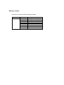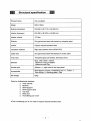
1
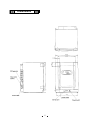
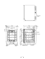
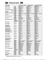
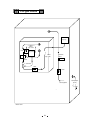
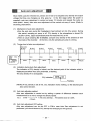
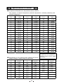
FILE No. Service Manual CO2 Incubator MCO-18AIC SM9910023 Contents Page Features ................................................................................................................................ 1 Structural specification .......................................................................................................... 2 Performance specification ..................................................................................................... 3 Control specification .............................................................................................................. 4 Dimensions........................................................................................................................ 5∼6 Electrical parts....................................................................................................................... 7 Temperature calibration ........................................................................................................ 8 CO2 calibration ...................................................................................................................... 9 Control specification ...................................................................................................... 10∼19 Wiring diagram .................................................................................................................... 20 Circuit diagram .................................................................................................................... 21 Components on PCB........................................................................................................... 22 Connection on PCB............................................................................................................. 23 CO2 gas circuit .................................................................................................................... 24 Prevention of contamination................................................................................................ 25 Auto zero adjustment .................................................................................................... 26∼27 Specifications of sensor ...................................................................................................... 28 Parts layout ................................................................................................................... 29∼31 MCO-18UVS installation procedure .............................................................................. 32∼35 Mounting procedure of MCO-21GC .............................................................................. 36∼39 How to replace water level sensor ...................................................................................... 40 MCO-18PS installation procedure................................................................................. 41∼42 MCO-18SB Setting procedure............................................................................................. 43 MCO-21SB Setting procedure............................................................................................. 44 Instruction manual ............................................................................................................... 45 Effective models This service manual is effective following models. Model name MCO-18AIC Model code 823 279 51 823 279 52 823 279 53 823 279 54 823 279 56 Voltage and Frequency 115V 60Hz 220V 50Hz 220V 60Hz 230V 50Hz 230V 50Hz Features 1. PID control with micro-computer. This unit has PID control (Proportional Integrate Differential) accurate controls internal temperature, as well as air sensor system monitoring internal temperature. 2. Infrared CO 2 sensor installed. Infrared CO 2 sensor is not affected by humidity. 3. UV sterilization system (Option) Water and the circulating chamber air in the humidifying pan are sterilized by UV lamp. Optional setting of light mode is available. 4. Rounded Ball corners. Inside chamber wall made by stainless steel and its corner made rounded type. This made cleaning easier and de-contamination. 5. Reduce contamination. Inside chamber material is made by anti-bacteria SUS. Appearance and durability are almost same with ordinary SUS. Anti-bacteria SUS has effect same as copper alloyed. (except for humidity pan) 6. Expandability (Module concept) The control circuit is adopted commonly with MCO-20AIC. 7. Options (1) Castor with adjustor (roller base: MCO-18RB) (2) CO 2 gas tank switcher (assembled in unit: MCO-21GC) (3) Extra stainless steel shelves (1 shelf + 1 shelf support basis :MCO-46ST) (4) Stacking plate for double-piled (MCO-18PS) (5) UV sterilization system (MCO-18UVS) Note ; Model name M CO – 18 A I C C: Copper alloy anti-bacteria stainless steel I: Infrared CO 2 sensor A: Air jacket 18: Chamber capacity (170L) CO: CO 2 Incubator M: Medical equipment 1 Performance specification Model MCO-18AIC Temperature: 5°C∼35°C and Humidity: Less than 80%RH (In ambient temperature is lower than 15°C, original performance cannot be always obtained) Temperature control range in Ambient temperature+5°C∼+50°C the unit (Settable range:0°C∼50°C) Temperature distribution in ±0.25°C Ú the unit Temperature variation in the ±0.1°C Ú unit 25 minutes or less Temperature recovery period (until the internal temperature is recovered to 36.5°C after door opened for 30 seconds) Ambient temperature humidity range CO2 level range 0∼20% CO2 level distribution range ±0.15% CO2 level recovery period 10 minutes or less (until the CO2 level is recovered to 4.5% after door opened for 30 seconds.) Internal humidity 95±5%RH Internal period humidity recovery 30 minutes or less (until the internal humidity is recovered to 90%RH after door opened for 30 seconds.) Supplied CO2 gas pressure 0.03MpaG (0.3kg/cm2G) when the gas supplied Power supply Single phase, local voltage Total power consumption 310W Total current 110-120VAC: Maximum 2.8A 220-240VAC: Maximum 1.4A Quantity of radiation Maximum 1120kJ/h Test condition: Set point: 37°C CO2 set point: 5.0% No load Ambient temperature: 20°C Ambient humidity: Approx.45% Ú Based on the measuring method on validation service manual. 3 Control specification Model MCO-18AIC Heating method Direct Heat + Air jacket (DHA) Temperature control system Microprocessor PID Sensor: temperature sensor (103AT-1) Detect and control the inside temperature directly. Temperature indication Digital display (resolution: 0.1°C) CO2 measuring system Infrared CO2 sensor, PID control CO2 level indication Digital display (resolution: 0.1%) Humidifying system Natural vaporization by water in humidify pan. Humidify pan: W293 x D407 x H41mm Inside air circulation Breeze circulation Alarm system High/low temperature alarm, high/low CO2 level alarm Both display for temperature and CO2 are flashing, and buzzer sounds intermittently after 15 min. Independent alarm for overheat Door lamp Door switch When outer door is opened: Inside fan OFF, CO2 valve OFF, (UV lamp * OFF) and heater OFF (only when door is kept opening for 1 min. or more) Remote alarm When an alarm is triggered: Remote alarm ON (Alarm and buzzer are interlocked.) Contact output: rating of contact 30VDC, 2A Self diagnosis function UV lamp control * Error code and internal temperature are displayed alternately. Buzzer and remote alarm contact ON Automatic ON-OFF control (changeable with Function mode) 1. Interlocked with the door: UV lamp ON for 5 min. after every door closed. 2. OFF mode (UV lamp does not turn on) * UV lamp is optionally provided. 4 Dimensions 5 6 Temperature calibration Note) When key lock mode is ON, calibration mode is disabled. (1) Press CAL key for approx. 5 seconds. rd (2) The top (the 3 ) digit of temperature display is flashing, other digits will go off. (3) Set the present correct temperature with key and key. Press ENT key. (4) The display will automatically revert to the present temperature. [Example] If the internal temperature display shows 37.0°C (the set value) and the actual measured value is 36.8, j Press CAL key for approx. 5 seconds. k The “3” (top digit) of temperature display is flashing, other digits will go off. l Set the displayed value at 36.8°C of the actual measured value with key and key, then press ENT key. m The display will automatically revert to the present temperature. (Note) sIn temperature calibration, it is important to accurately measure the internal temperature. Particularly, for the thermometer used, its grade of accuracy should be than 0.5 class. The measure should be carried out at the center of the chamber. sThe temperature calibration range is between the set value ±1.0°C. If the value over this range is input, an error tone will be emitted, the input data will be ignored, and the display will revert to the present temperature. Therefore, if you need to calibrate more than 1.0°C, you should repeat above procedure several times. 8 CO2 Calibration Note) When key lock mode is ON, calibration mode is disabled. (1) Press CAL key for approx. 5 seconds. rd (2) The top (the 3 ) digit of temperature display is flashing, other digits will go off. (3) Press CAL key again. rd (4) The top (the 3 ) digit of CO2 density display is flashing, other digit will go off. (5) Set the present correct CO 2 density with key and key. Press ENT key. (6) The display will automatically revert to the present temperature. [Example] If the internal CO2 density display shows 5.0%(the set value), the actual measured value is 4.5, j Press CAL key for approx. 5 seconds. k The top digit of temperature display is flashing, and other digits will go off. l Press CAL key again. m The top digit of CO 2 density display is flashing, other digits will go off. n Set the displayed value at 4.5% of the actual measured value with and key, then press ENT key key. o The display will automatically revert to the present temperature. (Note) s In CO 2 calibration, if CO2 density display is less than 2.0%, an error tone will be emitted and the input data will be ignored, and the display will revert to the present temperature. s CO2 calibration should be done after CO2 density measuring was done at least three times after checked that there is no error of measurement. s This unit has auto zero adjustment function. It is necessary to check that the room installed the unit is not filled with CO2 gas. If the unit is installed in smaller room, be sure to change the room air timely. (Please request to your customers.) s CO2 calibration should be done in consideration of the difference for CO2 density meter. 9 Control specification 1. Key and switch BZ : When an alarm LED is flashing and the buzzer sounds, Buzzer and remote alarm output Force to turn off When an alarm lamp flashing and the buzzer does not sound, buzzer remains OFF. SET : Press once to enter the device into setting mode. Press twice to enter the device into CO2 level setting mode. Press third times to enter the device into over-heat protection temperature check mode. Press four times to return the device to internal temperature (PV) display. CAL : the 1st digit the In the setting mode, the device can be shifted the 2nd digit st 1 decimal place. In PV display, keep the key pressing 5 seconds or more to enter the key lock mode. : In the setting mode, the blinking digit counts up. : In PV display, keep the key pressing approximately 5 seconds to enter the device into the calibration mode, press again to enter the device into the CO2 calibration mode. When the CO2 setting value (SV) is 0%, the device goes into PV display instead of the CO2 calibration mode. In the temperature calibration mode, input FXX with key and then press ENT key to enter the device into the function mode to obtain information of each mode. Note) During CO2 Auto Zero adjustment (the decimal point of indicator is flashing), the CO2 calibration will not be performed with beeping the buzzer for a second continuously even if ENT key is pressed. ENT A/B 2. : : During setting mode, CAL mode and Function mode, press the key to store the value. The function is not valid for the unchangeable values. The key is available only in optionally Auto-changer mode in F08. In Auto-changer mode, press the key to switch the cylinder in use to another one. Lighting A or B indicates as the cylinder in current use. (If the Auto-changer mode is not installed, the cylinder switcher lamp does not activate) When the cylinder in use is emptied, automatically switches to another one. At the time the lamp of cylinder emptied will blink, and the lamp of another one will illuminate. (Ex: When the CO2 cylinder in current used is emptied, the lamp cylinder A switches to blink, and then the lamp cylinder B will illuminate) Temperature control Setting range : 0°C~+50°C Display range : 0°C~+99.9°C Setting method : Press the SET key. Change to the desired value with key and key, then press the ENT key. The value will be stored and then the device shifts to CO2 setting mode. Out of the range: When a value is set out of the range and ENT key is pressed, buzzer sounds 1 second (continuously) and the previous value is still remained. Control : PID control Alarm : When the PV is SV±1°C or higher, the display digit blinks. After 15 minutes later, buzzer sounds and remote output turns ON. 10 3. CO2 control Setting range Display range Setting method : 0%~20% : 0%~99.9% : Press SET key twice. Change to the desired value with key and key, then press ENT key to store the value. Then the device shifts to the Overheat protection temperature check mode. Out of the range: 4. Control Control OFF : PID Control : When a value is set in 0.0%, CO2 display will be disappeared to be the Control OFF. Alarm : When the internal CO2 level deviates SV±1% or higher, CO2 display blinks. After the 15mininutes later, buzzer sounds and remote alarm terminal turns ON. Overheat protection temperature check mode Setting range : 35°C~51°C Setting method 5. When a value is set out of the range and ENT key is pressed, buzzer sounds 1 second (continuously) and the previous value is still remained. : Press SET key for three times to display the overheat protection temperature on PV display and “HI” on CO2 display. Press SET key again to return to PV display. Alarm, safety mode and self diagnosis In sensors malfunctions and CO2 control malfunctions, an error code and PV is displayed alternately. Note) The remote alarm is controlled in every a minute exceptionally in Auto Zero. That’s why the remote alarm control is delayed 4minutes (max) after an error is displayed. <Error code> E01: CO2 cylinder is empty E05: Temp. sensor is open circuit E06: Temp. sensor is short circuit E07: CO2 box temp. sensor is open circuit E08: CO2 box temp. sensor is short circuit E09: Ambient temperature sensor is open circuit E10: Ambient temperature sensor is short circuit E11: CO2 sensor output voltage is abnormal E12: Main heater is abnormal E13: Bottom heater is abnormal E14: Door heater is abnormal E15: CO2 sensor box heater is abnormal E16: SSR for each heater is open circuit E17: Sample pump and/or Auto zero pump malfunction E18: UV lamp malfunction (a lamp blown out, a glow lamp unfitted, etc) The description of error codes are follow: E01 : CO2 cylinder is empty When the CO2 level is not 0.2% or more in a minute even though the valve is opened, “E01” and “Internal temperature “ are displayed alternately, and buzzer sounds intermittently. The definite action that CO2 cylinder is empty, repeats twice, therefore it takes approximately 2minutes to display an error after the cylinder would be emptied. 11 E05,E06 : Temp. sensor malfunction (open / short circuit) When the micro-computer detects an internal temperature as 0°C or lower, it is judged as “open circuit” displaying alternately “E05” with PV and sounding intermittent buzzer. When the micro-computer detects an internal temperature as +60°C or higher, it is judged as “short circuit” displaying alternately “E05” with PV and sounding intermittent buzzer. Note) In E05 and E06, displayed PV is different from product’s actual temperature) E07,E08 : CO2 box temp. sensor malfunction (open / short circuit) See E05, E06 in details. (Note: In E07 and E08, CO2 valve is closed) E09, E10: Ambient temperature sensor malfunction (open / short circuit) See E05, E06 in details. E11 : CO2 sensor output voltage is abnormal When CO2 sensor box temperature is stable and high or low temperature alarm is not occurred, it is judged as CO2 sensor malfunction if CO2 output voltage is lower than 1000mV or higher than 4800mV. “E11” and “internal temperature” are displayed alternately, and buzzer sounds intermittently. At the time, CO2 valve is closed. E12 : Main heater is abnormal When high temperature alarm is activated, when the main heater is open circuit, and when the main heater SSR is short circuit, “E12” and an internal temperature are displayed alternately and buzzer sounds intermittently. An error is not displayed just after failed because the self-diagnosis for SSR and heater failure is done only in every 40min or in the power supplied. (Above description is also applied for E13 - E16) E13 : Bottom heater is abnormal When the bottom heater is open circuit, or SSR is short circuit, “E13” and an internal temperature are displayed alternately, and buzzer sounds intermittently. E14 : Door heater is abnormal When the door heater is open circuit, or SSR is short circuit, “E14” and an internal temperature are displayed alternately, and buzzer sounds intermittently. E15 : CO2 sensor box heater is abnormal When the CO2 sensor box heater is open circuit, or SSR is short circuit, “E15” and internal temperature are displayed alternately, and buzzer sounds intermittently. E16 : SSR is open circuit When any SSR of main heater, bottom heater, door heater and CO2 sensor box heater is open circuit, “E16” and an internal temperature are displayed alternately, and buzzer sounds intermittently. E17 : Sample pump and Auto zero pump malfunction In CO2 SV is 3.5% or higher and the current level is 3.5% or higher, if the difference of voltage between “during Auto Zero “ and “before Auto Zero” is 150mV or lower, it judges as “Sample pump and Auto zero pump malfunction”. “E17” and an internal temperature are displayed alternately and buzzer sounds intermittently. At the same time CO2 valve is closed. The judgement would be done in every Auto Zero adjusts, however, the judgement in the 1st interval in Auto Zero would be ignored. 12 E18 : UV lamp malfunction (UV lamp is optionally provided) When the time to turn the UV lamp on (F01) is set, the microcomputer checks the output voltage in UV detect circuit, that is detected 30seconds after the door was opened → shut. If the detected voltage is 0.2V or lower, it is judged as UV lamp malfunction. “E18” and “internal temperature “ are displayed alternately, at the time the buzzer sounds intermittently. Press BZ key to cancel the error. High temperature alarm: When the internal temperature is out of SV, OVERHEAT lamp illuminates displaying “PV” with “E12” (main heater malfunction) or “E16” (SSR for each heater is open circuit) alternately. The buzzer sounds intermittently. It is impossible to stop the buzzer sounding by BUZZER key. At the time heaters (main heater, bottom heater and door heater) will be OFF. Automatic temperature alarm When the internal temperature is ±1.0°C out of SV, all digits in temperature display blink and intermittent buzzer sounds with 15minutes delay. Automatic CO2 level alarm When the internal CO2 level is 1.0% out of SV, all digits in CO2 display blink and intermittent buzzer sounds with 15 minutes delay. CO2 Auto Zero adjustment calibration: See details in “Auto Zero adjustment”, Page 26. 6. Key lock function Lock mode : In PV display, keep pressing key (shift key) over 5 seconds to enter key lock mode, display will change to “L0”. Press key to set 1 ……… Key lock ON Press key to set 0 ……… Key lock OFF Press SET to memorize the set, then automatically returns to PV display. Note) In Key Lock ON, the device can enter into SET mode to check SV, however, the value cannot be changed. The device also cannot enter into Function mode. 7. Door alarm Display Safety operation 8. 9. : When the door is opened, DOOR lamp illuminates. When the door is closed, DOOR lamp goes off. When the door is opened, fan motor turns off, CO2 valve shuts off, (UV lamp turns off if it is optionally fitted). If the door left opened for 60seconds, the heater turns off. : Auto return Function : Calibration Temperature calibration : In setting mode, Key Lock mode and Function mode, if any key is not operated for 90 seconds or more, the display automatically returns to PV without storing the value to be changed. In PV display, press CAL key for approx. 5seconds to enter the device into temperature calibration mode. Input a proper value with key and key then press ENT key to store the value. Finally the device returns to PV display. 13 CO2 calibration 10. : In PV display, press CAL key for approx. 5seconds to enter the device into temperature calibration mode, then press CAL key again to enter the device into CO2 calibration mode. Input a proper value with key and key then press ENT key to recognize and store a span calibrated value. Finally the device returns to PV display. (a span adjustment) If CO2 level is lower than 0.9% or higher than 20% on the display, or if a value to calibrate is higher than 2.0%, the buzzer beeps to cancel the data input then automatically returns to PV display. During Auto Zero adjustment (the decimal point of the 2nd digit is blinking on CO2 display), CO2 calibration cannot be performed. Function mode F00: Simply pass through. F01: Time length of UV lamp illuminating is changed. (initial: 000) (UV lamp is optionally provided) F02: UV lamp 24hours sterilization mode set (UV lamp is optionally provided) F03: Service code input (code: 384) F04: UV lamp life span check (UV lamp is optionally provided) F05: Display the voltage in CO2 sensor F06: Change the output ratio of bottom heater (initial:12) F07: Change the output ratio of door heater (initial: 4) F08: Auto changer, DEMO mode, Auto Zero mode set (initial : 000) F09: Display a temperature in CO2 sensor box F10: Display a coefficient of adjustment value for CO2 zero point F11: Display a coefficient of adjustment value for CO2 span point F12: Display the temperature in ambient temperature sensor F13: Initialize non volatile memory F14: LEDs and drivers performance check F15: Display a value to adjust zero point in temperature (initial: 008) F21: Communication device address (ID) set (initial: 000) F22: Communication parameter set (initial: 000) F24: Interlock the remote alarm with buzzer (initial: 000) F25: Ring Back time set (initial: 030) F30: Display ROM version Direction for use: In PV display, press CAL key for 5seconds or more to enter the device into temperature calibration mode. Input a desired function code with key and key then press ENT key. F01: Time length of UV lamp illuminating is set. (initial: 0min, range:0~30min) Note) UV lamp is optionally provided. <Direction Input “F01” on the temperature display then press ENT key to show a present SV key and key then press for use> on the CO2 display. Input the desired value with ENT key to store the value. Finally returns to PV. If a value out of the range is input then ENT key is pressed, the buzzer beeps for a second continuously to keep the previous set. <Action> After the door is opened and shut, UV lamp illuminates in appointed time then automatically goes off. There is approx. 3~5seconds delay to active the mode, due the device would check water level in the humidify pan just after the door shut. With UV lamp illuminating, the lamp goes off if the door is opened. 14 F02: UV lamp 24hours sterilization mode set Note) UV lamp is optionally provided. <Direction Input “F02” on temperature display to show “000” on CO2 display. for use> Input “001” with key and key to enter the device into 24hours sterilization mode. At the time press ENT key displaying with “001” to simply return to PV display. <Action> When 24hours sterilization mode is set in F02, UV lamp starts illuminating and automatically goes off after 24hours has passed. In the middle of 24hours sterilization, if the door is opened, UV lamp goes off and 24 hours sterilization mode would be cancelled. If 24hours sterilization mode is reset in the middle in F02, the mode would start operation from the beginning. Note) UV indicator lamp should illuminate when UV lamp illuminates, so the indicator lamp illuminates if UV lamp is unfit. F03: Note that those who knows service code (384) should use F04 or the following functions (except for F21, 22, 24, 25 and 30). <Direction Input the following code to use the following functions. (code: 384) for use> Input “F03” on temperature display then press ENT key to show “000” on CO2 display. (“384” is appeared if service code has been already input) Input service code “384” with key and key, and press ENT key to return to PV display. Now F04 and the following functions are available. If F03 or a following function code instead of the above code is input in F03, for example if “F05” is input then ENT key is pressed, the continuous buzzer beeps for a second to return to PV display. In this case input the above code to enter the device into “F04” or a following function. Note) The above code is stored unless “000” is input in F03 or the mains is OFF. F04: Display life span of UV lamp Note) UV lamp is optionally provided. <Direction Input “F04” on temperature display and press ENT key to show UV lamp used for use> time (a period to turn UV lamp on) by unit of %. <Description> The microcomputer calculates UV lamp whole life span as 1000hours. A period to turn UV lamp on is displayed in the unit of %. For example, the period less than 5minutes is considered as 5minutes, the period of 6~30minutes is simply counted as they are. In 24hours mode, simply 24hours is added just after “001” is input and ENT key is pressed in F02, ignored with the cancel for 24hours mode caused by the door is opened in the middle. The added value is stored in the non-volatile memory in every 24hours. key Display the added value in F04 then display “000” on CO2 display with and key and press ENT key to clear the value. The display range is 0~260%. A value over than 260% is not added. If the added period is over than 1000hours, UV indicator on the control panel flashes to inform “UV lamp run down”. The “run down” is provided by the microcomputer’s calculation, it does not mean “the actual time to be UV lamp run down”. UV lamp life span 1000hours or less 1000hours or more UV indicator on the control panel UV lamp ON UV lamp OFF Illuminates Goes off Illuminates Flashes 15 F05: Display the voltage in CO2 sensor (A/D converter voltage in microcomputer on the main PCB) <Direction Input “F05” on temperature display and press ENT key to show the voltage in for use> CO2 sensor on CO2 display. Press ENT key to be Auto Zero forcibly performed within a minute. Since the 90seconds Auto Return is invalid in this mode, press ENT key to come to the end. F06: Adjust humidity level by changing the electricity output ratio in the bottom heater. (initial: 12, the range: 0~19) <Direction Input “F06” on temperature display and press ENT key to show a current SV on for use> CO2 display. Sum the value up to make humidify higher. Lessen the value to make humidify lower. Press ENT key to store the value and automatically returns to PV display. F07: Prevent dew condensation by changing the electricity output ratio in the door heater. (initial: 4, the range: 0~9) <Direction Input “F07” on temperature display and press ENT key to show a current SV on for use> CO2 display. If there is dew condensation on the door, sum the value on CO2 display up and press ENT key to store the value and automatically returns to PV. F08: Auto Zero and Auto Changer ON/OFF set, Demonstration mode set (initial: 000) In Auto Changer mode, both of CO2 cylinders are available when CO2 is requested to supply. A lamp of cylinder in current used (either lamp-A or lamp-B) is illuminated to switch manually one to another with A/B key. If the cylinder in current used is empty, automatically switches to another cylinder and the lamp of empty cylinder flashes. In Demonstration mode, SV for both temperature and CO2 are displayed, it seems to be under control. At the time the heater is not conducted and CO2 valve is not opened. (Demonstration mode is used in exhibitions.) In Auto Zero, zero adjustment for CO2 sensor is automatically performed based in ambient air. Auto Zero is performed per every 10minutes in 1 hour when the main power is supplied, after that it is performed per every 4hours. <Direction for Auto Changer mode setting (in the 3rd digit on CO2 display) use> Input “F08” on temperature display and press ENT key to show a current SV in the 3rd digit on CO2 display. The value “0” is the normal mode (Auto Changer is inoperative), the value “1” is Auto Changer is operative. Demonstration mode setting (in the 2nd digit on CO2 display) Input “F08” on temperature display and press ENT key to show a current SV in the 2nd digit on CO2 display. The value “0” is the normal mode (Auto Zero is operative), the value “1” is Demonstration mode is operative. Change the 2nd digit to a desired digit and press ENT key to return to PV display. Auto Zero setting (in the 1st digit on CO2 display) Input “F08” on temperature display and press ENT key to show a current SV in the 1st digit on CO2 display. The value “0” is the normal mode (Auto Zero is operative), the value “1” is Auto Zero is inoperative. Change the 1st digit to a desired digit and press ENT key to return to PV display. 16 F09: Display the temperature in CO2 sensor box <Direction for Input “F09” on temperature display and press ENT key to show the use> temperature in CO2 sensor box. If you press ENT key or leave for 90seconds, automatically returns to PV display. In SV is +45°C, CO2 valve turns OFF when the temperature is out of SV±2.0°C. Once the temperature retrieves in SV±2.0°C, Auto Zero is forcibly executed since the apparatus falls into the condition that the main power is supplied. When CO2 is not injected, the temperature in sensor box may be out of ±2.0°C, or it may be within 60minutes after the main power is supplied, or Auto Zero may be being executed. F10: Display a coefficient of adjustment value for CO2 zero point (initial: 500) <Direction for Input “F10” on temperature display and press ENT key to display a coefficient use> of adjustment value for CO2 zero point on CO2 display. If you press ENT key or leave the device for 90seconds, automatically returns to PV display. <Description> The condition is that CO2 sensor voltage should be adjusted in 4.0V when internal CO2 level is 0%. Perform Auto Zero and ensure the sensor output voltage should be approx. 4.0V when ambient air is got properly by the pump. At that time the value should be approx. “500”. If CO2 in the ambient air is several %, the value would be lower than “500” since CO2 sensor output voltage is lower than 4.0V. <Calculation> (CO2 sensor output voltage during Auto Zero pump performs / 4.0V) x 5000 Note) Only bigger three digits are displayed. e.g “5000” → displayed as “500” F11: Display a coefficient of adjustment value for CO2 span point (initial: 500) <Direction for Input “F11” on temperature display and press ENT key to display an use> adjustment value for CO2 zero point on CO2 display. If you press ENT key or leave the device for 90seconds, automatically returns to PV display. <Description> The value is adjusted when CO2 is calibrated. For example, calibrate CO2 with SV 4.5% when the CO2 level is displayed as 5.0%, however the actual level is 4.5%. At that time the value in F11 should be lower than “500”, ex “460”. If the value is abnormal, ex “999”, the actual internal level can be 1.0%, however the CO2 is displayed as 5.0%. F12: Display a temperature in ambient temperature sensor <Direction for Input “F12” on temperature display and press ENT key to display a use> temperature of ambient temperature sensor on CO2 display. If you press ENT key or leave the device for 90seconds, automatically returns to PV display. Note) This temperature is not synchronized with actual ambient temperature since it is affected by waste heat in electrical parts. (indicated approx. 4°C higher than the actual temperature) F13: Initialize the non-volatile memory (initial: 000) This function should be used only when data in the non-volatile memory cannot be restored owing to unexpected events (ex: noise). Do not use in normal condition. <Direction for Input “F13” on temperature display and press ENT key to display “000” on use> CO2 display, then change the 1st digit to “1” and press ENT key to initialize all the data in non-volatile memory. 17 Followings are initial values in non-volatile memory: Internal temperature SV : 37.0°C CO2 level SV : 0.0% Balance value of humidifying heater (F06) : 12 Balance value of door heater (F07) :4 : 5000 CO2 zero adjustment data (F10) : 5000 CO2 span data (F11) Internal temperature zero adjustment data (F15) : 008 Key Lock data : Key Lock OFF : Auto Changer OFF Auto Changer data (the 3rd digit in F08) : Demo Mode OFF Demo Mode data (the 2nd digit in F08) : Auto Zero ON Auto Zero (the 1st digit in F08) Input “F13” on temperature display and press ENT key to display “000” on CO2 display, then change the 1st digit to “2” and press ENT key to initialize CO2 zero adjustment data and CO2 span data in non-volatile memory. Note) Service code should not be initialized. F14: Check the performance for LED, drivers <Direction for Input “F14” on temperature display and press ENT key to perform with lamp use> and the all digits flashing at every 0.5seconds intervals. Press ENT key to stop performance. If there is no key operation for approx. 90seconds, automatically comes to end F15: Display an adjustment value for temperature zero point (initial: 0.8°C) <Direction for Input “F15” on temperature display and press ENT key to display an use> adjustment value on CO2 display for temperature zero point. If you press ENT key or leave the device for 90seconds, automatically returns to PV display. (Ex.) In “37.0” is displayed on the control panel and actual temperature is “37.8”, if you perform temperature calibration (actual temperature “37.8” is input), “+0.8” would be housed in F15. In Function Mode, input F15 and press ENT key to display the value on CO2 display. F21: Set serial communication ID (initial: 000) <Direction for Input “F21” on temperature display and press ENT key to show “000” on CO2 use> display. Then input the value that identifies the product (serial communication ID Number) and press ENT key to set serial communication ID. The range is 000~255. (000: communication OFF) F22: Set serial communication mode (initial: 000) <Direction for Input “F22” on temperature display and press ENT key to show “000” on CO2 use> display. Then change the 3rd digit to set the communication mode. 0: Local (initial) Control mode (the 3rd digit) 1: Remote 0: 2400bps Baud rate (the 2nd digit) 1: 4800bps 2: 9600bps F24: Interlock the remote alarm with buzzer (initial: 000) <Direction for Input “F24” on temperature display and press ENT key to show “000/001” on use> CO2 display. Then change the 1st digit to “000” to set the interlock mode. 000: Buzzer/Remote alarm not interlocked 001: Buzzer/Remote alarm interlocked 18 F25: Ring Back time set (initial: 030 (30min), the range: 0~60min) <Direction for Input “F25” on temperature display and press ENT key to set current Ring use> Back delay time. Change the 2nd digit to set delay time in the range of 0~60min. Note) Ring Back time set, F25 = “000” means BZ would not comeback (in former spec) F30: Display the ROM version <Direction for Input “F30” on temperature display and press ENT key to show current ROM use> version on CO2 display. 11. Bottom heater control In order to shorten the recovery time of humidity, conduct electricity to humidity heater as follows. • In the ordinary, the maximum electricity conduct to bottom heater should be in the ratio of 80%. • When the internal temperature is SV-0.4~-0.6deg, conduct 80% electricity to humidify heater for 10minutes (max). SV in F06 is applied except for above temperature. • 80% electricity conduct should not be performed in the following cases: 1) The period until an internal temperature reaches to SV-0.2deg after the power is supplied 2) The period until an internal temperature reaches to SV-0.2deg after the door is left opened continuously for 60seconds or more. 12. Door heater control Ordinarily, conduct electricity to door heater in the same ratio with main heater. SV in F07 is applied. 13. Remote alarm: remote alarm contact In normal condition ……... Open In alarming condition …… Close Note) The recovery time after BZ key is pressed and linkage between remote alarm and buzzer are depending on F24, F25 setting. 14. Storing in non-volatile memory 2 times comparison method: When the main power is supplied, a data storing in non-volatile memory is called for 2 times to compare. If the data 1st called coincides with the data of 2nd called, the data would be stored in RAM. Otherwise, the comparison would be repeated until the one coincides with another. 15. Temperature offset value The difference between temperature sensed in temperature control sensor and temperature in internal 1/2H should be offset: Offset value: +0.8°C 16. Example for displays Current temperature +36.2°C CO2 level +5.0% Set temperature +37.0°C Auto Zero adjusting Function Auto Zero adjustment value 5021 F03 CO2 gas error (Service code input) Bottom heater ratio Lock Mode 004 L0 19 E01 Wiring Diagram 20 Circuit Diagram 21 Components on PCB 22 Connection on PCB The following shows connections of connector (CN) on main PCB. Connector Connects to Use Power transformer To supply the power to PCB. Between #1−#2, AC8.5V CN1 To supply the power AC36V for Auto #3 GND zero air pump. #4 and #5, AC18V Power supply CN2 To supply the power to PCB. Between #1−#2(GND), DC5V CN3 CO2 sensor CN4 #1−#2 #3−#4 #5−#6 CN6 Door switch CN8 Switch, display PCB (CN101) CN9 CN10 Input from CO2 sensor. Overheat protect sensor Temperature sensor CO2 box temp. sensor To detect the door opening. #1−#2 CO2 valve #3−#4 CO2 auto changer valve (option) Remote alarm output #1−#2 Open during normal operation CN11 Communication board (option) CN12 #1−#2 #3−#4 CN13 Buzzer CN14 UV lamp relay (option) CN15 Water sensor CN101 Display PCB (CN8) To measure the temperature of each parts. To control CO2 valve ON and OFF. Output of remote alarm contact Auto zero air pump Air pump hinge sub heater For alarm To check water level in humidify pan. The following shows connections of connector (CN) on power PCB. Connector Connects to CN301 CN302 C303 Use Main PCB #1: Heater for heat control (5pcs) #3: Bottom heater (4pcs) #5: Front panel heater, Door heater (2pcs) #1: CO2 A, B heater #3: Agitating fan motor 23 To control heater To control the sensor BOX temperature. To control the pump for circulation. CO2 gas circuit Auto Zero air pump 25mm Cap. tube Filter Air pump 25mm Cap. tube Solenoid valve CO2 sensor T -connector Filter Filter Gas supplied < Back view > 24 Sample port (front) Prevention of contamination In servicing for CO2 incubator, it is important to prevent from contamination. (1)More than 90% of contamination in CO2 incubator is caused by mold. Mold is a kind of true fungi, it has high increasing power under high temperature and high humidity. Accordingly, it is easy for mold to increase inside CO2 incubator. Those increased mold eat up culture (mainly animal cell), eventually precious test sample will be killed. Cell that is independent from ecosystem is also independent from immune system, it has no immunocompetence at all. (2)Precautions for mold increasing There are many cases that mold is increasing by eating fat on the fingers as a source of nutrient in CO2 incubator. Therefore, cBe sure to wash and sterilize your hands prior to servicing. Use 70% ethanol. dIn installing, sterilize the inside wall and shelves after removing shelves, duct, humidifying pan and so on with 70% ethanol. (3)In the case that mold is already increasing. Sterilize the interior (walls) and shelves with 70% ethanol after removed all items from the chamber as same as (2)-d above. And you should sterilize again after 24 hours once sterilized, when the root of spore is geminated, because it is too difficult to remove spore of mold. Repeat sterilization is effective. NOTICE In general, stainless steel is known that it is not easy (hard) to rust. However depends on the conditions, rust might generate. When you remove rust, we recommend the following agents. Besides, the surface may become foggy. Recommended agent: 1. Cream cleanser ªGif¼ (Nippon Leva) 2. Picasso #SUS300-W (Chemical YAMAMOTO) <Picasso has greater capability of clean for rust than Gif.> 25 CO2 gas density calibration and Auto Zero adjustment MCO-18AIC provides both the manual CO2 gas density calibration and the automatic Auto Zero adjustment. 1. CO2 gas density calibration When either the CO2 density SV or the display value is not match with the actual value, calibrate CO2 gas density according with “CO2 calibration” (Page 9) to input the actual value again. 2. Auto Zero adjustment Refer to “Auto Zero adjustment” 3. The relation the CO2 gas density calibration with the Auto Zero adjustment The description is as follow.(Ex: CO 2 density = 5%) Ideal line for the set value and the actual value. (Note) In fact, it could not make a straight line due to the characteristics of the sensor. Actual density(%CO2) 5 0 Point calibrated by CO2 gas density calibration 0 5 Set density(%CO2) Point calibrated by auto zero adjustment 27 Specifications of sensor Temperature/Resistance for temperature sensor 103AT-1 The measure of internal temperature (internal temperature, overheat protection) and ambient temperature Temperature Resistance Temperature Resistance Temperature Resistance (°C) (kΩ) (°C) (kΩ) (°C) (kΩ) 0 27.28 17 13.57 34 7.19 1 26.13 18 13.06 35 6.94 2 25.03 19 12.56 36 6.70 3 23.99 20 12.09 37 6.47 4 22.99 21 11.63 38 6.25 5 22.05 22 11.20 39 6.03 6 21.15 23 10.78 40 5.83 7 20.29 24 10.38 41 5.63 8 19.48 25 10.00 42 5.44 9 18.70 26 9.63 43 5.26 10 17.96 27 9.28 44 5.08 11 17.24 28 8.94 45 4.91 12 16.55 29 8.62 46 4.75 13 15.90 30 8.31 47 4.59 14 15.28 31 8.02 48 4.44 15 14.68 32 7.73 49 4.30 16 14.12 33 7.46 50 4.16 Specification for CO2 density/output voltage in IR sensor Followings are reference voltage. In actual use, it is no problem if the calibration could be done in reliable CO2 density. (Output voltage = amplify value in main PCB) CO2 density (%) R13 output voltage(V) CO2 density (%) R13 output voltage(V) CO2 density (%) R13 output voltage(V) 0.0 4.00 8.0 2.87 16.0 2.47 1.0 3.74 9.0 2.80 17.0 2.43 2.0 3.54 10.0 2.75 18.0 2.40 3.0 3.37 11.0 2.69 19.0 2.37 4.0 3.23 12.0 2.64 20.0 2.33 5.0 3.12 13.0 2.59 6.0 3.02 14.0 2.55 7.0 2.94 15.0 2.51 28 Parts layout agitating fan motor monitoring hole Auto Zero air pump Remote alarm terminal CO2 valve filter CO2 gas inlet 29 remote alarm terminal sensor BOX transformer for PCB noise filter sensor BOX temp. sensor thermal fuse CO2 IR sensor power comsumption resistance (R13) sensor BOX heater 30 CO2 gas inject port Overheat protect sensor Temp. sensor Inlet port of Sampling gas for CO2 sensor Return port of Sampling gas for CO2 sensor UV lamp connection port Water level sensor 31 MCO-18UVS Installation Procedure Kit of MCO-18UVS g 1 UV label h1 UV caution label c 1 UV lamp i1 UV door switch caution label d1 UV lamp cover q 1 Name plate f1 ballast & glow assy r 1 Patent label e6 screws (M 4) Procedure 1. Unplug the unit and make sure that power is not supplied to the unit. 2. Remove the duct from inside the unit, then take off 2 caps and 2 screws shown in Fig. 1. 4. Take out two insulations for the UV lamp lead wire hole shown in Fig. 3. The insulation can be taken out easily by pushing it from inside of the chamber. Keep the insulation for the future use again. Screw Cap Insulation Fig.1 3. Take off the rear cover shown in Fig. 2. Fig.3 5. Set the UV lamp to the hole and make sure to be fitted properly. Fix the UV lamp cover with 2 screws enclosed in this kit. e Screw Rear cover Fig.2 c UV lamp d UV lamp cover Fig.4 32 6. Replace the duct. Place the humidifying tray, then cover the tray with the humidifying tray cover as shown in Fig. 5 8. Remove a cap shown in Fig. 7. By using 4 screws enclosed with this kit, fix the ballast/glow assy as shown in Fig. 7. Humidifying tray cover e Screw Fig.5 f ballast & glow assy Cap Fig.7 7. Replace the insulation into the UV lamp lead wire hole with the wire passed through the cut on the insulation. See Fig.6 UV lamp lead wire Insulation Fig.6 33 9. Connect each lead wire connector of ballast/glow assy, as shown in Fig. 8. Connect after removing the cover. Cover BLUE GREEN Fig.8 10. Attach the labels. i UV door switch j Name plate caution label g UV label h UV caution label Fig.9 34 k Patent label 11. Set the UV lamp ON period through control panel When using UV lamp option, it is needed to set the UV lamp ON period. Refer to the following procedure. Description of operation Key Indication after operation operated 1 Turn the power switch ON. The current chamber temperature is displayed. 2 Press CAL key for 5 seconds. 3 By pressing key and key, set the figure to F01. 4 CAL F01 Press ENT key. ENT 5 6 The left digit in the temperature indicator is flashed. By pressing key and key, set the figure to 005 (5 minutes of ON period). Press ENT key. ENT In CO2 density indicator, "000" is displayed and the right digit is flashed. F01 000 F01 005 The setting of UV lamp ON time is memorized and the current chamber temperature is displayed. <<NOTE>> • The UV lamp ON time is settable between 0 to 30 minutes. However, it is recommended to set 5 minutes in general. • The UV lamp ON time is settable between 0 to 30 minutes (000 to 030). The UV lamp is not turned ON if the setting is 000. • The UV lamp is turned off when the outer door is opened while the lamp is on. The lamp is turned on for pre-set duration after the outer door is closed. • The condensation in the chamber can be caused and/or the chamber temperature distribution can be affected due to the heat from UV lamp when the setting of UV lamp ON time is longer than 5 minutes or the only the outer door is opened/closed repeatedly. In such case, the life of UV lamp is shortened. • In the procedure 2 above, pressing CAL key for 5 seconds causes the calibration mode. In this mode, it is possible to calibrate the temperature and CO2 density, and miss operation of the key may affect the basic performance of the unit. Take care of the key operation. Even if the key is operated wrongly, the unit returns to the current value display mode automatically when no key is operated for 90 seconds. In this case, the setting not entered by pressing ENT key is not effective. 12. Check that the UV lamp is turned on. Check the UV lamp is turned on by the following procedure: Procedure 1 Open the outer door and push the door switch with the inner door is closed. 2 Check that the UV indicator on the control panel is on after a few seconds. 3 Check the visible blue light from the front side of the humidifying pan cover. (Check the light with the inner door closed. Never look at the UV light directly.) 7FB6P104035003 35 Mounting Procedure of MCO-21GC (Automatic CO2 cylinder changer for MCO-20AIC/18AIC) Parts list e connecting port for c CO2 valve assy i tube band (S) CO2 gas pipe f nut g spring washer d y-pipe assy j screw k tube h tube band (L) l tube L100 (Used for MCO-18AIC ONLY) Before mounting This kit is applicable to both MCO-20AIC and MCO-18AIC. Following procedure is necessary only when mounting to MCO-18AIC. 1. Remove the tube band on the CO2 valve assy c, and then remove the hose and capillary. 2. Attach the tube L100 l and fix the tube by the tube band removed in procedure 1. Make sure the tube band is fixed firmly to prevent gas leakage. c CO2 valve assy tube band l tube L100 Remove the tube and capillary Fig.1 36 Fix the edge by the tube band Mounting procedure 1.Disconnect the power cable and make sure that the unit is not supplied with the power. 2.Remove the rear cover by unscrewing the 6 fixing screws. 3.Fix c by using the enclosed screws(j). 4.Remove cap and fix e with f and g. 5.Connect the wiring harness of CO2 valve B to wiring harness from CN9 on Main board. 6.Disconnect upper tube of CO2 valve A. Connect CO2 valve A and CO2 valve B and tube X by using d as shown in Fig.4. 7.Connect bottom tube of c to e. 8.Connect e with CO2 gas supply line B by using k. 9 .Fix tubes securely using h and i as shown in Fig.4. 10.Replace the rear cover. Rear cover Fig.2 NOTE: Every tubes should be connected surely to prevent CO2 leakage. Tube X CO2valve B white CO2 valve A Main board CN9 CO2 gas supply line A cap yellow CO2 gas supply line B Fig.4 Fig.3 37 Setting procedure of Control panel. When use MCO-21GC(the automatic CO2 cylinder changer system), it is necessary to set the MCO-20AIC/18AIC automatic gas switching mode according to the following procedures. Description of operation 1 Key operated Turn the power switch ON. - 2 Press CAL key for 5 seconds. CAL 3 By pressing key and set the figure to F03. 4 Press ENT key. By pressing key and set the figure to 384 6 Press ENT key. 7 8 9 000 F03 384 ENT The current chamber temperature is displayed. CAL The left digit in the temperature indicator is flashed. key, F08 Press ENT key. In CO2 density indicator, "0**" is displayed and the F 0 8 right digit is flashed. 0** F08 1** By pressing key and key, set only the left digit figure to 1. NOTE:Don't change center digit figure and right digit figure. 11 In CO2 density indicator, "000" is displayed and the F 0 3 right digit is flashed. key, ENT 10 The left digit in the temperature indicator is flashed. F03 Press CAL key for 5 seconds. By pressing key and set the figure to F08 The current chamber temperature is displayed. key, ENT 5 Indication after operation " Press ENT key. ENT 38 * " means "0" or "1". Setting of MCO-21GC is finished. The current chamber temperature is displayed. CO2 gas supply line indicator A is lighted. Procedure for automatic gas switching operation check. When the installation of MCO-21GC is completed, check the automatic gas switching operation according to the following to the following procedures. procedure 1 Stop the gas supply of cylinder A and use cylinder B only for CO2 gas supply. 2 Turn on the power switch of MCO-20AIC/18AIC and set 37decC and 0%. Turn on CO2 gas supply line indicator with CO2 gas supply line switching key. 3 Wait for 1 hour approx , until the machine can control the CO2 density. (It takes about 1 hour from turning on the power switch until CO2 control is enabled.) 4 Set CO2 density 5% and check the CO2 inject lamp turns on. NOTE: In case of low ambient temperature, it may take more than 1 hour until the machine can control CO2 density and the CO2 inject lamp turns on. 5 Check the E01(CO2 gas cylinder empty alarm) and buzzer turn on about 2-7minutes later from the CO2 inject lamp's turning on. 6 Check the CO2 gas density indicator reaches to the set value 5% and keep it stably. NOTE: CO2 density control is interrupted when automatic calibration of CO2 sensor is activated and the decimal point of CO2 density indicator blinks. 7 All the procedure are completed. Shut down the CO2 supply of cylinder A and cylinder B. Turn off "E01" display with the buzzer key and select cylinder A with CO2 gas supply line switching key. Turn off the main power switch. Refer to the MCO-20AIC/18AIC instruction manual for usage of MCO-21GC 7FB6P104036000 39 HOW TO REPLACE WATER LEVEL SENSOR. 1.Unplug the unit and check that power is not supplied to the unit, then take the rear cover off. 2.Unfasten the connectors for lead wire and take out the insulation for the lead wire hole. Water level sensor lead wire connector Insulation for the lead wire hole Fig.1 3.Take out the duct from inside. 4.Unfasten the 2 screws to remove unit of water level sensor and installation grommets for water level sensor. 5.replace water level sensor. Note Be sure to set the water level sensor to the right direction. 6.Place back the water level sensor, Water sensor installation grommet as before. 7.Place back the insulation material to the hole for the lead wire. Note Be careful for the length of lead wire for water level sensor inside the unit Length is connect 2nd binder is located where it touches the water level sensor grommet. (refer to Fig.3) 3.Put the rear cover in place screw Water level sensor Installation grommet Water level sensor Fig.2 Water level Sensor grommet binder Fig.3 40 MCO-18PS Installation Procedure Kit of MCO-18PS c2 Stacking plate B d2 Stacking plate A e4 Protective sticker f4 Screws Procedure <When stacking 2 units of MCO-18AIC> 1. Turn off the power switch and disconnect a plug of each unit. 2. Check that the lower unit is level. 3. Apply the protective sticker enclosed in this kit at each corner on the top of the lower unit to avoid scratches or damage. 4. Fix the stacking plate A at 2 locations on the top front of the lower unit by using 2 screws enclosed in this kit. 5. Remove the front panel on the upper unit by unscrewing the 4 fixing screws and then disconnect the wires and gas tube. 6. Stack the unit so that both units can be aligned straight. Also check the upper unit is level. If it is not level, keep the unit even by adjusting the leveling legs. 7. Secure the upper unit with the stacking plate A and 2 screws enclosed in this kit. 8. Remove 2 hooks on the rear side of the lower unit by unscrewing each 2 fixing screws. 9. Remove 1 screw on the bottom right and left on the rear side of the upper unit. 10. Fix the stacking plate B at the right and left on the rear of the lower and upper unit with 3 screws removed in step 8 and 9. 11. Replace the front panel on the upper unit after connecting the wires and gas tube. 12. Fix the stacked unit to the wall with 2 hooks on the rear of the upper unit and rope or chain. Front panel Stacking plate B Hook Stacking plate A Protective sticker Fig.1 41 <When stacking of combination as shown in Fig.2.> MCO-17AIC MCO-17AC MCO-15AC MCO-18AIC MCO-17AIC MCO-17AC MCO-15AC MCO-18AIC MCO-17AIC MCO-17AC MCO-15AC MCO-17AIC MCO-17AC MCO-15AC Fig.2 1. Turn off the power switch and disconnect a plug of each unit. 2. Check that the lower unit is level. 3. Apply the protective sticker enclosed in this kit at each corner on the top of the lower unit to avoid scratches or damage. 4. Stack the unit so that both units can be aligned straight. Also check the upper unit is level. If it is not level, keep the unit even by adjusting the leveling legs. 5. Remove 2 hooks on the rear side of the lower unit by unscrewing each 2 fixing screws. 6. Remove 1 screw on the bottom right and left on the rear side of the upper unit.(only MCO-18AIC) 7. Fix the stacking plate B at the right and left on the rear of the lower and upper unit with 3 screws removed in step 5 and enclosed in this kit. 8. Fix the stacked unit to the wall with 2 hooks on the rear of the upper unit and rope or chain. Ú Stacking plate A is not used. Stacking plate B Hook Protective sticker Fig.3 WARNING Select a level and sturdy floor having enough strength for installation of stacked module. Never stack 3 or more units. Take care not to drop or tip over the unit when stacking as this can cause injury or damage of the unit. 7FB6P104038000 42 MCO-18SB Setting Procedure (Stacking base for stacking MCO-18AIC/17AIC/17AC/15AC on MCO-175/175M) 1.Remove four clips on the top of lower unit. 2.Fasten four “iFixing screws A” tentatively from where the clips were remove. 3.Set the “cStacking base” and fix with screws tentatively fastened. 4.Stick the “hProtective sticker” on the “cStacking base” as shown in Fig.1. 5.In case of stack MCO-18AIC Put the upper unit on it. Fix the upper unit with “dFront fixing plate”, “gRear fixing plate ”. (eRear fixing plate R and fRear fixing plate L are not used.) In case of stack MCO-17AIC/17AC/15AC Put the upper unit on it. Fix the upper unit with “dFront fixing plate”, “e Rear fixing plate R”, and “f Rear fixing plate L”. (gRear fixing plate is not used.) 6.Check the both units are level. NO. i c d e f g h i j j Parts name Stacking base Front fixing plate Rear fixing plate R (for 17AIC/17AC/15AC) Rear fixing plate L (for 17AIC/17AC/15AC) Rear fixing plate (for 18AIC) Protective sticker Fixing screw A Fixing screw B Q’ty 1 2 1 1 2 2 4 8 h c (f) g i (e) j i j d Fig.1 Fig.2 7FB 6 P104 041 00 0 43 MCO-21SB Setting Procedure (Stacking base for stacking MCO-18AIC/17AIC/17AC/15AC on MCO-20AIC) 1. Stick the “jBuffer rubber” at each corner on the bottom of “cStacking base”. Stick the “iProtective sticker” on the “cStacking base” as shown in Fig.1. 2. Attach the”dBase mounting plate” onto the top of MCO-20AIC by using “lFixing screw B”. 3. Remove 2 hooks on the rear side of MCO-20AIC. 4. Fix the “cStacking base” onto the top of MCO-20AIC by using “kFixing screw A” and 2 screws removed in step 3. 5. In case of stack MCO-18AIC Put the upper unit on it. Fix the upper unit with “eFront fixing plate”, “hRear fixing plate ”. (fRear fixing plate R and gRear fixing plate L are not used.) In case of stack MCO-17AIC/17AC/15AC Put the upper unit on it. Fix the upper unit with “eFront fixing plate”, “f Rear fixing plate R”, and “g Rear fixing plate L”. (hRear fixing plate is not used.) 6. Check the both units are level. No. k c c d e f g h i j k l l i j Fig.1 Parts name Q’ty 1 Stacking base Base mounting plate 1 Front fixing plate 2 Rear fixing plate R (for 17AIC/17AC/15AC) 1 Rear fixing plate L (for 17AIC/17AC/15AC) 1 Rear fixing plate (for 18AIC) 2 Protective sticker 2 Buffer rubber 4 Fixing screw A 2 Fixing screw B 10 j (g) k h c (f) d hook l l l e Fig.2 44 Fig.3 7FB 6 P104 040 00 0