1
immedi
ately
VP
immedi
ately
immedi
ately
immedi
ately
immedi
ately
immedi
ately
VP
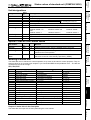
I11="1": switched on)
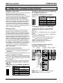
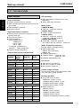
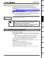
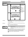
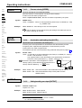
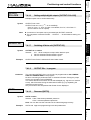
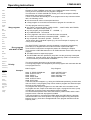
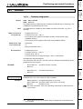
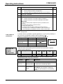
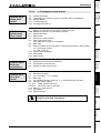
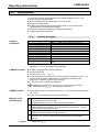
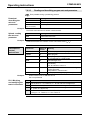
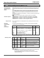
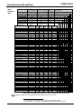
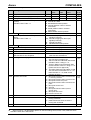
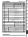
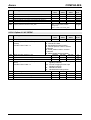
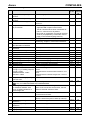
P233 Setting the optimization display S13
1...255
immedi
ately
P234 Setting the optimization display S14
1...255
immedi
ately
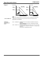
="0": single axis (when P250=0) or slave on IPM (P250=1 ... 9)
="1": COMPAX as master ="2": COMPAX as slave on a COMPAX master
VP
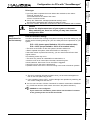
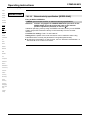
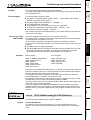
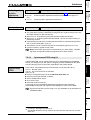
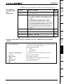
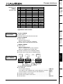
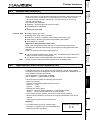
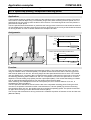
P243 HEDA operation
mode
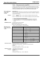
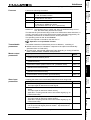
P245 Allocating outputs
O1 - O8 to the
HEDA bus
P246 Allocating outputs
O9 - O16 to the
HEDA bus
P247 - P250
51
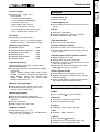
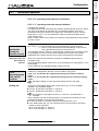
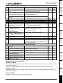
O1 (1) [1] • O2 (2) [2] • O3 (4) [3] • O4 (8) [4]
O5 (16) [5] • O6 (32) [6] • O7 (64) [7] • O8 (128) [8]
P245 = sum of valencies of the outputs allocated to the HEDA bus
immedi
ately
O9 (1) [1] • O10 (2) [2] •O11 (4) [3]
O13 (16)[5] •O14 (32)[6] •O15 (64)[7]
P246 = sum of valencies allocated to the HEDA bus
immedi
ately
Output (valency) [bit no.]:
Output (valency) [bit no.]:
HEDA parameter
•O12 (8) [4]
• O16 (128) [8]
VP
Counting in bits starting with bit 0.
171
Unit
hardware
Connector
assignment /
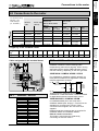
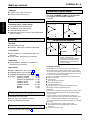
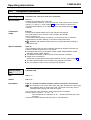
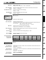
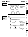
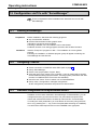
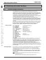
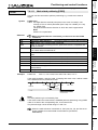
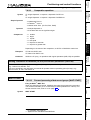
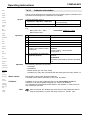
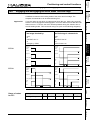
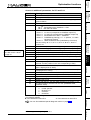
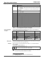
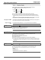
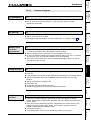
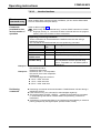
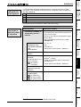
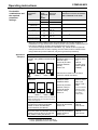
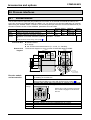
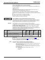
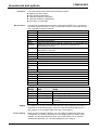
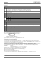
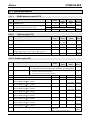
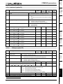
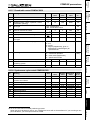
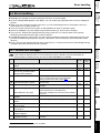
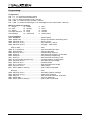
P218 Error cutout
Bit 0 ="0" E57 active ="1" E57 switched off
Standard value: P218=0 (E57 active and E65 Bit 1 ="0" E65 switched off ="1" E65 active
not active)
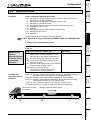
P219 Emergency stop
=0 no evaluation of emergency stop input on COMPAX-M
input on COMPAX- =7 emergency stop input on COMPAX-M active
M/
=128 synchronous STOP on COMPAX XX0X and no evaluation of
Synchronous STOP
emergency stop input on COMPAX-M
on COMPAX XX00 =135 synchronous STOP on COMPAX XX0X with evaluation of
emergency stop input on COMPAX-M
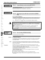
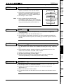
Input (valency) [bit no.]:
I1 (1) [1] • I2 (2) [2] • I3 (4) [3]
P221 Freely assigning
I4 (8) [4] • I5 (16) [5] • I6 (32) [6]
standard inputs
P221 = sum of valencies of all free inputs you want.
with a "1"
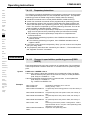
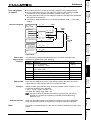
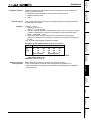
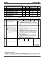
Output (valency) [bit no.]:
O1 (1) [1] • O2 (2) [2] • O3 (4) [3] • O4 (8) [4]
P223 Assigning outputs
O5 (16) [5] • O6 (32) [6] • O7 (64) [7] • O8 (128) [8]
O1 - O8 to the
P223 = sum of valencies of the OUTPUT WORD outputs
OUTPUT WORD
command with a "1"
Output (valency) [bit no.]:
O9 (1) [1] • O10 (2) [2] • O11 (4) [3] • O12 (8) [4]
P224 Assigning outputs
O13 (16)[5] • O14 (32)[6] • O15 (64)[7] • O16 (128) [8]
O9 - O16 to the
P224 = sum of valencies of OUTPUT WORD outputs
OUTPUT WORD
command with a "1"
Output (valency) [bit no.]:
O1 (1) [1] • O2 (2) [2] • O3 (4) [3]
P225 Freely assigning
O4 (8) [4] • O5 (16) [5] • O6 (32) [6]
standard outputs
P225 = sum of valencies of all free outputs you want.
with a "1"
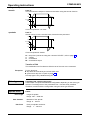
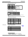
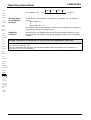
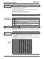
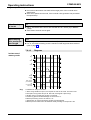
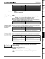
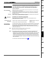
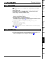
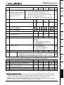
P227 Assigning special Bit 151="0": O2 is assigned standard function (=no warning).
functions to
Bit 1="1": O2 is assigned with "Idle display" function.
outputs
Bit 4="0": O5 is assigned standard function (position reached with
evaluation of P14)
Bit 4="1": O5 is assigned function O5, toggles when position reached.
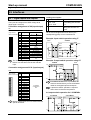
P229 Speed threshold for "idle indicator" function (only
0
0
255
switched on if P227 bit 1="1")
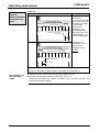
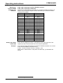
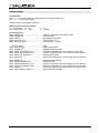
P232 Controlling external position adjustment using
=0: I11 can be freely assigned
I11
=4: I11 switches the external position
adjustment (I11="0": switched off and
immedi
ately
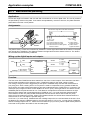
Technical data
immedi
ately
Configuration
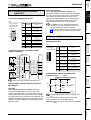
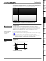
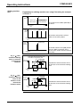
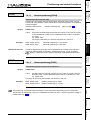
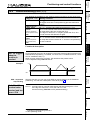
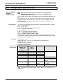
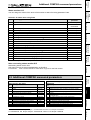
P216 Limit switch position E1 is approached when "0": motor turning clockwise
...
"1": motor turning anti-clockwise
P217 Limit switch mode
"0": without "1": with limit switch
Positioning and
control functions
Valid
as of..
Optimization
functions
Maximum
value
Interfaces
Minimum Default
value
value
Accessories /
options
Unit
Status
Meaning
Parameters
No.
Error list
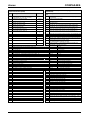
COMPAX parameters