1
PML 1000 Operating Instructions
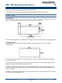
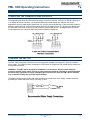
CONNECTING THE STATUS INPUTS
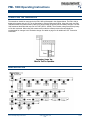
There are two status (logic) inputs on the PML 1000. These inputs can be used with voltage free contacts, such
as relays or switches. Open collector transistor outputs can also be used. The inputs are active low i.e. activated
by applying a short circuit between the status input and status common terminals. The diagrams below show
some typical applications. Note that these inputs are not isolated from the PML 1000s input circuit.
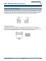
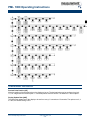
High Speed Analog Output
A buffered DC output of the demodulated LVDT input signal is provided by the PML 1000. The output level is
dependent upon the transducer excitation and the sensitivity of the LVDT. The output is not calibrated or
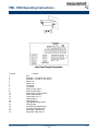
scaleable and it is recommended that it is used for diagnostic purposes only. Use terminals 20 (a-out +), and 13
(a-out -), to connect the High-Speed Analog output. This output is not isolated from the LVDT.
APP-01025, Rev A
PML 1000 Operating Instructions
www.meas-spec.com
5/18
1109