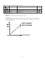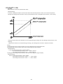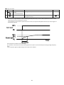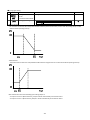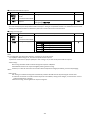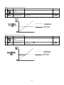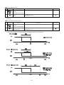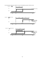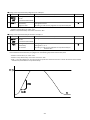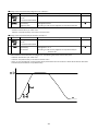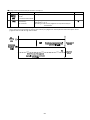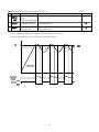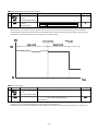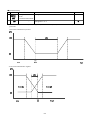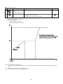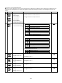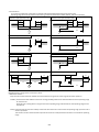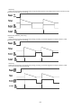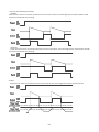
1
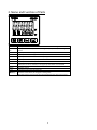
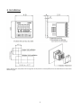
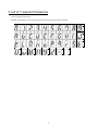
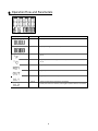
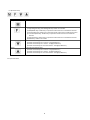
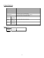
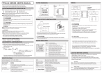
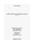
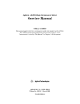
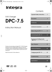
Digital Controller
TTM‐i4N
User’s Manual
Contents
1. Precautions upon Usage
2
2. Name and Function of Parts
4
3. Installation
5
3.1 Dimensions
3.2 Installation and Dimensions of Panel Cut
5
5
4. Wiring
6
4.1 Terminal Layout for Wiring
4.2 Caution upon Wiring
6
6
5. List of 7-segment Characters
7
6. Operation Flow and Parameters
8
6.1 Display Sections
6.2 Operation Keys
6.3 Operation Flow
6.4 Parameters
6.5 Other Displays
8
9
9
21
69
7. List of Models
70
8. Before Performing a Control
71
9. Specifications
72
9.1 General Specifications
9.2 Rated Values and Performance
72
73
10. Maintenance and Inspection
1
74
1. Precautions upon Usage
Please read this section before use.
For the safe use of this product, please take note of the following:
This operation manual should be kept by the user of this product.
★Safety Precautions
For the safe use of the product and to prevent possible accident or damage, the following warning signs are used in this
operation manual depending on their level of importance and risk. Please follow each instruction in order for you to
use the product safely.
★Warning Symbols and Their Meanings
Danger
Improper handling of the
equipment may cause fatality or
serious injury for an impending
reality.
Caution
Improper handling of the
equipment may cause injury
or physical damage on it.
Warning
Improper handling of the
equipment may cause fatality or
serious injury.
Reminder
Care should be taken for
ensuring safety.
Matters that are indicated as “Caution” can also turn into serious accidents, depending on the situation.
Please follow all instructions described herein for the safe use of this product.
★Example of Symbols
General caution, warning or
prohibition without
particularity
Instruction on ground
connection for the
equipment with safety
grounding terminals
Hazard of pinched fingers
on a particular portion of the
equipment
Possible injury caused by
touching a particular portion
of the equipment under
specific conditions
Unspecific behaviors of
general users
Hazard of injury due to high
temperature under specific
conditions
Hazard of an electric shock
under specific conditions
Hazard of injury such as an
electric shock due to
disassembling or
modification of the
equipment
Hazard of burst under
particular conditions
2
Warning
Improper wiring to the equipment may cause a failure, such as fire. Upon completion of wiring,
ensure to verify the proper wiring before turning on electricity.
Do not turn on electricity until all wiring is complete. Do not touch portions of high voltages such as
power supply terminals, as an electric shock may be resultant.
Install appropriate protective circuits externally if a failure or abnormality of the equipment may seriously affect
related systems.
Do not use the equipment out of the specified range, as it may fail or catch fire.
Do not under any circumstance to modify or disassemble the equipment, as a failure may be caused, resulting
fire or an electric shock.
Do not use the equipment in ambience of flammable or explosive gases.
Caution
Do not use the vacant terminals for wiring.
Do not use a pointed object to operate keys.
Do not turn on the power supply until wiring is fully complete in order to prevent an electric shock,
failure or malfunctioning. For replacing a component connected on the equipment, ensure to turn off
the power supply. For turning back on the power supply, do so after all wiring is complete.
Ensure not to trap heat in the space surrounding the equipment in order to provide sufficient heat release.
Do not put a metal piece or similar inside the equipment. A fire, an electric shock or failure may be caused.
The equipment is designed for instrumentation. For its use in environments of high voltages or intense noises,
take appropriate measures on the side of user’s equipment.
The equipment is designed for controlling physical values, such as temperatures, on general industrial facilities.
Do not use it for subjects of control that may seriously affect human life.
Turn off the power supply before cleaning the equipment, and wipe it with a soft dry cloth. Do not use
thinners, as they may cause deformation or discoloration of the equipment.
The equipment may cause radio disturbances in domestic settings. User is required to take appropriate
measure.
Ensure to tighten terminal screws at specified torque. Insufficient tightening the screws may cause an electric
shock or fire.
Ensure to observe precautions listed in this manual for the use of the equipment.
Reprinting or duplicating this manual is prohibited.
This manual may be revised without prior notice.
Important Reminder Regarding Export Trade Control Order
Please investigate the client and the purpose of his or her usage to make sure that the product will not be used as a weapon of
mass destruction (e.g., for military purposes and use in military facilities).
3
2. Name and Function of Parts
PV
SV
°F
°C
RDY
OUT
AL1
AL2
M Key
F Key
▲▼keys
Displays the character of current measurement value or setting mode screen.
Displays the selected input value of setting value, output value, or setting mode
screen.
Lights up when the setting value is a temperature data with the unit of °F.
Lights up when the setting value is a temperature data with the unit of °C.
Lights up when the control mode is RDY (ready).
Lights up when OUT1 (Output 1) is turned ON.
Lights up when Event Output 1 is turned ON.
Lights up when Event Output 2 is turned ON.
If heat/cool control is selected, it also lights up when OUT2 is turned ON.
Switches screens.
Executes functions that are being set.
Increases or decreases (to change) the setting value.
(Pressing each key continuously will increase/decrease the value more quickly.)
4
3. Installation
3.1 Dimensions
3.2 Installation and Dimensions of Panel Cut
Attach the product either vertically (upper surface of the product should be facing up) or horizontally.
How to Attach: Place the product into an angle hole of the panel cut and completely insert the attachment from the surface
without any gap.
5
4. Wiring
4.1 Terminal Layout for Wiring
4.2 Caution upon Wiring
Warning: Turn the power OFF before wiring to avoid the risk of electric shock.
Caution:This product will not perform any control for approximately 4 seconds after turning its power ON
(produces no output).Please be careful if you will be using this product as an interlock circuit.
・Check the wiring with the operation manual to make sure that input terminal, power terminal, option terminal, and other
such terminals are connected correctly.
・ Upon wiring, use the crimped terminal that fits with the M3.5 screw (squeeze the wire into the center of the terminal).
・For the connection between the resistance temperature detector and the product, use the wire with the resistance of less
than 5Ω (per wire).
・For the connection between the thermocouple and the product, use the prescribed compensating lead wire or the wire
itself.
・ Use the radio shield wire if the product is to be used near the noise source. Do not wire the input-output line in the same
duct or conduit tube.
・Separate the input-output signal line from both power and load lines with the distance of at least 50cm.
・ Do not connect anything to the blank terminal.
6
5. List of 7-segment Characters
< List of 7-segment Characters >
Numbers and alphabets used in parameter symbols and settings are described as follows:
0
1
2
3
4
5
6
7
8
9
A
B
C
D
E
F
G
H
I
J
K
L
M
N
O
P
Q
R
S
T
U
V
W
X
Y
Z
−
Blank
7
6. Operation Flow and Parameters
6.1 Display Sections
Display Sections
PV Display Section
Color
White
Description
• Displays measurement values and characters that have been set.
SV Display Section
Green
• Displays setting values and manipulated variables.
°F
Yellow
• Lights up when the setting value is a temperature data with the unit
of °F.
°C
Yellow
• Lights up when the setting value is a temperature data with the unit
of °C.
RDY Display
Yellow
• Lights up when the control mode is RDY.
OUT Display
Yellow
• Lights up when OUT1 is turned ON.
AL1 Display
Yellow
• Lights up when Event 1 Output is turned ON.
AL2 Display
Yellow
• Lights up when Event 2 Output is turned ON.
If heat/cool control is selected, it also lights up when OUT2 is turned ON.
8
6.2 Operation Keys
Operation Keys
M Key
F Key
DOWN Key
UP Key
Description
• Switches screens.
• Executes functions that are being set.
1) Digit Navigation Key (selected digit blinks): Usable in all modes.
2) RUN/READY Key: Usable only in operation mode. Click once to enable the function.
3) AT Start/Stop Key: Usable only in operation mode. Click once to enable the function.
4) Timer Start/Reset Key: Usable only in operation mode. Click once to enable the
function.
5) Alarm Reset Key: Usable only in operation mode. Click once to enable the function.
6) ENTER Key: Usable in all modes.
• Decreases the setting value.
(Pressed consecutively for 0.5–5secs.: 1 digit/100msecs.)
(Pressed consecutively for 5–10secs.: 10 digits/100msecs.)
(Pressed consecutively for more than 10secs.: 100 digits/100msecs.)
• Increases the setting value.
(Pressed consecutively for 0.5–5secs.: 1 digit/100msecs.)
(Pressed consecutively for 5–10secs.: 10 digits/100msecs.)
(Pressed consecutively for more than 10secs.: 100 digits/100msecs.)
6.3 Operation Flow
9
6.3.1 Operation Mode
PV
SV
PV
SV
PV
SV
PV
SV
PV
SV
PV
SV
PV
SV
PV
SV
PV
SV
PV
SV
1200
1. Controlled Temperature Setting
0
↓M Key
**** 2. Priority Screen 1
****
↓M Key
**** 3. Priority Screen 2
****
↓M Key
**** 4. Priority Screen 3
****
↓M Key
**** 5. Priority Screen 4
****
↓M Key
**** 6. Priority Screen 5
****
↓M Key
**** 7. Priority Screen 6
****
↓M Key
**** 8. Priority Screen 7
****
↓M Key
**** 9. Priority Screen 8
****
↓M Key
**** 10. Priority Screen 9
****
↓M Key
Back to 1.
10
6.3.2 Protect Setting Mode
PV
SV
PTLV
0
1. Protect Level Setting
6.3.3 Priority Screen Parameter Mode
PV
SV
PV
SV
PV
SV
PV
SV
PV
SV
PV
SV
PV
SV
PV
SV
PV
SV
PV
SV
SET0
PRI
1. Setting Mode Selection Screen
↓M Key
PRI1 2. Priority screen 1 setting
OFF
↓M Key
PRI2 3. Priority screen 2 setting
OFF
↓M Key
PRI3 4. Priority screen 3 setting
OFF
↓M Key
PRI4 5. Priority screen 4 setting
OFF
↓M Key
PRI5 6. Priority screen 5 setting
OFF
↓M Key
PRI6 7. Priority screen 6 setting
OFF
↓M Key
PRI7 8. Priority screen 7 setting
OFF
↓M Key
PRI8 9. Priority screen 8 setting
OFF
↓M Key
PRI9 10. Priority screen 9 setting
OFF
↓M Key
Back to 1.
11
6.3.4 Input Parameter Mode
PV
SV
PV
SV
PV
SV
PV
SV
PV
SV
PV
SV
PV
SV
SET1
INP
1. Setting Mode Selection Screen
↓M Key
INP 2. Input type setting
00
↓M Key
PVG 3. PV compensation gain setting
100
↓M Key
PVS 4. PV compensation zero setting
0
↓M Key
PDF 5. Setting of Input Filter
00
↓M Key
DP 6. Decimal point setting
0
↓M Key
C/F 7. Temperature unit setting
*C
↓M Key
Back to 1.
12
6.3.5 Key Function Parameter Mode
PV
SV
PV
SV
PV
SV
PV
SV
SET2
KEY
1. Setting Mode Selection Screen
↓M Key
FU 2. Function key function setting
00
↓M Key
LOC 3. Key-lock setting
0
↓M Key
ALRS 4. Alarm reset
0 0
↓M Key
Back to 1.
13
6.3.6 Control Parameter Mode
PV
SV
PV
SV
PV
SV
PV
SV
PV
SV
PV
SV
PV
SV
SET3
CNT
1. Setting Mode Selection Screen
↓M Key
SLH 2. SV limiter upper limit
1200
↓M Key
SLL 3. SSV limiter lower limit
0
↓M Key
MD 4. Control mode setting
RUN
↓M Key
CNT 5. Control type setting
020
↓M Key
DIR 6. Tuning type setting
0
↓M Key
MV1 7. Manipulated Variable of Output 1
00
M key
PV
SV
PV
SV
PV
SV
PV
SV
PV
SV
PV
SV
TUN
1
8. Setting of Tuning Type
※1
↓M Key
ATG 9. AT coefficient setting
※1
10
PV
SV
C1
1
19. Sensitivity setting for OUT1※2
↓M Key
PV
SV
↓M Key
ATC 10. AT sensitivity setting
※1
CP1
0
M Key
2
↓M Key
AT 11. AT start/stop
※1
OFF
↓M Key
P1 12. Proportional band setting for OUT1
※1
30
↓M Key
I 13. Integral time setting
※1
0
↓M Key
14
20. OFF point position setting for
OUT1※2
↓
PV
SV
PV
SV
PV
SV
PV
SV
PV
SV
D
0
14. Derivative time setting
※1
↓M Key
T1 15. Proportional cycle setting for OUT1
※1
20
↓M Key
ARW 16. Setting of Anti-reset Windup
※1
1100
↓M Key
MLH1 17. Operating amout limiter upper limit for OUT1
※1
1000
↓M Key
MLL1 18. Operating amout limiter lower limit for OUT1
※1
00
M key
PV
SV
PV
SV
PV
SV
PV
SV
PV
SV
PV
SV
LOP1
0
21. Setting of the Loop Abnormality Judgment Time of Output 1
↓M Key
PS1 22. Setting of the Loop Abnormality PV Variation of Output 1
※3
0
↓M Key
TS1 23. Setting of the Loop Abnormality PV Threshold of Output 1
※3
0
↓M Key
FDT1 24. Protection OFF timer time setting for OUT1
※2
0
↓M Key
NDT1 25. Protection ON timer time setting for OUT1
※2
0
↓M Key
MV2 26. Manipulated Variable of Output 2
※4
00
M key
PV
SV
PV
SV
27. Proportional band setting
for OUT2
※4 ※5
↓M Key
T2 28. Proportional cycle setting
for OUT2
20 ※4 ※5
↓M Key
P2
100
PV
SV
PV
SV
15
31. Setting of the Sensitivity of Output
2
※4 ※6
↓M Key
CP2 32. OFF point position setting for
OUT2
0 ※4 ※6
↓M Key
C2
1
↓
PV
SV
PV
SV
MLH2
1000
29. Operating amout limiter upper limit for OUT2
※4 ※5
↓M Key
MLL2 30. Operating amout limiter lower limit for OUT2
※4 ※5
00
M key
PV
SV
PV
SV
PV
SV
PV
SV
PV
SV
PV
SV
PV
SV
PV
SV
PV
SV
PV
SV
LOP2
0
33. Setting of the Loop Abnormality Judgment Time of Output 2
※4
↓M Key
PS2 34. Setting of the Loop Abnormality PV Variation of Output 2
※4 ※7
0
↓M Key
TS2 35. Loop anormaly PV threshold for OUT2
※4 ※7
0
↓M Key
FDT2 36. Protection OFF timer time setting for OUT2
※6 ※4
0
↓M Key
NDT2 37. Protection ON timer time setting for OUT2
※6 ※4
0
↓M Key
BMP 38. Enable/Disable Balance-less Bump-less Function
1
↓M Key
PBB 39. Manual reset setting
※1
00
↓M Key
DB 40. Dead band setting
※4
0
↓M Key
RMP 41. SV Ramp time setting
00
↓M Key
PWZ 42. Control backup function setting
※1
00
↓M Key
Back to 1.
※1 … This will not be displayed if the output type of Output 1 is ON/OFF control.
※2 … This will not be displayed if the output type of Output 1 is PID control.
※3 … This will not be displayed if the loop abnormality judgment time of Output 1 is “0.”
※4 … This will not be displayed if the output type of Output 2 is “None” or “Event 2 Output.”
※5 … This will not be displayed if the output type of Output 2 is ON/OFF control.
※6 … This will not be displayed if the output type of Output 2 is PID control.
※7 … This will not be displayed if the loop abnormality judgment time of Output 2 is “0.”
16
6.3.7 Event 1 Output Parameter Mode
PV
SV
PV
SV
PV
SV
PV
SV
PV
SV
PV
SV
PV
SV
PV
SV
PV
SV
SET4
AL1
1. Setting Mode Selection Screen
↓M Key
A1F1 2. Event 1 Function Setting 1
000
↓M Key
A1H 3. EV1 alarm upper limit setting
※8 ※9
0
↓M Key
A1L 4. EV1 alarm lower limit setting
※8 ※10
0
↓M Key
A1C 5. EV1 alarm sensitivity setting
※8
0
↓M Key
A1T 6. EV1 alarm delay timer setting
※11
0
↓M Key
A1F2 7. EV1 alarm function 2 setting
000
↓M Key
A1F3 8. EV1 alarm function 3 setting
00
↓M Key
A1P 9. EV1 alarm polarity setting
0
↓M Key
Back to 1.
※8 … This will not be displayed if Event 1 function is turned OFF.
※9 … This will not be displayed if Event 1 function will not be used at the maximum limit.
※10 … This will not be displayed if Event 1 function will not be used at the minimum limit.
※11 … This will not be displayed if Event 1 functions 1 and 2 are turned OFF.
17
6.3.8 Event 2 Output Parameter Mode
PV
SV
PV
SV
PV
SV
PV
SV
PV
SV
PV
SV
PV
SV
PV
SV
PV
SV
SET5
AL2
1. Setting Mode Selection Screen
※12 ※13
↓M Key
A2F1 2. Event 2 Function Setting 1
※12
000
↓M Key
A2H 3. EV2 alarm upper limit setting
※12 ※14 ※15
0
↓M Key
A2L 4. EV2 alarm lower limit setting
※12 ※14 ※16
0
↓M Key
A2C 5. EV2 alarm sensitivity setting
※12 ※14
0
↓M Key
A2T 6. EV2 alarm delay timer setting
※12 ※17
0
↓M Key
A2F2 7. EV2 alarm function 2 setting
※12
000
↓M Key
A2F3 8. EV2 alarm function 3 setting
※12
00
↓M Key
A2P 9. EV2 alarm polarity setting
※12
0
↓M Key
Back to 1.
※12 … This will not be displayed when the model of B option is not specified.
※13 … This will not be displayed when the output type of Output 2 is other than “Event 2 Output.”
※14 … This will not be displayed when Event 2 function is set to “OFF.”
※15 … This will not be displayed when Event 2 function will not be used at the maximum limit.
※16 … This will not be displayed when Event 2 function will not be used at the minimum limit.
※17 … This will not be displayed when Event 2 functions 1 and 2 are set to “OFF.”
18
6.3.9 Timer Parameter Mode
PV
SV
PV
SV
PV
SV
PV
SV
PV
SV
PV
SV
PV
SV
SET6
TIME
1. Setting Mode Selection Screen
↓M Key
TMO 2. Timer output setting
0
↓M Key
TMF 3. Setting of Timer Function
※18
1
↓M Key
H/M 4. Setting of the Unit of Timer
※18
1
↓M Key
TSV 5. Setting of SV Start Permission Range
※18 ※19
0
↓M Key
TIM 6. Time setting
※18
00:00
↓M Key
TIA 7. Remaining time monitor
※18
00:00
↓M Key
Back to 1.
※18 … This will not be used when Timer Output is set to “Timer OFF.”
※19 … This will not be displayed when Timer function is other than “SV Start.”
19
6.3.10 LCD Parameter Mode
PV
SV
PV
SV
PV
SV
PV
SV
SET7
LCD
1. Setting Mode Selection Screen
↓M Key
LLV 2. Brightness setting
100
↓M Key
LRFT 3. Dimming function setting
0
↓M Key
LRLV 4. Dimming Brightness setting
5
↓M Key
Back to 1.
20
6.4 Parameters
6.4.1 Operation Mode
Character
Name
Operation Mode
Description
Mode that is usually used by PV/SV
1
ControlledTemperature
(SV) Settings
2
3
4
5
6
7
8
9
10
Priority Screen 1–9
Setting Range: SLL–SLH
Setting Unit: °C or °F
Displays the screen that is set at Priority Screen.
Initial Value
0
6.4.2 Protect Setting Mode
Character
1
PTLV
Name
Protection Setting Mode
Setting of the Level of
Protection
Description
Mode that sets the protect level
0 No Protection
1 ・ Settings of SV/Priority Screen are changeable
・ Setting mode parameter blinds parameters other
than the following:
PV compensation zero setting
Alarm reset
AT start/stop
Proportional band setting for OUT1/2
Integral time setting
Derivative time setting
Sensitivity setting for OUT1/2
EV1/EV2 alarm upper limit setting
EV1/EV2 alarm lower limit setting
2 ・ Only settings of SV are changeable
・Priority screen is with display/settings that are
non-changeable
・ All setting mode parameters will be blinded
3 ・SV is with display/settings are non-changeable
・Priority screen is with display/settings that are
non-changeable
・ All setting mode parameters will be blinded
21
Initial Value
0
6.4.3 Priority Screen Setting Mode
■ Priority Screen Setting
Character
1
2
3
4
5
6
7
8
9
10
SET0
PRI
PRI1
PRI2
PRI3
PRI4
PRI5
PRI6
PRI7
PRI8
PRI9
Name
Setting Mode Selection Screen
Priority Screen Setting Mode
Description
Settings about Priority Screen
Initial Value
Priority screen 1 setting
・
・
・
Priority screen 9 setting
Sets the parameter to be displayed on a priority screen
Screen 1–9
OFF
Presetting frequently-used parameters and other such parameters that the user wishes to display allows the user to quickly
display these parameters by simply pressing the M key during operation mode.
Can set up to 9 screens.
Select “OFF” to disable the priority screen.
22
6.4.4 Input Parameter Mode
■Input type setting
Character
1
2
SET1
INP
INP
Name
Setting Mode Selection
Screen
Input Parameter Mode
Input type setting
Description
Initial Value
Settings about Input
Setting Range: 00–06, 10, 11
See Input Type Setting Table for detail
00
Input Type Setting Table
Setting
No.
00
Input Type
K
Thermocouple
Connect
ion
-10°C–1710°C
0°C–1700°C
-210°C–410°C
-199.9°C–410.0°C
-210°C–1310°C
-199.9°C–999.9°C
-200°C–400°C
-199.9°C–400.0°C
-200°C–1300°C
-199.9°C–999.9°C
TC
-10°C–1710°C
0°C–1700°C
1°C
TC
-20°C–1802°C
0°C–1800°C
1°C
-200°C–530°C
-199.9°C–530.0°C
-200°C–520°C
-199.9°C–520.0°C
-200°C–500°C
-199.9°C–500.0°C
-200°C–500°C
-199.9°C–500.0°C
06
10
Pt100
RTD
11
JPt100
RTD
02
03
04
05
Designated
Resolution
-200°C–1372°C
-199.9°C–999.9°C
-200°C–850°C
-199.9°C–850.0°C
TC
J
Thermocouple
R
Thermocouple
T
Thermocouple
N
Thermocouple
S
Thermocouple
B
Thermocouple
01
Setting Range
Measurement Range
-210°C–1382°C
-199.9°C–999.9°C
-210°C–860°C
-199.9°C–860.0°C
TC
TC
TC
TC
23
1°C/0.1°C
1°C/0.1°C
1°C
1°C/0.1°C
1°C/0.1°C
1°C/0.1°C
1°C/0.1°C
■PV compensation gain setting /Zero Setting of PV Correction
Character
1
3
SET1
INP
PVG
4
PVS
Name
Setting Mode Selection
Screen
Input Parameter Mode
Description
Settings about Input
PV compensation gain
setting
PV compensation zero
setting
Setting Range: 0.50–2.00
Setting Unit: Times
Setting Range: -199–999 or -199.9–999.9
Setting Unit: °C or °F
Initial Value
100
0
●PV compensation gain setting
[Function]
Multiplies PV (measurement value) of input with the correction value.
[Sample Setting]
In case PV is displayed as 90°C in an environment where the actual temperature is 100°C, PV can still be adjusted to
100°Cby setting the gain of PV correction to 1.11 (times). [Computation formula = 90°C(before PV correction) x 1.11
times = approximately 100°C]
24
[Function]
Adds correction value to PV (measurement value).
[Sample Setting]
In case PV is displayed as 90°Cin an environment where the actual temperature is 100°C, PV can still be adjusted to
100°Cby zero-setting the PV correction to 10 (°C). [Computation formula = 90°C(before PV correction) + 10°C= 100°C]
※ Numerical formula for the combination of “PV compensation gain setting” and “Zero Setting of PV Correction” is the
following:
“(Before PV Correction x PV compensation gain setting) + Zero Setting of PV Correction = After PV Correction”
Caution:
1) Setting the gain of PV correction greater may cause instability of the measurement value.
2) Setting the gain of PV correction to less than x1 will change the range of display.
[Sample Setting]
If the input of K thermocouple is -199.9°C–999.9°C:
PV compensation gain setting: x0.5 → “-100.0°C–500.0°C”
PV compensation gain setting: x0.1 → “-20.0°C–100.0°C”
3) Setting the zero setting of PV correction to less than 0 will change the range of display.
[Sample Setting]
If the input of K thermocouple is -210°C–1382°C:
Zero setting of PV correction: +100°C → “-110°C–1382°C”
Zero setting of PV correction: -100°C → “-210°C–1282°C”
25
■ Setting of PV Filter
Character
1
5
SET1
INP
PDF
Name
Setting Mode Selection
Screen
Input Parameter Mode
Setting of Input Filter
Description
Initial Value
Settings about Input
Setting Range: 0.0–99.9
Setting Unit: Second
00
[Function]
A function to programmatically realize CR filtering effect by performing a primary delay operation for PV of the input.
Filter effect will be set through time constant.
(Time constant is a time that was spent before PV to reach up to approximately 60% when the input has changed in a
step-by-step manner)
※The purposes of PV filter are the following:
① The effect of the electrical noise that was applied to the input can be minimized by eliminating the high-frequency
noise.
② The response against sudden change of the input can be delayed.
26
■ Decimal point setting
Character
1
6
SET1
INP
DP
Name
Setting Mode Selection
Screen
Input Parameter Mode
Decimal point setting
Description
Initial Value
Settings about Input
0 Without Decimal Point
0
00 With Decimal Point (Disabled for R/S/B
thermocouple)
Note: Switching °C/ °F may activate the limiter, such as SLH and SLL, and change each setting value.
■ Temperature unit setting
Character
1
7
SET1
INP
C/F
Name
Setting Mode Selection
Screen
Input Parameter Mode
Temperature unit setting
Description
Initial Value
Settings about Input
*C Celsius
*F Fahrenheit
Note: Switching °C/ °F may activate the limiter, such as SLH and SLL, and change each setting value.
27
*C
6.4.5 Key Function Parameter Mode
■ Function key function setting
Character
1
SET2
KEY
2
FU
Name
Setting Mode Selection
Screen
Key Function Parameter
Mode
Function key function
setting
Description
Settings about Key Function
Function Settings
*0 No Function
*1 Digit Shifting Key
*2 RUN/READY Key
*3 AT Start/Stop Key
*4 Timer Start/Reset Key
*5 Alarm Reset Key
*6 ENTER Key
Initial Value
00
Setting of the Length of Time in which the Key Is Being Pressed
0* None
1* Key is pressed for 1 second
2* Key is pressed for 2 seconds
3* Key is pressed for 3 seconds
4* Key is pressed for 4 seconds
5* Key is pressed for 5 seconds
・ Function Settings
1) Digit Shifting Key
the F key is pressed. This allows the user to change the
setting smoothly.
2) RUN/READY
Pressing the F key will switch the control mode from start to stop and vice versa.
3) Start AT/Stop AT
It serves as the key to start/stop automatic tuning during the control of PID.
4) Start/Reset Timer
It serves as start/reset key when the timer setting is set to manual start. It also serves as start/reset key for the timer
operation that was ended.
5) Reset Alarm
Allows the user to reset the event output condition.
6) ENTER
Uses the F key as the key to memorize the setting value.
Note 1: Proceeding to the next parameter without memorizing the changed setting will cause the resumption of the
previous setting.
Note 2: To change the function from ENT to another function, press the F (ENT) key after selecting the other function.
・ Setting of the Length of Time in which the Key Is Being Pressed
Allows the user to set the length of time the key needs to be pressed before the F key takes effect.
28
■ Key Lock Settings
Character
1
SET2
KEY
3
LOC
Name
Setting Mode Selection
Screen
Key Function Parameter
Mode
Key-lock setting
Description
Settings about Key Function
0 No Key Lock
1 Lock All
2 Lock Operation Mode
3 Lock All Modes Except for Operation Mode
※Protect Level Setting will not be subjected to key lock
Initial Value
0
Changing of setting value through △ and ▽ keys is prohibited for parameters that are locked.
■ Alarm reset
Character
1
SET2
KEY
4
ALRS
Name
Setting Mode Selection
Screen
Key Function Parameter
Mode
Alarm reset
Description
Settings about Key Function
0
0
1
1
0
1
0
1
No ongoing event
Event 1 is ongoing
Event 2 is ongoing
Both event 1 and 2 are ongoing
Screen that Resets the Output of Event 1/Event 2
※ Reset the output by pressing the F key for 1 second.
(Lights turn off instantaneously upon resetting the alarm.)
29
Initial Value
0 0
6.4.6 Control Parameter Mode
■ Minimum/Maximum Limit of SV Limiter
Characte
r
1
2
SET3
CNT
SLH
Name
Setting Mode Selection
Screen
Control Parameter Mode
Description
Initial Value
Settings about Control
SV limiter upper limit
Setting Range: Minimum setting range-Maximum setting range
1200
Provided that the difference between SLH and SLL
must be more than 5°C(or °F).
Setting Unit: °C or °F
3
Setting Range: Minimum setting range-Maximum setting range
SLL SV limiter lower limit
0
Provided that the difference between SLH and SLL
must be more than 5°C(or °F).
Setting Unit: °C or °F
・ Setting Range of the Maximum Limit of SV Limiter
When inputting thermocouple/resistance temperature detector: (SLL+5) up to maximum limit of setting range [°C]
(setting of the position of decimal point is 0)
: (SLL+5.0) up to maximum limit of setting range [°C]
(setting of the position of decimal point is 0.0)
・ Setting Range of the Minimum Limit of SV Limiter
When inputting thermocouple/resistance temperature detector: Minimum limit of setting range up to (SLL-5) [°C]
(setting of the position of decimal point is 0)
: Minimum limit of setting range up to (SLL-5.0) [°C]
(setting of the position of decimal point is 0.0)
■ Control mode setting
Character
1
4
SET3
CNT
MD
Name
Setting Mode Selection
Screen
Control Parameter Mode
Description
Initial Value
Settings about Control
Control mode setting
RUN Execute the Control
RDY Stop the Control (Minimum Output of MV
Limiter)
MAN Manual Control
Execute the Control (RUN): Performs an ordinary control.
Stop the Control (RDY): Outputs the minimum limit of the manipulated variable limiter of Output 1/2.
Manual Control (MAN): Outputs the manipulated variable that is being set at Manipulated Variable of Output 1/2.
30
RUN
■ Control type setting
Character
1
5
SET3
CNT
CNT
Name
Setting Mode Selection
Screen
Control Parameter Mode
Settings about Control
Description
Control type setting
Function
0** Type A
1** Type B
2** Fuzzy
Output Type of Output 1
*1* PID Control
*2* ON/OFF Control
Output Type of Output 2
**0 None
**1 PID Control
**2 ON/OFF Control
**3 Output Event 2
※ If the model of B option is not specified, the output type of
Output 2 will be fixed to “OFF.”
・ Function
Sets the control type of PID.
If PID control is used, three control types from 0 (Type A) to 2 (Fuzzy) are available.
Control types will be reflected inboth Output 1 and 2.
Type A: Performs normal PID control.
Type B: Performs a control while suppressing the overshoot.
It may take more time before reaching up to SV.
Fuzzy: Effectively suppresses the overshoot at the start of the control.
・ Output Type of Output 1
Allows the user to set the control method of output 1.
・ Output Type of Output 2
Allows the user to set the control method of output 2.
31
Initial Value
020
■ Tuning type setting
Character
1
6
SET3
CNT
DIR
Name
Setting Mode Selection
Screen
Control Parameter Mode
Tuning type setting
Description
Initial Value
Settings about Control
0 Reverse Action
1 Direct Action
0
<Reverse Action>
・ The control that increases the manipulated variable while PV (measurement value) is lower than SV (setting value) is called
“Reverse Action (Heating Control).”
<Direct Action>
・ The control that increases the manipulated variable while PV is higher than SV is called “Direct Action (Cooling Control).”
Note: Please take note of the following upon setting Output 2.
・ If Output 1 is set to 0 (Reverse Action), Output 2 will be automatically set to Direct Action.
・ If Output 1 is set to 1 (Direct Action), Output 2 will be automatically set to Reverse Action.
32
■ Manipulated Variable of Output 1
Character
1
7
SET3
CNT
MV1
Name
Setting Mode Selection
Screen
Control Parameter Mode
Settings about Control
Description
Manipulated Variable of
Output 1
Display Range: 0.0%–100.0%
Setting Range: MLL1–MLH1
Initial Value
00
・ It shall be used to monitor the manipulated variable of Output 1 and to set the manipulated variable during manual control.
・ A screen that displays the manipulated variable of Output 1. Setting of manipulated variable is not allowed at normal control.
Setting of manipulated variable is allowed only when the control mode is set to manual control.
■ Setting of Tuning Type
Character
1
8
SET3
CNT
TUN
Name
Setting Mode Selection
Screen
Control Parameter Mode
Setting of Tuning Type
Description
Initial Value
Settings about Control
1
2
3
4
5
Auto Tuning: Output 1
Self-Tuning: Output 1
Auto Tuning: Output 2
Self-Tuning: Output 2
Auto Tuning: Output 1/Output 2
1
Notes:
1) It is configurable only when either Output 1 or Output 2 is set to PID control.
2) If 4 (Output 2 Self-Tuning) is set, AT cannot be performed for Output 1.
3) Please be careful that if 5 (Output 1/Output 2 Auto Tuning) is set, AT will also be performed for Output 1.
<Auto Tuning>
Auto Tuning calculates the PID constant through the response of ON/OFF.
Calculated PID constant can only be changed by redoing the auto tuning.
Therefore, it is ideal for the control of a situation where temperature changes periodically, such as seal-packaging
device.
<Self-Tuning>
Self-Tuning is a method of tuning that automatically calculates the PID constant by observing the control wave.
It is ideal for the control of a situation where subject of control differs, setting value changes, or environment—such as
ambient temperature—changes.
Unlike auto tuning, self-tuning does not require tuning time.
33
■ AT coefficient setting
Character
1
SET3
CNT
ATG
9
Name
Setting Mode Selection
Screen
Control Parameter Mode
AT coefficient setting
Description
Initial Value
Settings about Control
Setting Range: 0.1–10.0
Setting Unit: Times
10
Multiplies the coefficient to the value of proportional band that shall be calculated during AT.
Note:
It is recommended to use the default value for AT coefficient setting parameter.
■ AT sensitivity setting
Character
1
10
SET3
CNT
ATC
Name
Setting Mode Selection
Screen
Control Parameter Mode
AT sensitivity setting
Description
Initial Value
Settings about Control
Setting Range: 0–999 or 0.0–999.9
Setting Unit: °C or °F
2
Sets the sensitivity of the switching of ON/OFF during AT.
Switching of ON/OFF will be performed during AT.
Too much fluctuation in the measurement value during AT may affect the tuning result and may cause a miscalculation of
the PID constant.
In such a case, adjust AT Sensitivity to correct the tuning result.
Also, if AT sensitivity is small, fluctuations in the measurement value caused by the noise may occur or control may greatly
be affected by the external environment if it is operated in the temperature that is close to normal.
In such a case, the product may recognize the effect caused by the external environment as a characteristic of the subject of
control, and therefore, the product may not be able to come up with the optimal control characteristic.
Note: It is recommended to use the default value for AT sensitivity setting parameter.
34
■ AT sensitivity setting
Character
1
11
SET3
CNT
AT
Name
Setting Mode Selection
Screen
Control Parameter Mode
AT start/stop
Description
Initial Value
Settings about Control
OFF Stop AT
ON Start AT
※ Start or stop AT by pressing the F key.
OFF
■ Proportional band setting for OUT1
Character
1
12
SET3
CNT
P1
Name
Setting Mode Selection
Screen
Control Parameter Mode
Description
Settings about Control
Proportional band
setting for OUT1
Setting Range: 0.1–200.0
Setting Unit: % that corresponds to SLL-SLH
Initial Value
30
Sets the proportional band for Output 1.
In case of heating and cooling controls, the proportional band of the heating side will be set.
See the figure shown below on how the proportional band will be placed during the heating control. In case of cooling control,
the proportional band will be placed on top.
Proportional bandwidth can be calculated by the following formula:
Proportional Bandwidth = (SLH - SLL) x P1
SLH: Maximum Limit of SV Limiter
SLL: Minimum Limit of SV Limiter
Example: If SLH=1200°C, SLL=0°C, and P1=3.0%, then:
(1200°C -0°C)×3% = 36°C
Output gradually increases from the point where the temperature gets lower than SV by 36°C.
In general, setting the proportional band wider will make the startup slow.
If the proportional band is narrow, on the other hand, the startup is faster but may cause instability of control, such as
overshooting and hunting.
35
■ Integral time setting
Character
1
13
SET3
CNT
I
Name
Setting Mode Selection
Screen
Control Parameter Mode
Integral time setting
Description
Initial Value
Settings about Control
Setting Range: 0–3600
Setting Unit: Second
0
Sets the reset time.
Reset will not be performed if 0 second is set.
In case of heating and cooling controls, both heating and cooling controls commonly use this setting. (Cannot be set
individually)
Reset Operation is an action performed to make the deviation between setting values, which happens during the proportional
control, closer to zero.
Reset Time is a numerical value that sets the intensity of the reset operation. It shall be set in seconds. The shorter the time,
the more intense the reset operation becomes (because it tries to reset the deviation within the time duration that was set).
■ Derivative time setting
Character
1
14
SET3
CNT
D
Name
Setting Mode Selection
Screen
Control Parameter Mode
Derivative time setting
Description
Initial Value
Settings about Control
Setting Range: 0–3600
Setting Unit: Second
0
Sets the derivative time.
Derivative will not be performed if 0 second is set.
In case of heating and cooling controls, both heating and cooling controls use this setting. (Setting cannot be performed
individually)
Derivative operation is an operation performed to quickly normalize the state of control against a sudden disturbance by
providing a large amount of manipulated variable.
It provides an output with the size that is proportional to the time derivative value of the measurement value.
Since proportional operation and reset operation are operations that will correct the result of control, they are not capable
of responding timely to a sudden temperature change (such as a disturbance). Derivative action will be used to cover that
disadvantage.
It is a numerical value that sets the intensity of the derivative action. It shall be set in second. The longer the time, the more
intense the derivative operation becomes (because the interval to get the difference gets wider).
36
■ Proportional cycle setting for OUT1
Character
1
15
SET3
CNT
T1
Name
Setting Mode Selection
Screen
Control Parameter Mode
Settings about Control
Description
Proportional cycle
setting for OUT1
Setting Range: 1–120
Setting Unit: Second
Initial Value
20※1
1※2
※1: A default value of which the type of Output 1 is R (Relay Contact Output).
※2: A default value of which the type of Output 1 is P (Voltage Output for SSR Drive).
Sets the proportional cycle of output 1.
Since the output of relay contact point and voltage for SSR drive only have a state of either ON or OFF, proportional
operation cannot be performed. To make the proportional operation work in such a state, the concept is called “Time
Proportional Operation.”
In a time proportional control, the method of turning ON for a fixed period of time and turning OFF for the rest of the time
will be repeated in accordance with the designated proportional cycle (time cycle).
Example: If proportional cycle is 20 seconds and manipulated variable (MV) is 40%
■ Setting of Anti-reset Windup
Character
1
16
SET3
CNT
ARW
Name
Setting Mode Selection
Screen
Control Parameter Mode
Settings about Control
Description
Setting of Anti-reset
Windup
Setting Range: 0.0–110.0
Setting Unit: %
Initial Value
1100
Sets the maximum value of the calculated reset manipulated variable.
[Sample Setting]
If ARW is set to 50%, the manipulated variable to be accumulated in the reset operation will reach up to 50%.
Anti-reset windup is an operation to suppress the excessive resetting in the reset operation.
If the reset operation is included in the control, it will be used to limit the influence of reset operation so that an overshoot
can be prevented.
Note: Reset action loses its effect if ARW is set to 0%.
37
■ Operating amout limiter upper limit for OUT1
Character
1
17
SET3
CNT
MLH1
Name
Setting Mode Selection
Screen
Control Parameter Mode
Description
Settings about Control
Operating amout limiter
upper limit for OUT1
Setting Range: MLL1–100.0
Setting Unit: %
Initial Value
1000
It provides a maximum limit for the manipulated variable that was calculated.
■ Operating amout limiter lower limit for OUT1
Character
1
18
SET3
CNT
MLL1
Name
Setting Mode Selection
Screen
Control Parameter Mode
Description
Settings about Control
Operating amout limiter
lower limit for OUT1
Setting Range: 0.0–MLH1
Setting Unit: %
It provides a minimum limit for the manipulated variable that was calculated.
38
Initial Value
00
■ Sensitivity setting for OUT1
Character
1
19
SET3
CNT
C1
Name
Setting Mode Selection
Screen
Control Parameter Mode
Settings about Control
Description
Sensitivity setting for
OUT1
Setting Range: 0–999 or 0.0–999.9
Setting Unit: °C or °F
Initial Value
1
Sets the sensitivity (hysteresis) of the ON/OFF action of output 1. In case of the heating control, the sensitivity will be placed
below SV.
■ OFF point position setting for OUT1
Character
1
20
SET3
CNT
CP1
Name
Setting Mode Selection
Screen
Control Parameter Mode
Description
Settings about Control
OFF point position
setting for OUT1
Setting Range: -199–999 or -199.9–999.9
Setting Unit: °C or °F
Moves the OFF point of the sensitivity of output 1. The entire range of sensitivity will be moved.
Sets the position of OFF point (offset for SV) for the ON/OFF operation of reverse action.
39
Initial Value
0
Sets the position of OFF point (offset for SV) for the ON/OFF operation of direct action.
OFF point
C1
CP1 0
ON
C1 Sensitivity setting
OFF
PV
Low
SV
High
CP1
OFF point CP1 negAtive vAlue
C1
ON
C1 Sensitivity setting
CP1 OFF-point position
C point SV CP1
OFF
C point
Low
OFF point
SV
PV
High
C1
CP1 negAtive vAlue
CP1
ON
C1 Sensitivity setting
CP1 OFF-point position
D point SV CP1
OFF
Low
D
point
PV
SV
40
High
■ Setting of the Loop Abnormality Judgment Time of Output 1
Character
1
21
SET3
CNT
LOP1
Name
Setting Mode Selection
Screen
Control Parameter Mode
Description
Initial Value
Settings about Control
Setting of Output 1 Loop Setting Range: 0–9999
Abnormality
Setting Unit: Second
Judgment Time
※ Setting “0” will turn the judgment on loop abnormality OFF
A function that detects the abnormality in the control loop.
・ It detects “PV Variation” per “LoP1” time.
It detects “Loop Abnormality” if the value is less than “PS1.”
0
■ Setting of the Loop Abnormality PV Variation of Output 1
Character
1
22
SET3
CNT
PS1
Name
Setting Mode Selection
Screen
Control Parameter Mode
Description
Initial Value
Settings about Control
Setting of Output 1 Loop
Abnormality
PV Variation
Setting Range: 0–999 or 0.0–999.9
Setting Unit: °C or °F
※ Setting “0” will turn the judgment on loop abnormality PV
variation OFF
A function that detects the abnormality in the control loop.
If tS1 satisfies the threshold value, the judgment on the following loop disconnection takes place:
0
・ It detects “PV Variation” per “LoP1” time.
・ It detects “Loop Abnormality” if the value is less than “PS1.”
・ If PS1 = 0, only the judgment on time by LoP1 will be performed. If the time duration in which tS1 satisfies the threshold
exceeds LoP1, then it detects “Loop Abnormality.”
41
■ Setting of the Loop Abnormality PV Threshold of Output 1
Character
1
23
SET3
CNT
TS1
Name
Setting Mode Selection
Screen
Control Parameter Mode
Description
Initial Value
Settings about Control
Setting of Output 1 Loop
Abnormality
PV Threshold
Setting Range: 0–999 or 0.0–999.9
0
Setting Unit: °C or °F
※ Setting “0” will turn the judgment on loop abnormality PV
threshold OFF
A function that detects the abnormality in the control loop.
If PV is within the range between SV setting value and tS1, the judgment on the loop disconnection takes place. Actual
judgment shall be made through PS1 and LoP1.
42
■ Protection OFF timer time setting for OUT1/Protection ON timer time setting for OUT1
Character
1
24
SET3
CNT
FDT1
25
NDT1
Name
Setting Mode Selection
Screen
Control Parameter Mode
Settings about Control
Description
Initial Value
Protection OFF timer
time setting for OUT1
Setting Range: 0–99
Setting Unit: Minute
0
Protection ON timer time Setting Range: 0–99
setting for OUT1
Setting Unit: Minute
0
Sets the shortest retaining time of ON or OFF during ON/OFF control.
The time that was set after the switching of output retains the state of the output.
Example: Action of which Output 1 Protection OFF Timer (Fdt1) was set
■ Setting of the Loop Abnormality PV Threshold of Output 1
Character
1
26
SET3
CNT
MV2
Name
Setting Mode Selection
Screen
Control Parameter Mode
Description
Settings about Control
Manipulated Variable of
Output 1
Display Range: 0.0%–100.0%
Setting Range: MLL2-MLH2
Initial Value
00
It shall be used to monitor the manipulated variable of Output 2 and to set the manipulated variable during manual control.
The screen displays the manipulated variable of Output 2.
Setting of manipulated variable is not allowed at normal control.
Setting of manipulated variable is allowed only when the control mode is set to manual control.
43
■ Proportional band setting for OUT2
Character
1
27
SET3
CNT
P2
Name
Setting Mode Selection
Screen
Control Parameter Mode
Settings about Control
Description
Proportional band
setting for OUT2
Setting Range: 0.10–10.00
Setting Unit: Magnification for Output 1 proportional band
Initial Value
100
Sets the proportional band for Output 2.
Proportional band of Output 2 shall be set with the magnification ratio of x0.1–x10 against the proportional band of Output
1.
Proportional band of Output 2 will always be set to the opposite side of SV from the proportional band of Output 1.
[Sample Setting]
If the proportional band of Output 2 (P2) is set to 2.00, then the proportional band of P2 becomes two times larger than the
proportional band of Output 1 (P1).
■ Proportional cycle setting for OUT2
Character
1
28
SET3
CNT
T2
Name
Setting Mode Selection
Screen
Control Parameter Mode
Description
Settings about Control
Proportional cycle
setting for OUT2
Setting Range: 1–120
Setting Unit: Second
Initial Value
20
Sets the proportional cycle of output 2.
Since the output of relay contact point and voltage for SSR drive only have a state of either ON or OFF, proportional
operation cannot be performed. To make the proportional operation work in such a state, the concept is called “Time
Proportional Operation.”
In a time proportional control, the method of turning ON for a fixed period of time and turning OFF for the rest of the time
will be repeated in accordance with the designated proportional cycle (time cycle).
Example: If proportional cycle is 20 seconds and manipulated variable (MV) is 40%
44
■ Operating amout limiter upper limit for OUT2
Character
1
29
SET3
CNT
MLH2
Name
Setting Mode Selection
Screen
Control Parameter Mode
Description
Settings about Control
Operating amout limiter
upper limit for OUT2
Setting Range: MLL2–100.0
Setting Unit: %
Initial Value
1000
It provides a maximum limit for the manipulated variable that was calculated.
■ Operating amout limiter lower limit for OUT2
Character
1
30
SET3
CNT
MLL2
Name
Setting Mode Selection
Screen
Control Parameter Mode
Settings about Control
Description
Operating amout limiter
lower limit for OUT2
Setting Range: 0.0-MLH2
Setting Unit: %
It provides a minimum limit for the manipulated variable that was calculated.
45
Initial Value
00
■ Setting of the Sensitivity of Output 2
Character
1
31
SET3
CNT
C2
Name
Setting Mode Selection
Screen
Control Parameter Mode
Description
Initial Value
Settings about Control
Setting of the Sensitivity Setting Range: 0–999 or 0.0–999.9
1
of Output 2
Setting Unit: °C or °F
Sets the sensitivity of output 2.
Sets the sensitivity (hysteresis) of ON/OFF action. In case of the cooling control, the sensitivity will be placed on top of SV.
■ OFF point position setting for OUT2
Character
1
32
SET3
CNT
CP2
Name
Setting Mode Selection
Screen
Control Parameter Mode
Description
Initial Value
Settings about Control
OFF point position
Setting Range: -199–999 or -199.9–999.9
setting for OUT2
Setting Unit: °C or °F
Moves the OFF point of the sensitivity of output 2. The entire range of sensitivity will be moved.
Shifts the OFF point of Output 2 sensitivity. The entire range of sensitivity will be shifted.
46
0
Sets the position of OFF point (offset for SV) for the ON/OFF operation of reverse action.
47
Sets the position of OFF point (offset for SV) for the ON/OFF operation of direct action.
48
■ Setting of the Loop Abnormality Judgment Time of Output 2
Character
1
33
SET3
CNT
LOP2
Name
Setting Mode Selection
Screen
Control Parameter Mode
Description
Initial Value
Settings about Control
Setting of Output 2 Loop Setting Range: 0–9999
Abnormality
Setting Unit: Second
Judgment Time
※ Setting “0” will turn the judgment on loop abnormality OFF
A function that detects the abnormality in Output 2 loop.
・ It detects “PV Variation” per “LoP2” time.
It detects “Loop Abnormality” if the value is less than “PS2.”
0
■ Setting of the Loop Abnormality PV Variation of Output 2
Character
1
34
SET3
CNT
PS2
Name
Setting Mode Selection
Screen
Control Parameter Mode
Description
Initial Value
Settings about Control
Setting of Output 2 Loop
Abnormality
PV Variation
Setting Range: 0-999 or 0.0-999.9
0
Setting Unit: °C or °F
※ Setting "0" will turn the judgment on loop abnormality PV
variation OFF
A function that detects the abnormality in the control loop.
If tS2 satisfies the threshold value, the judgment on the following loop disconnection takes place:
・ It detects “PV Variation” per “LoP2” time.
・ It detects “Loop Abnormality” if the value is less than “PS2.”
・ If PS2 = 0, only the judgment on time by LoP2 will be performed. If the time duration in which tS2 satisfies the threshold
exceeds LoP2, then it detects “Loop Abnormality.”
49
■ Setting of the Loop Abnormality PV Variation of Output 2
Character
1
35
SET3
CNT
TS2
Name
Setting Mode Selection
Screen
Control Parameter Mode
Description
Initial Value
Settings about Control
Setting of Output 2 Loop
Abnormality
PV Threshold
Setting Range: 0-999 or 0.0-999.9
0
Setting Unit: °C or °F
※ Setting "0" will turn the judgment on loop abnormality PV
threshold OFF
A function that detects the abnormality in the control loop.
If PV is within the range between SV setting value and tS2, the judgment on the loop disconnection takes place. Actual
judgment shall be made through PS2 and LoP2.
50
■ Setting of the Loop Abnormality PV Variation of Output 2
Character
1
36
SET3
CNT
FDT2
37
NDT2
Name
Setting Mode Selection
Screen
Control Parameter Mode
Settings about Control
Description
Protection OFF timer
time setting for OUT2
Setting Range: 0-99
Setting Unit: Minute
0
Protection ON timer time Setting Range: 0-99
setting for OUT2
Setting Unit: Minute
0
Sets the shortest retaining time of ON or OFF during ON/OFF control.
The time that was set after the switching of output retains the state of the output.
Example: Action of which Output 2 Protection OFF Timer (Fdt2) was set
51
Initial Value
■ Enable/Disable Balance-less Bump-less Function
Character
1
38
SET3
CNT
BMP
Name
Setting Mode Selection
Screen
Control Parameter Mode
Balance-less Bump-less
Function
ON/OFF Setting
Description
Initial Value
0 Without balance-less bump-less function
1 With balance-less bump-less function
1
Settings about Control
If PID control is set, the balance-less bump-less function will be used to prevent the sudden change of the manipulated
variable (control output) upon switching the control between auto and manual and to prevent damage to peripherals and
bad effect on control system that may be caused by such a sudden change.
■ Manual reset setting
Character
1
39
SET3
CNT
PBB
Name
Setting Mode Selection
Screen
Control Parameter Mode
Description
Initial Value
Settings about Control
Manual reset setting
Setting Range: 0.0–100.0 or
00
-100.0–100.0 (heating/cooling) (heat/cool)
Setting Unit: %
Value of manual reset will be added to the manipulated variable.
It shall be set to cancel the offset that has occurred at the proportional control.
Reference of Setting: Set the manipulated variable, which is in a steady state at the proportional control, to manual reset.
52
■ Dead band setting
Character
1
40
SET3
CNT
DB
Name
Setting Mode Selection
Screen
Control Parameter Mode
Dead band setting
Description
Initial Value
Settings about Control
Setting Range: -100–100 or -100.0–100.0
Setting Unit: °C or °F
0
It moves the proportional band (or sensitivity) of Output 2. If the value is positive, the distance between Output 1 and 2
gets wider.
・ If the value of dead band is positive:
・ If the value of dead band is negative:
53
■ SV Ramp time setting
Character
1
41
SET3
CNT
RMP
Name
Setting Mode Selection
Screen
Control Parameter Mode
Description
Initial Value
Settings about Control
SV Ramp time setting
Setting Range: 0.0–999.9
Setting Unit: °C/min. (or °F/min.)
※ Setting “0.0” will turn the SV ramp OFF
Sets the transition of SV per minute upon changing SV.
Ramp control starts from the present PV.
<Activation Condition>
1) Upon turning the power ON
2) Upon switching from RDY to RUN
00
Note 1: Event Output during the Ramp
SV of maximum and minimum deviation, maximum deviation, minimum deviation, and deviation range = SV during the
ramp.
Please note that SV is not a final target value.
Note 2: Ramp will not function if ramp setting is RMP = 0.0.
54
■ Control backup function setting
Character
1
42
SET3
CNT
PWZ
Name
Setting Mode Selection
Screen
Control Parameter Mode
Description
Initial Value
Settings about Control
Control backup function
setting
Setting Range: 0.0–10.0
00
Setting Unit: °C or °F
※ Setting “0.0” will turn the control backup function OFF
Improves the control until it stabilizes by memorizing the reset manipulated variable during the time when the control is in
stable condition while performing PID control and reflects the memorized reset manipulated variable to the manipulated
variable when the control has recovered from the brownout.
Condition of Memorization: When PV has continuously stayed within the range of SV±PWZ°C for 10 minutes during the
control and if PV is still staying within the range of SV±PWZ°C, then memorize every 10 minutes.
55
6.4.7 Event □ Output Parameter Mode
■Event 1 Function Setting 1/Event 2 Function Setting 1/Event 1 Maximum and Minimum Limits Setting/Event 2 Maximum and
Minimum Limits Setting/Event 1 Sensitivity Setting/Event 2 Sensitivity Setting/Event 1 Delay Time Setting/Event 2 Delay Time
Setting
Character
Name
Description
Initial Value
1
Setting Mode Selection
SET4
Screen
Settings about Event 1 Output Function
AL1
Event 1 Output
Parameter Mode
Settings about Event 2 Output Function
SET5
AL2
2
A1F1
A2F1
Event 2 Output
Parameter Mode
※ Set5 will not be displayed
unless the control type is set
Event 1 Function Setting
1
Event 2 Function Setting
1
Event Function
**0 No Function
**1
**2
**3
**4
**5
**6
**7
**8
000
Maximum and Minimum Deviation Event
Maximum Deviation Event
Minimum Deviation Event
Deviation Range Event
Maximum and Minimum Absolute Value Event
Maximum Absolute Value Event
Minimum Absolute Value Event
Absolute Value Range Event
Additional Function
*0* None
*1* Keep
*2* Standby
*3* Delay
*4* Keep+Standby
*5* Keep+Delay
*6* Standby+Delay
*7* Keep+Standby+Delay
3
A1H
A2H
4
A1L
A2L
5
A1C
A2C
6
A1T
A2T
EV1 alarm upper limit
setting
EV2 alarm upper limit
setting
EV1 alarm lower limit
setting
EV2 alarm lower limit
setting
EV1 alarm sensitivity
setting
EV2 alarm sensitivity
setting
EV1 alarm delay timer
setting
EV2 alarm delay timer
setting
Control Mode Interlock Function
0** All modes
1** RUN/MAN mode only
2** RUN mode only
Setting Range: -1999–3276 or -199.9–999.9
□□□□□※In case of R/S/B thermocouple, -1999-3276
Setting Unit: °C or °F
0
Setting Range: -1999–3276 or -199.9–999.9
□□□□□※In case of R/S/B thermocouple, -1999-3276
Setting Unit: °C or °F
0
Setting Range: 0–999 or 0.0–999.9
Setting Unit: °C or °F
0
Setting Range: 0–9999
Setting Unit: Second
0
56
It configures Event (1, 2) Function Setting/Event (1, 2) Minimum and Maximum Limits Setting/Event (1, 2) Sensitivity
Setting/Event (1, 2) Time Delay Setting.
Event (1, 2) Function Setting is a function that compares PV with event setting value and outputs a signal (ON/OFF) to
Event Output 1 and 2 once the designated condition is satisfied.
It can start or stop event of PV and other systems.
This setting becomes available when event (1, 2) function is set.
57
・ Event Function
It runs the event when PV of the input has moved inside the designated operating range of the event.
Operating range will be set by event function setting, maximum and minimum limits of event, and event sensitivity.
1.Deviation upper and lower limits
5.Absolute value upper and lower limits
A*C
A*C
A*L
A*C
A*H
A*C
A*L
A*H
SV
0
2.Deviation upper limit
6.Absolute value upper limit
A*C
A*C
A*H
A*H
SV
0
3.Deviation lower limit
7.Absolute value lower limit
A*C
A*C
A*L
A*L
SV
0
4.Deviation range
8.Absolute value range
A*C
A*C
A*L
A*C
A*H
A*C
A*L
A*H
SV
0
※Shaded portion…Range of the occurrence of event
・ Additional Functions
Keep: A function that retains the started event even when PV has gone out of the range of the event operation.
Standby: A function that will hold the event from running (standby) when PV has entered within the event operating range
for the first time.
Event will start running when it has gone out of the operating range and entered into the operating range for the
second time.
Delay: A function that sets the time of delay of the event from the time it enters within its operating range up to the time it
starts its operation.
This function can be used to hold the output of the event for a fixed period of time after it went inside its operating
range.
58
・Control Mode Interlock Function
Interlock Function: It sets the control mode that will run the event function under the control mode interlock function.
Combinations with the standby sequence are the following:
1) No Event occurred
Event will not occur even when RUN/READY is switched.
2) Standby mode
Event will not occur even when RUN/READY is switched.
3) Event will occur (after temporarily leaving from the standby mode)
If the mode is switched from RUN to READY, Event will be turned OFF and returns to 2) Standby mode
■EV1 alarm function 2 setting/EV2 alarm function 2 setting
Character
1
SET4
AL1
SET5
AL2
7
A1F2
A2F2
Name
Setting Mode Selection
Screen
Event 1 Output Parameter
Mode
Description
Initial Value
Settings about Event 1 Output Function
Settings about Event 2 Output Function
Event 2 Output Parameter
Mode
※ Set5 will not be displayed
unless the control type is set
EV1 alarm function 2
setting
EV2 alarm function 2
setting
(PV Abnormality)
Event Function
**0 No Function
**1 PV Abnormality
000
Additional Function
*0* None
*1* Keep
*2* Delay
*3* Keep+Delay
Control Mode Interlock Function
0** All modes
1** RUN/MAN mode only
2** RUN mode only
Event Function (PV Abnormality) is a function that outputs the signal (ON/OFF) from the output that was assigned to Event
Function Setting 2 when the input abnormality is detected. It is valid when Event Function Setting 2 is set to **1.
It can start or stop event and other system in case of the wrong setting of the input type or wrong wiring of input,
disconnection, and short circuit.
Operation of Additional Function and Control Mode Interlock Function is the same asthat of Event Function Setting 1.
Sample Setting of PV Abnormality: Set “001” for PV Abnormality = ON, Additional Function = OFF, and Control Mode =
Interlock All Mode.
59
■EV1 alarm function 3 setting/EV2 alarm function 3 setting
Character
1
SET4
AL1
SET5
AL2
8
A1F3
A2F3
Name
Setting Mode Selection
Screen
Event 1 Output
Parameter Mode
Description
Initial Value
Settings about Event 1 Output Function
Settings about Event 2 Output Function
Event 2 Output
Parameter Mode
※ Set5 will not be
displayed unless the control
type is set
EV1 alarm function 3
setting
EV2 alarm function 3
setting
(Loop abnormality)
Event Function
*0 No Function
*1 Loop abnormality
00
Additional Function
0* None
1* Keep
Event Function Setting 3 is a function that outputs the signal from Event Output when the loop abnormality is detected.
This setting becomes available when Event Function Setting 3 is set after setting the connection destination of the output to
Event Output.
See “Setting of the Loop Abnormality Judgment Time of Output 1/Output 2” for the setting of loop abnormality time.
■ Setting of Event 1 Output Polarity/Setting of Event 2 Output Polarity
Character
Name
Description
1
Setting Mode Selection
SET4
Screen
Settings about Event 1 Output Function
Event 1 Output
AL1
Parameter Mode
Settings about Event 2 Output Function
SET5
AL2
9
Initial Value
Event 2 Output
Parameter Mode
※ Set5 will not be displayed
unless the control type is set
EV1 alarm polarity
0 Normal Open
setting
1 Normal Close
EV2 alarm polarity
setting
Sets the event function setting to either “Normal Open” or “Normal Close.”
A1P
A2P
Normal Open: Opens when the event output is active.
Normal Close: Closes when the event output is active.
60
0
6.4.8 Timer Parameter Mode
・ Timer Function is a function to make the event occur for a certain period of time or after a certain period of time from the
occurrence of a certain trigger.
■ Timer output setting
Character
1
2
SET6
TIME
TMO
Name
Setting Mode Selection
Screen
Timer Parameter Mode
Timer output setting
Description
Initial Value
Settings about Timer
0 Timer OFF
1 Control
2 Output Event 1
3 Output Event 2
※ If the model of B option is not specified, “3” becomes nonselectable.
61
0
■ Setting of Timer Function
Character
1
3
SET6
TIME
TMF
Name
Setting Mode Selection
Screen
Timer Parameter Mode
Setting of Timer Function
Description
Initial Value
Settings about Timer
1 Automatic Start (ON Delay)
(ON Delay)
2 Manual Start
(ON Delay)
3 Event 1 Start
4 Automatic Start (OFF Delay)
(OFF Delay)
5 Manual Start
(OFF Delay)
6 Event 1 Start
(OFF Delay)
7 SV Start
(ON Delay)
8 Event 2 Start
(OFF Delay)
9 Event 2 Start
※ If the model of B option is not specified, “8” and “9” become
non-selectable.
1
Automatic Start (ON Delay, OFF Delay)
・ ON Delay
When the timer starts to count itself up by turning the power ON, the control begins/turns output of Event 1/2 ON.
(Can start manually after the counting)
62
・ OFF Delay
When the timer starts to count itself up by turning the power ON, the control begins/turns output of Event 1/2 OFF.
(Can start manually after the counting)
Manual Start (ON Delay, OFF Delay)
・ ON Delay
When the timer starts to count itself up by starting manually, the control begins/turns output of Event 1/2 ON.
(Can start manually after the counting)
・ OFF Delay
When the timer starts to count itself up by starting manually, the control begins/turns output of Event 1/2 OFF.
(Can start manually after the counting)
63
Event 1/2 Start (ON Delay, OFF Delay)
・ ON Delay
When the timer starts to count itself up with the occurrence of the event, the control begins/turns output of Event 1/2 ON.
(Can start manually after the counting)
・ OFF Delay
When the timer starts to count itself up with the occurrence of the event, the control begins/turns output of Event 1/2 OFF.
(Can start manually after the counting)
・SV Start
When the timer starts to count itself up as the value reaches SV, the control begins/turns output of Event 1/2 OFF.
64
■ Setting of the Unit of Timer
Character
1
SET6
TIME
H/M
4
Name
Setting Mode Selection
Screen
Timer Parameter Mode
Description
Initial Value
Settings about Timer
Setting of the Unit of
Timer
1
1 Hr. & Min.
2 Min. & Sec.
Sets the unit to be used for the timer function.
■Setting of Start SV Permission Range
Character
1
SET6
TIME
TSV
5
Name
Setting Mode Selection
Screen
Timer Parameter Mode
Description
Settings about Timer
Setting of SV Start
Permission Range
Setting Range: 0–999 or 0.0–999.9
Setting Unit: °C or °F
Initial Value
When SV Start is set, it designates the range of temperature (°C) to start the timer.
As shown in the figure below, the permissible range will be designated by the range of tSV with SV as its center.
SV
tSV
If tSV is set to 1.0°C, the timer will be activated when the value enters within the range of SV±0.5°C.
65
0
■ Time setting
Character
1
6
SET6
TIME
TIM
Name
Setting Mode Selection
Screen
Timer Parameter Mode
Time setting
Description
Initial Value
Settings about Timer
Setting Range: 00:00–99:59 (Hr. & Min.)
□□□□□00:00-99:59 (Min. & Sec.)
00:00
■ Remaining time monitor
Character
1
7
SET6
TIME
TIA
Name
Setting Mode Selection
Screen
Timer Parameter Mode
Remaining time monitor
Description
Initial Value
Settings about Timer
Remaining time monitor
※ Timer starts at this screen when the F key is pressed
66
00:00
6.4.9 LCD Parameter Mode
■Brightness setting/Light Reduction/Brightness of Light Reduction
Character
1
2
SET7
LCD
LLV
3
LRFT
4
LRLV
Name
Setting Mode Selection
Screen
LCD Parameter Mode
Description
Initial Value
Settings about LCD
Brightness setting
Setting Range: 5–100
Setting Unit: %
Dimming function setting Setting Range: 0–9999
Setting Unit: Second
※ Setting “0” will turn the light reduction function OFF
Dimming Brightness
Setting Range: 0–100
setting
Setting Unit: %
● Brightness setting
Sets the brightness of the display during normal operation.
●Dimming function setting
Sets the time limit to activate the light reduction function.
Reduces the light of the display when no key operation is made for a designated period.
●Dimming Brightness setting
Sets the brightness upon light reduction.
67
100
0
5
6.4.10 Change to Blind Setting Mode
Power on
After power on, “Input Type Screen” appears for 4
sec, then it will proceed to “Operation Mode ”.
initial display( seconds)
RUN mode
M key 10 seconds
Indication disappears momentarily
F key Press for once)
M key Press for once)
Blind setting mode
RUN mode
M key 2 seconds
to SET0
M key
Priority
screen
setting
mode
M key
Input
setting
mode
M key
Key
function
setting
mode
M key
Control
setting
mode
M key
setting
mode
M key
setting
mode
M key
Timer
setting
mode
M key
setting
mode
When Blind Mode is ON, “ON” and “OFF” will be displayed below each character (SV display section).
Display when turned “ON”
Non-display (blind) when turned “OFF”
Switching between “ON” and “OFF” shall be done with the F key.
Changing of mode during the blind mode can be done with ▽/△ keys.
Reset the power to end the blind mode.
68
6.5 Other Displays
~~~~
This will be displayed when the input exceeds the maximum limit of the display range.
This will be displayed when the thermocouple is disconnected.
This will be displayed when the resistance temperature detector is disconnected.
____
This will be displayed when the input drops below the minimum limit of the display range.
This will be displayed when the resistance temperature detector is shorted.
ERR0
This will be displayed when the abnormality in the memory element is detected.
ERR1
This will be displayed when the abnormality in the input circuit is detected.
ERR2
This will be displayed when the auto tuning takes more than 3 hours or when error has
occurred while the auto tuning is in progress.
This will be displayed when the user tries to change the parameter while the key is locked.
LOC
AT
FUNC
TIME
This will be displayed alternately with the measurement value while the auto tuning process is
in progress.
This will be displayed when the user tries to change the control mode while the F key is being
assigned to RUN/READY.
This will be displayed when the user tries to change the control mode while the timer is being
used.
69
7. List of Models
TTM–I4NNo.
Item
①
Output 1
②
③
Symbol
□ -
A □
①
②
③
Event 1
R
P
A (Fixed)
Description
Relay Contact Output
Voltage Output for SSR Drive
Relay Contact Output
Output 2/Event 2 (Optional)
B
Relay Contact Output
70
8. Before Performing a Control
・ This product uses nonvolatile memory to memorize settings. It retains its settings even if its power is turned OFF.
・ This product can switch the input type of the sensor. Upon using the product, please match the type of the sensor with the
sensor setting of the product.
・ This product can perform two types of control: PID and ON/OFF.
The characteristics of each control are described below. Choose the control to use based on their characteristics.
PID Control
Pros: Can achieve better control result than ON/OFF control.
Cons: Life of a relay contact point gets shorter because of the frequent ON and OFF of the output.
ON/OFF Control
Pros: Life of a relay contact point is generally longer since it turns ON if the temperature is lower than the setting value and OFF
if higher.
Cons: Less controllability than PID control.
71
9. Specifications
9.1 General Specifications
Storage Element
Insulation
Power Supply Voltage
Consumption Current
Warm-Up Time
Insulation Resistance
EEPROM
See figure below
AC100-240V 50/60Hz
5VA or less
30 minutes
Each Input and Output Terminal - Case DC500V 20MΩ
Power Source Terminal - Case DC500V 20MΩ
Voltage Endurance
Each Input and Output Terminal - Case AC1000V 1 Minute
Power Source Terminal - Case AC1500V 1 Minute
Standard
Range
of 23°C±10°C/45%–75%RH
Environment
Temperature
and Humidity
Operating
Range
of 0°C–50°C/20%–90%RH (without condensation)
Environment
Temperature
and Humidity
Transportation
Range
of -25°C–70°C(without freezing and condensation/5%–95%RH (without condensation)
Environment
Temperature
and Humidity
Mechanism Specifications Weight 100g or less
Insulation Diagram
Power Supply Input
Temperature
Input
CPU Circuit
: Insulation
Output 1
Event 1
Output 2/Event 2
: Non-insulation
72
9.2 Rated Values and Performance
Input Type
PV Input
Sampling Cycle
Display Method
Setting
Display
of
Indication Accuracy
Setting Method
Lock Function
Priority Screen
Function
Types of Control
Action
Control
・Output
Section
Thermocouple K, J, R, T, N, S, B (JIS C 1602-1995)
Resistance Temperature Detector Pt100・JPt100 (JIS C 1604-2013)
0.25 seconds (the same also with the output change cycle)
PV Display
4 digits/White/Height: 15mm
SV Display
4 digits/Green/Height: 6.5mm
OUT
Yellow
Lights up when OUT1 is turned ON.
AL1
Yellow
Lights up when Event 1 is turned ON.
AL2
Yellow
Lights up when Event 2 is turned ON.
RDY
Yellow
Lights up when the control mode is
RDY.
°F
Yellow
Lights up when °F is set.
°C
Yellow
Lights up when °Cis set.
Thermocouple
±(0.3% + 1 digit) or ±2°Cof the 1 digit or ±2°C, whichever is higher
indicated value
(ambient temperature 23±10°C)
Provided that from -100°Cto -0°C is ± 3°C
From -210°Cto -100°Cis ±4°C
B thermocouple with less than 400°Chas no regulation on the
accuracy.
Resistance
±(0.3% + 1 digit) or 0.9°C, whichever is higher (ambient temperature
Temperature
23±10°C)
Detector
All settings shall be done by keys at the front side.
Unlock/Lock All/Lock Operation Mode/Lock All Modes Other Than Operation Mode
Can assign the frequently used parameter to the priority screen
Can select and set ON/OFF control, PID control, and self-tuning PID
Output Under Special All outputs are turned OFF for approximately 4 seconds from power ON.
Condition
Control output is turned OFF in case of the abnormality in the measurement value.
Output Type: Rated Relay Contact Output
Contact Point Type: Non-voltage Contact Point Output
value
1a Contact Point
Contact Point Capacity: AC250V3A
Mechanical Life: More than 5 million times
Electrical life: More than 100,000 times
For SSR Drive
Output Voltage: 0V when turned OFF and 12VDC when
turned ON
Voltage Output
Load Resistance: More than 600Ω (provided that the
value may change depending on the calculation with
the internal resistance of SSR)
73
Additional
Function
Event Output
1, 2
Loader
Communication
Output Type: Non-voltage Contact Point Output 1a Contact Point
Contact Point Capacity: AC250V 2.4A (resistance load)
Minimum Applicable Load: DC5V 10mA
Mechanical Life: More than 5 million times
Electrical life: More than 200,000 times
Communication
TTL
Standard
Communication
Dedicated Protocol
Method
Communication Speed 9600 BPS
Character
Start Bit 1
Stop Bit 2
Data Length 8
Without Parity
With BCC Check
Address 1
10. Maintenance and Inspection
Trouble
Things To Be Checked
Nothing is displayed on screen
・ Is the power supply terminal properly connected?
・ Is the power properly supplied?
Measurement value is not accurate ・ Is the sensor working normally?
(Have you tried other sensors?)
・ Is the sensor properly connected?
・ Is the type of sensor properly configured?
・ Is the PV correction value correct?
Setting value does not match with ・ Does the heater have enough capacity?
the measurement value
・ Is the Integral time setting (I) correct?
Control is insufficient
・ Is the PID value correct?
Retry autotuning
Set self-tuning
Abnormal output
・ Is the output terminal properly connected?
・ Is the control type properly configured?
If you still have questions, please contact our sales office.
74