1
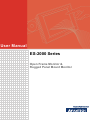
User Manual ES-2000 Series Open Frame Monitor & Rugged Panel Mount Monitor Copyright The documentation and the software included with this product are copyrighted 2006 by Advantech Co., Ltd. All rights are reserved. Advantech Co., Ltd. reserves the right to make improvements in the products described in this manual at any time without notice. No part of this manual may be reproduced, copied, translated or transmitted in any form or by any means without the prior written permission of Advantech Co., Ltd. Information provided in this manual is intended to be accurate and reliable. However, Advantech Co., Ltd. assumes no responsibility for its use, nor for any infringements of the rights of third parties, which may result from its use. Acknowledgements Intel and Pentium are trademarks of Intel Corporation. Microsoft Windows and MS-DOS are registered trademarks of Microsoft Corp. All other product names or trademarks are properties of their respective owners. Product Warranty (1 year) Advantech warrants to you, the original purchaser, that each of its products will be free from defects in materials and workmanship for one year from the date of purchase. This warranty does not apply to any products which have been repaired or altered by persons other than repair personnel authorized by Advantech, or which have been subject to misuse, abuse, accident or improper installation. Advantech assumes no liability under the terms of this warranty as a consequence of such events. Because of Advantech’s high quality-control standards and rigorous testing, most of our customers never need to use our repair service. If an Advantech product is defective, it will be repaired or replaced at no charge during the warranty period. For outof-warranty repairs, you will be billed according to the cost of replacement materials, service time and freight. Please consult your dealer for more details. If you think you have a defective product, follow these steps: 1. Collect all the information about the problem encountered. (For example, CPU speed, Advantech products used, other hardware and software used, etc.) Note anything abnormal and list any onscreen messages you get when the problem occurs. 2. Call your dealer and describe the problem. Please have your manual, product, and any helpful information readily available. 3. If your product is diagnosed as defective, obtain an RMA (return merchandize authorization) number from your dealer. This allows us to process your return more quickly. 4. Carefully pack the defective product, a fully-completed Repair and Replacement Order Card and a photocopy proof of purchase date (such as your sales receipt) in a shippable container. A product returned without proof of the purchase date is not eligible for warranty service. 5. Write the RMA number visibly on the outside of the package and ship it prepaid to your dealer. ES-2000 Series User Manual Part No. 2008211000 Edition 1 Printed in Taiwan November 2007 ii Declaration of Conformity CE This product has passed the CE test for environmental specifications when shielded cables are used for external wiring. We recommend the use of shielded cables. This kind of cable is available from Advantech. Please contact your local supplier for ordering information. CE This product has passed the CE test for environmental specifications. Test conditions for passing included the equipment being operated within an industrial enclosure. In order to protect the product from being damaged by ESD (Electrostatic Discharge) and EMI leakage, we strongly recommend the use of CE-compliant industrial enclosure products. FCC Class A Note: This equipment has been tested and found to comply with the limits for a Class A digital device, pursuant to part 15 of the FCC Rules. These limits are designed to provide reasonable protection against harmful interference when the equipment is operated in a commercial environment. This equipment generates, uses, and can radiate radio frequency energy and, if not installed and used in accordance with the instruction manual, may cause harmful interference to radio communications. Operation of this equipment in a residential area is likely to cause harmful interference in which case the user will be required to correct the interference at his own expense. FCC Class B Note: This equipment has been tested and found to comply with the limits for a Class B digital device, pursuant to part 15 of the FCC Rules. These limits are designed to provide reasonable protection against harmful interference in a residential installation. This equipment generates, uses and can radiate radio frequency energy and, if not installed and used in accordance with the instructions, may cause harmful interference to radio communications. However, there is no guarantee that interference will not occur in a particular installation. If this equipment does cause harmful interference to radio or television reception, which can be determined by turning the equipment off and on, the user is encouraged to try to correct the interference by one or more of the following measures: Reorient or relocate the receiving antenna. Increase the separation between the equipment and receiver. Connect the equipment into an outlet on a circuit different from that to which the receiver is connected. Consult the dealer or an experienced radio/TV technician for help. FM This equipment has passed the FM certification. According to the National Fire Protection Association, work sites are classified into different classes, divisions and groups, based on hazard considerations. This equipment is compliant with the specifications of Class I, Division 2, Groups A, B, C and D indoor hazards. iii ES-2000 Series User Manual Technical Support and Assistance 1. 2. Visit the Advantech web site at www.advantech.com/support where you can find the latest information about the product. Contact your distributor, sales representative, or Advantech's customer service center for technical support if you need additional assistance. Please have the following information ready before you call: – Product name and serial number – Description of your peripheral attachments – Description of your software (operating system, version, application software, etc.) – A complete description of the problem – The exact wording of any error messages Warnings, Cautions and Notes Warning! Warnings indicate conditions, which if not observed, can cause personal injury! Caution! Cautions are included to help you avoid damaging hardware or losing data. e.g. There is a danger of a new battery exploding if it is incorrectly installed. Do not attempt to recharge, force open, or heat the battery. Replace the battery only with the same or equivalent type recommended by the manufacturer. Discard used batteries according to the manufacturer's instructions. Note! Notes provide optional additional information. Document Feedback To assist us in making improvements to this manual, we would welcome comments and constructive criticism. Please send all such - in writing to: [email protected] Packing List Before setting up the system, check that the items listed below are included and in good condition. If any item does not accord with the table, please contact your dealer immediately. Item XXXXXXXX Box XXXXXXXXX ES-2000 Series User Manual iv Safety Instructions 1. 2. 3. 4. 5. 6. 7. 8. 9. 10. 11. 12. 13. 14. 15. Disconnect this equipment from AC outlet before cleaning. Do not use liquid or spray detergents for cleaning. For pluggable equipment, the power outlet shall be installed near the equipment and shall be easily accessible. To prevent the risk of fire or shock hazards, do not expose this product to rain or moisture. Please do not open or disassemble the products as this may cause electric shock. Put this equipment on a reliable surface during installation. Dropping it or letting it fall could cause damage. Do not leave this equipment in an environment unconditioned where the storage temperature under -20 C (-4º F) or above 60º C (140º F), it may damage the equipment. The openings on the enclosure are for air convection hence protects the equipment from overheating. DO NOT COVER THE OPENINGS. Make sure the voltage of the power source is correct before connecting the equipment to the power outlet. Place the power cord such a way that people can not step on it. Do not place anything over the power cord. The voltage and current rating of the cord should be greater than the voltage and current rating marked on the product. All cautions and warnings on the equipment should be noted. If the equipment is not used for long time, disconnect it from the power source to avoid being damaged by transient over-voltage. Never pour any liquid into ventilation openings. This could cause fire or electrical shock. Never open the equipment. For safety reasons, the equipment should be opened only by qualified service personnel. If any of the following situations arises, get the equipment checked by service personnel: – The power cord or plug is damaged. – Liquid has penetrated into the equipment. – The equipment has been exposed to moisture. – The equipment does not work well, or you cannot get it to work according to the user's manual. – The equipment has been dropped and damaged. – The equipment has obvious signs of breakage. – The equipment exhibits a distinct change in performance. This device complies with Part 15 of the FCC rules. Operation is subject to the following two conditions: – This device may not cause harmful interference, and – This device must accept any interference received, including interference that may cause undesired operation. Caution! 1. 2. Always completely disconnect the power cord from the chassis whenever working with hardware. Do not make connections while power is on. Sensitive electronic components can be damaged by sudden power surges. Any unverified component may cause unexpected damage. To ensure correct installation, please always use components (ex. screws) provided with the accessory box. v ES-2000 Series User Manual Safety Precaution - Static Electricity Follow these simple precautions to protect yourself from harm and the products from damage. To avoid electrical shock, always disconnect the power from your PC chassis before you work on it. Don't touch any components on the CPU card or other cards while the PC is on. Disconnect power before making any configuration changes. The sudden rush of power as you connect a jumper or install a card may damage sensitive electronic components. ES-2000 Series User Manual vi Contents Chapter Chapter 1 Introduction..........................................1 1.1 1.2 1.3 1.4 ES-2000 Series Introduction ..................................................................... 2 ES-2000 Series Features......................................................................... 2 Application Scenarios: Self Services Applications .................................... 2 ES-2000 Series Naming Rule & Anatomy................................................. 3 1.4.1 Naming rule................................................................................... 3 1.4.2 ES-2000 series anatomy............................................................... 3 Figure 1.1 ES-2100 Open Frame ................................................ 3 Figure 1.2 ES-2200 Rugged Panel Mount Monitor...................... 4 2 Specifications ......................................5 2.1 2.2 Specifications ............................................................................................ 6 Detailed Specifications.............................................................................. 7 Table 2.1: ES-2106 / ES-2206..................................................... 7 Table 2.2: ES-2106 / ES-2206..................................................... 7 Table 2.3: ES-2108 / ES-2208..................................................... 8 Table 2.4: ES-2108 / ES-2208..................................................... 8 Table 2.5: ES-2110 / ES-2210..................................................... 9 Table 2.6: ES-2110 / ES-2210..................................................... 9 Table 2.7: ES-2112 / ES-2212................................................... 10 Table 2.8: ES-2112 / ES-2212................................................... 10 Table 2.9: ES-2115 / ES-2215................................................... 11 Table 2.10: ES-2115 / ES-2215................................................... 11 Table 2.11: ES-2117 / ES-2217................................................... 12 Table 2.12: ES-2117 / ES-2217................................................... 12 Table 2.13: ES-2119 / ES-2219................................................... 13 Table 2.14: ES-2119 / ES-2219................................................... 13 Dimensions ............................................................................................. 14 Figure 2.1 ES-2106 Dimensions................................................ 14 Figure 2.2 ES-2206 Dimensions................................................ 14 Figure 2.3 ES-2108 Dimensions................................................ 15 Figure 2.4 ES-2208 Dimensions................................................ 15 Figure 2.5 ES-2110 Dimensions................................................ 16 Figure 2.6 ES-2210 Dimensions................................................ 16 Figure 2.7 ES-2112 Dimensions................................................ 17 Figure 2.8 ES-2212 Dimensions................................................ 17 Figure 2.9 ES-2115 Dimensions................................................ 18 Figure 2.10ES-2215 Dimensions................................................ 18 Figure 2.11ES-2117 Dimensions................................................ 19 Figure 2.12ES-2217 Dimensions................................................ 19 Figure 2.13ES-2119 Dimensions................................................ 20 Figure 2.14ES-2219 Dimensions................................................ 20 Accessory Packing.................................................................................. 21 2.4.1 ES-2100 Series with Glass, VGA interface................................. 21 2.4.2 ES-2100 Series with Touch, VGA interface ................................ 21 2.4.3 ES-2100 Series with Touch, LVDS interface .............................. 21 2.4.4 ES-2200 Series with Touch, VGA interface ................................ 21 2.3 2.4 vii ES-2000 Series User Manual Chapter 3 System Set Up................................... 23 3.1 3.7 Mounting Kits .......................................................................................... 24 3.1.1 Standard mounting ..................................................................... 24 Figure 3.1 ES-2100 Open frame mounting bracket................... 24 Figure 3.2 Inserting screws ....................................................... 24 Figure 3.3 Front view of LCD and brackets ............................... 25 3.1.2 Alternate mounting...................................................................... 26 Figure 3.4 ES-2100 Rear mount with screws ............................ 26 Figure 3.5 Rear mount with clamps and screws........................ 26 Figure 3.6 Rear mount clamp .................................................... 27 Figure 3.7 ES-2200 rugged panel mount .................................. 27 Figure 3.8 Rubber clamps for rear mounting holes ................... 28 Connecting the Display ........................................................................... 29 Figure 3.9 ES-2100/2200 power adaptor connection ................ 29 Figure 3.10ES-2100/2200 series VGA interface ........................ 30 Figure 3.11ES-2100/2200 series LVDS interface....................... 30 Screen Resolution................................................................................... 31 Table 3.1: ES-2100 VGA interface: motherboard BIOS resolution setting....................................................................... 31 Table 3.2: ES-2100/2200 LVDS interface (if connected to Advantech ARK-338X series)............................................. 31 LVDS Pin Assignment............................................................................. 32 Figure 3.12LVDS Connector ...................................................... 32 Table 3.3: LVDS Pin Assignment .............................................. 32 LCD Power Jumper Setting (JP6)........................................................... 33 Figure 3.13LCD power jumper location ...................................... 33 Table 3.4: LCD Power Setting (JP6) ......................................... 33 OSD (On-Screen Display) Functions ...................................................... 34 Figure 3.14ES-2117 OSD board ................................................ 34 Figure 3.15Main OSD screen ..................................................... 34 3.6.1 Color ........................................................................................... 35 Figure 3.16RGB adjustments ..................................................... 35 3.6.2 Picture......................................................................................... 36 Figure 3.17Picture adjustments.................................................. 36 3.6.3 Function ...................................................................................... 37 Figure 3.18Function adjustments ............................................... 37 3.6.4 OSD Menu .................................................................................. 38 Figure 3.19OSD display adjustments ......................................... 38 3.6.5 Language.................................................................................... 39 Figure 3.20Language selection .................................................. 39 3.6.6 Misc ............................................................................................ 39 Figure 3.21Misc selections ......................................................... 39 Figure 3.22Signal source............................................................ 40 Figure 3.23Exit selection ............................................................ 40 Touch Drivers.......................................................................................... 41 Appendix A Troubleshooting................................ 43 A.1 A.2 A.3 Introduction ............................................................................................. 44 No image appears on screen.................................................................. 44 The image is incorrectly displayed, or the full screen image does not appear..................................................................................................... 44 The position of screen is not in the center .............................................. 44 Out of Range........................................................................................... 44 No Signal ................................................................................................ 44 Going to Sleep ........................................................................................ 44 3.2 3.3 3.4 3.5 3.6 A.4 A.5 A.6 A.7 ES-2000 Series User Manual viii Chapter 1 1 Introduction ES-2100 & ES-2200 series Series features Self-service applications Series naming rule Series anatomy 1.1 ES-2000 Series Introduction The Advantech ES-2000 series is a new type of Embedded Open Frame and Rugged Panel Mount Monitor, designed to meet the needs of customers who want quick and easy integrations for their solutions with Advantech Embedded Box Computers like ARK, DVS and DSA. Advantech offers two subcategories of the ES-2000 series: ES-2100 series (open frame display) and ES-2200 series (rugged panel mount display). 1.2 ES-2000 Series Features Full range of LCD size options: standard from 6.5" to 19" can be integrated with difference type of touch screen and tempered glass. E.g. Resistive, Capacitive, SAW and Infrared Vandal Proof Flexible & customizable face plates for easy re-engineering Versatile interface options: LVDS & VGA (DVI and S-Video support by project) Long time industrial components support Fully integrated with all Advantech Box computers and Embedded single boards and Industrial motherboards. Versatile sunlight readable and ultra high brightness options Wide operating temperature LCD options Industrial grade rugged aluminum front bezel design for ES-2200 series. 1.3 Application Scenarios: Self Services Applications KIOSK / POI machine Transportation machine Ticketing machine Financial ATM Entertainment / Gaming / Slot machine HMI (Human-Machine Interface) equipment controller monitor Public communication machine Public advertisement machine ES-2000 Series User Manual 2 1.4.1 Naming rule Chapter 1 1.4 ES-2000 Series Naming Rule & Anatomy Introduction 1.4.2 ES-2000 series anatomy Figure 1.1 ES-2100 Open Frame 3 ES-2000 Series User Manual Figure 1.2 ES-2200 Rugged Panel Mount Monitor ES-2000 Series User Manual 4 Chapter 2 Specifications Detailed specifications Dimensions Accessory packing 2 2.1 Specifications The ES-2000Series offers the following features and meets precise specifications. Unless otherwise noted, all the information listed below are subject to change without prior notification I/O Ports: either DB-15 pin (VGA) or DB-26 pin (LVDS) – a.) 15-pin D-sub (VGA), DC power input, RS232 port & USB port for touch, Power switch and OSD keys (Auto-tune, menu, decrease, increase). OSD control ' Keys: Auto-tune, menu, decrease and increase. Functions: Brightness, Contrast, Clock, Phase, Horizontal Position, vertical Position and Sharpness. – b.) DB-26 pin (LVDS), DC power input, dimming control Knob, panel on/off control button, RS232 port & USB port for touch. Display Input Signal: Analog RGB, 0.7 VP-P / 75 Ohm. Optional : LVDS (DB26pin) Power Input: [email protected]. External Power Adapter: Max Output 50W(for 6.5"~17") & 60W(for 19"), AC input voltage 100 ~ 240V, UL/CE/CCC/TUV/CB Safety Humidity: 5 ~ 95%@40, non-condensing Shock: 10G peak acceleration (11 ms duration) EMC Approved: CE, FCC ES-2000 Series User Manual 6 Table 2.1: ES-2106 / ES-2206 Display Standard Sunlight Readable Size 6.5” 6.5” Resolution (pixels) 640 x 480 VGA 640 x 480 VGA Number of Colors 16.2M 16.2M Viewing Angle (L/R/U/D) 70° / 70° / 60° / 60° 70° / 70° / 60° / 60° Brightness (nit) 500 600 Contrast Ratio 600 :1 600 :1 Response Time (ms) 25 25 Lamp of Life (hrs) 50,000 50,000 Long-term support Yes Yes Anti-reflection N/A V Table 2.2: ES-2106 / ES-2206 Touchscreen Type Analog Resistive Capacitive SAW Infrared Thickness 1.87mm 3.18mm N/A N/A Resolution continuous 1024 x 1024 N/A N/A Light Transmission over 80% 85% N/A N/A Controller Interface RS232/USB RS-232 N/A N/A Power Consumption +5V @ 20mA +5V @ 100mA N/A N/A Touch Lifetime 36 million hrs 225 million hrs N/A N/A Driver OS Support DOS, Linux, Mac, Windows 95/98/NT/ME/CE/2000/XP 7 ES-2000 Series User Manual Specifications Feature Chapter 2 2.2 Detailed Specifications Table 2.3: ES-2108 / ES-2208 Display Feature Standard Sunlight Readable Size 8.4” 8.4” Resolution (pixels) 800 x 600 SVGA 800 x 600 SVGA Number of Colors 262K 262K Viewing Angle (L/R/U/D) 60° / 60° / 60° / 40° 70° / 70° / 60° / 60° Brightness (nit) 450 450 Contrast Ratio 500 :1 500 :1 Response Time (ms) 35 35 Lamp of Life (hrs) 50,000 50,000 Long-term support Yes Yes Anti-reflection N/A Yes Table 2.4: ES-2108 / ES-2208 Touchscreen Type Analog Resistive Capacitive SAW Infrared Thickness 2.67mm 3.0mm 3.0mm N/A Resolution 4096 x 4096 1024 x 1024 4096 x 4096 N/A Light Transmission 80% 85% 92% N/A Controller Interface RS-232/USB RS-232 RS-232/USB N/A Power Consumption +5V @ 200mA +5V @ 100mA +5V @ 75mA N/A Touch Lifetime 35 million hrs 225 million hrs 50 million hrs N/A Driver OS Support DOS, Linux, Mac, Windows 95/98/NT/ME/CE/2000/XP ES-2000 Series User Manual 8 Display Standard Sunlight Readable Size 10.4” 10.4” Resolution (pixels) 800 x 600 SVGA 800 x 600 SVGA Number of Colors 262K 262K Viewing Angle (L/R/U/D) 60° / 60° / 35° / 65° 60° / 60° / 35° / 65° Brightness (nit) 230 / 400 600 Contrast Ratio 500 :1 500 :1 Response Time (ms) 35 25 Lamp of Life (hrs) 20,000 / 50,000 50,000 Long-term support Yes Yes Anti-reflection N/A Yes Table 2.6: ES-2110 / ES-2210 Touchscreen Type Analog Resistive Capacitive SAW Infrared Thickness 2.67mm 3.18mm 3.0mm 3.0mm Resolution 4096 x 4096 1024 x 1024 4096 x 4096 4096 x 4096 Light Transmission 80% 85% 92% 92% Controller Interface RS-232/USB RS-232 RS-232/USB RS-232/USB Power Consumption +5V @ 200mA +5V @ 100mA +5V @ 75mA +5V @ 150mA Touch Lifetime 35 million hrs 225 million hrs 50 million hrs MTBF 100,000 hrs Driver OS Support DOS, Linux, Mac, Windows 95/98/NT/ME/CE/2000/XP 9 ES-2000 Series User Manual Specifications Feature Chapter 2 Table 2.5: ES-2110 / ES-2210 Table 2.7: ES-2112 / ES-2212 Display Feature Standard Sunlight Readable Size 12.1” 12.1” Resolution (pixels) 800 x 600 SVGA/ 1024 x 768 XGA 800 x 600 SVGA Number of Colors 262K 262K Viewing Angle (L/R/U/D) 70° / 70° / 50° / 60°; 65° / 65° / 75° / 45° 70° / 70° / 50° / 60° Brightness (nit) 400 / 320 400 Contrast Ratio 500 :1 / 550 :1 500 :1 Response Time (ms) 35 / 6 35 Lamp Life (hrs) 50,000 50,000 Long-term support Yes Yes Anti-reflection N/A Yes Table 2.8: ES-2112 / ES-2212 Touchscreen Type Analog Resistive Capacitive SAW Infrared Thickness 2.67mm 3.18mm 2.6mm 3.0mm Resolution 4096 x 4096 1024 x 1024 4096 x 4096 4096 x 4096 Light Transmission 80% 85% 92% 92% Controller Interface RS-232/USB RS-232 RS-232/USB RS-232/USB Power Consumption +5V @ 200mA +5V @ 100mA +5V @ 75mA +5V @ 150mA Touch Lifetime 35 million hrs 225 million hrs 50 million hrs MTBF 100,000 hrs Driver OS Support DOS, Linux, Mac, Windows 95/98/NT/ME/CE/2000/XP ES-2000 Series User Manual 10 Display Standard Sunlight Readable Size 15” 15” Resolution (pixels) 1024 x 768 XGA 1024 x 768 XGA Number of Colors 262K 262K Viewing Angle (L/R/U/D) 60° / 60° / 40° / 60° 70° / 70° / 70° / 50° Brightness (nit) 350 550 Contrast Ratio 500 :1 500 :1 Response Time (ms) 12 12 Lamp Life (hrs) 50,000 50,000 Long-term support Yes Yes Anti-reflection N/A Yes Table 2.10: ES-2115 / ES-2215 Touchscreen Type Analog Resistive Capacitive SAW Infrared Thickness 3.48mm 3.18mm 2.7mm 3.0mm Resolution 4096 x 4096 1024 x 1024 4096 x 4096 4096 x 4096 Light Transmission 80% 85% 92% 92% Controller Interface RS-232/USB RS-232 RS-232/USB RS-232/USB Power Consumption +5V @ 200mA +5V @ 100mA +5V @ 75mA +5V @ 150mA Touch Lifetime 35 million hrs 225 million hrs 50 million hrs MTBF 100,000 hrs Driver OS Support DOS, Linux, Mac, Windows 95/98/NT/ME/CE/2000/XP 11 ES-2000 Series User Manual Specifications Feature Chapter 2 Table 2.9: ES-2115 / ES-2215 Table 2.11: ES-2117 / ES-2217 Display Feature Standard Sunlight Readable Size 17” 17” Resolution (pixels) 1280 x 1024 SXGA 1280 x 1024 SXGA Number of Colors 16.2M 16.2M Viewing Angle (L/R/U/D) 70° / 70° / 70° / 60° 70° / 70° / 70° / 60° Brightness (nit) 300 450 Contrast Ratio 500 :1 500 :1 Response Time (ms) 8 8 Lamp Life (hrs) 50,000 50,000 Long-term support Yes Yes Anti-reflection N/A Yes Table 2.12: ES-2117 / ES-2217 Touchscreen Type Analog Resistive Capacitive SAW Infrared Thickness 3.48mm 3.18mm 2.7mm 3.0mm Resolution 4096 x 4096 1024 x 1024 4096 x 4096 4096 x 4096 Light Transmission 80% 85% 92% 92% Controller Interface RS-232/USB RS-232 RS-232/USB RS-232/USB Power Consumption +5V @ 200mA +5V @ 100mA +5V @ 75mA +5V @ 150mA Touch Lifetime 35 million hrs 225 million hrs 50 million hrs MTBF 100,000 hrs Driver OS Support DOS, Linux, Mac, Windows 95/98/NT/ME/CE/2000/XP ES-2000 Series User Manual 12 Display Standard Sunlight Readable Size 19” 19” Resolution (pixels) 1280 x 1024 SXGA 1280 x 1024 SXGA Number of Colors 16.7M 16.7M Viewing Angle (L/R/U/D) 89° / 89° / 89° / 89° 89° / 89° / 89° / 89° Brightness (nit) 300 550 Contrast Ratio 500 :1 500 :1 Response Time (ms) 8 8 Lamp Life (hrs) 50,000 50,000 Long-term support Yes Yes Anti-reflection N/A Yes Table 2.14: ES-2119 / ES-2219 Touchscreen Type Analog Resistive Capacitive SAW Infrared Thickness 3.48mm 3.18mm 2.7mm 3.0mm Resolution 4096 x 4096 1024 x 1024 4096 x 4096 4096 x 4096 Light Transmission 80% 85% 92% 92% Controller Interface RS-232/USB RS-232 RS-232/USB RS-232/USB Power Consumption +5V @ 200mA +5V @ 100mA +5V @ 75mA +5V @ 150mA Touch Lifetime 35 million hrs 225 million hrs 50 million hrs MTBF 100,000 hrs Driver OS Support DOS, Linux, Mac, Windows 95/98/NT/ME/CE/2000/XP 13 ES-2000 Series User Manual Specifications Feature Chapter 2 Table 2.13: ES-2119 / ES-2219 40.00 2.3 Dimensions 152.50 126.00 160.50 142.50 2.37 170.00 10.00 10.00 170.00 190.00 208.00 42.37 2.37 (Resistive T/S) 170.00 10.00 M3 TAP 102.80 CUT OUT 76.25 126.00 76.25 10.00 135.90 10.00 10.00 100.00 100.00 Figure 2.1 ES-2106 Dimensions 125.1 170.0 144.5 1.0 192.0 174.0 8.0 25.0 46.5 218.5 Figure 2.2 ES-2206 Dimensions ES-2000 Series User Manual 14 47.43 170.0 10.0 45.40 47.00 2.40 4.00 49.00 6.00 131.2 CUT OUT 174.1 10.0 132.0 10.0 Size Options 132.0 Figure 2.3 ES-2108 Dimensions 32.50 51.70 10.00 17.00 111.00 217.00 152.00 53.00 282.00 Figure 2.4 ES-2208 Dimensions 15 ES-2000 Series User Manual Specifications 100.0 126.0 100.0 37.0 M3 TAP 4.43 10.0 Chapter 2 47.0 26.0 135.0 115.0 (Resistive T/S) (Infra Red T/S) 49.0 46.0 4.0 7.0 75.0 28.79 (SAW T/S) 46.0 4.0 4.4 130.0 238.0 220.0 (Capactive T/S) 46.4 50.0 42.0 46.8 38.1 75.0 125.0 50.0 125.0 10.0 M3 TAP 10.0 CUT OUT 26.0 125.0 10.0 M3 TAP 125.0 10.0 CUT OUT 10.0 10.0 215.4 10.0 10.0 215.6 10.0 10.0 215.0 (For Mitsubishi panel) (For AUO-G104SN02 panel) (For AUO-G104SN03 panel) Figure 2.5 ES-2110 Dimensions 50.70 320.00 180.20 248.00 220.00 24.70 10.00 263.00 292.00 ES-2210 Figure 2.6 ES-2210 Dimensions ES-2000 Series User Manual 16 162.0 CUT OUT 26.0 130.0 10.0 162.7 125.0 50.0 125.0 10.0 M3 TAP 130.0 26.0 161.8 130.0 50.0 292.0 310.0 Chapter 2 15.0 49.36 53.5 120.0 120.0 75.0 28.79 115.5 251.0 269.0 115.5 3.36 38.1 75.0 337.0 355.0 (Capactive T/S) 120.0 15.0 120.0 M3 TAP 53.2 120.0 120.0 3.36 M3 TAP (SAW T/S) 50.0 4.0 (Infra Red T/S) 55.0 49.7 3.7 9.0 CUT OUT 115.5 115.5 CUT OUT 187.85 188.5 115.5 53.2 115.5 15.0 49.36 249.0 249.05 (For AUO panel) (For Mitsubishi panel) Figure 2.7 ES-2112 Dimensions 58.70 341.00 29.70 10.00 10.00 231.79 179.00 261.00 291.00 ES-2212 313.39 Figure 2.8 ES-2212 Dimensions 17 ES-2000 Series User Manual Specifications (Resistive T/S) 120.0 132.5 132.5 303.0 285.0 370.0 38.1 75.0 389.0 (Capacitive T/S) 69.5 54.0 55.0 240.0 M3 TAP 4.0 5.0 (SAW T/S) 55.73 5.73 189.5 132.5 213.3 265.0 307.4 190.5 (Infrared T/S) (Resistive T/S) Figure 2.9 ES-2115 Dimensions 398.00 58.70 12.00 29.70 10.00 42.50 285.00 203.00 229.00 314.00 199.00 344.00 370.00 ES-2215 Figure 2.10 ES-2215 Dimensions ES-2000 Series User Manual 59.0 9.0 147.5 15.0 120.0 75.0 70.5 28.79 15.0 50.0 21.0 18 56.24 120.1 120.8 28.8 75.0 100.0 120.0 38.1 402.1 25.2 120.8 120.1 120.8 25.2 5.24 56.24 5.19 56.19 3.7 54.7 7.0 58.0 80.0 120.0 274.4 80.0 25.2 420.1 25.2 341.9 Figure 2.11 ES-2117 Dimensions 430.50 59.50 31.50 10.00 320.40 248.20 347.80 352.00 402.10 ES-2217 Figure 2.12 ES-2217 Dimensions 19 ES-2000 Series User Manual Specifications 75.0 100.0 80.0 320.4 338.4 80.0 120.8 Chapter 2 5.24 Figure 2.13 ES-2119 Dimensions 474.8 31.7 60.9 391.8 75.0 100.0 251.2 364.4 28.8 10.0 38.1 75.0 100.0 382.4 446.4 Figure 2.14 ES-2219 Dimensions ES-2000 Series User Manual 20 2.4.1 ES-2100 Series with Glass, VGA interface VGA cable 1.8 meter 50W power adapter USA power code Open Frame U/D/L/R mounting bracket and screws Open Frame rear mounting clamper set (clamps and screws) Power Adapter DC jack plastic clamper & screw 2.4.2 ES-2100 Series with Touch, VGA interface VGA cable 1.8 meter RS232 cable 1.8 meter 50W power adapter USA power code Open Frame U/D/L/R mounting bracket and screws Open Frame rear mounting clamper set (clamps and screws) Power Adapter DC jack plastic clamper & screw 2.4.3 ES-2100 Series with Touch, LVDS interface DB26 LVDS cable 1.0 meter (with mounting screws) RS232 cable 1.8 meter 50W power adapter USA power code Open Frame U/D/L/R mounting bracket and screws Open Frame rear mounting clamper set (clamps and screws) Power Adapter DC jack plastic clamper & screw 2.4.4 ES-2200 Series with Touch, VGA interface VGA cable 1.8 meter RS232 cable 1.8 meter 50W power adapter USA power code Water sponge for panel mount use x 2 Open Frame rear mounting clamper set (clamps and screws) Power Adapter DC jack plastic clamper & screw Rubber clamper for rear mounting hole 21 ES-2000 Series User Manual Specifications Chapter 2 2.4 Accessory Packing Chapter 3 3 System Set Up Mounting kits Standard mounting Alternate mounting Connecting the display Screen resolution LVDS pin assignment LCD power jumper setting OSD functions Touch drivers 3.1 Mounting Kits Various mounting kits are available in which LCD panels may be suitabley framed and properly mounted according to the requirements of particular applications. Mounting kit options and basic installation instructions follow below. 3.1.1 Standard mounting Figure 3.1 ES-2100 Open frame mounting bracket 1. 2. 3. Place the ES-2100:LCD open frame face down on a flat surface and lay out all the four mounting brackets and screws, (See figure 3.1). Insert the screws and fasten them evenly all around the frame. Take care to ensure the assembly fits evenly and squarely around all four sides, (See figure 3.2). During final installation of frames and monitors to the kiosk /machine unit, it is recommend to place water-proof sealing strips between the frames and kiosk/ machine. Because rubber or sponge sealing strips may differ for each kiosk / machine design, Advantech does not offer it in the accessory box. Figure 3.2 Inserting screws ES-2000 Series User Manual 24 Chapter 3 System Set Up Figure 3.3 Front view of LCD and brackets Note! 1. 2. 3. Open frame brackets are precisely adjustable to match the kiosks and other mounting situations. It is possible to use any combination of the four left, right, up, down brackets; or, use only the left and right, or the up and down brackets with a rear mount of the open frame to the kiosk or other application. All four mounting brackets (U/D/L/R) and screws are included in the accessory box. The rear cover is drilled with the standard VESA mounting holes, 38.1mm x 38.1mm (all models), 75mm x 75mm (all models), 100mm x 100mm (15",17" & 19" models). 25 ES-2000 Series User Manual 3.1.2 Alternate mounting It is possible to mount the panel using either the mounting holes on the outside edge of the frame, or by using the optional clamps and screw holes. M3 TAP M3 TAP Figure 3.4 ES-2100 Rear mount with screws Figure 3.5 Rear mount with clamps and screws ES-2000 Series User Manual 26 Chapter 3 System Set Up Figure 3.6 Rear mount clamp WLL A ong a ter sp zelw Frnot be e IR S 0SER SE-2 20 Figure 3.7 ES-2200 rugged panel mount 27 ES-2000 Series User Manual Note! 1. 2. 3. Water proof sealing strips are included in the accessory box. Place the seals between the monitor and the kiosk/machine during the mounting process to repell water from coming inside the rear mounting brackets. Rear mounting clamps and screws are included in the accessory box. The rear cover is drilled with the standard VESA mounting holes, 38.1mm x 38.1mm (all models), 75mm x 75mm (all models), 100mm x 100mm (15",17" & 19" models). Figure 3.8 Rubber clamps for rear mounting holes ES-2000 Series User Manual 28 Follow the instructions below to connect the power to each display. 1. 2. Connect the power adaptor into the DC jack of ES-2100/2200series. Fasten the power cord clamp to the open frame rear cover, (as illustrated below). System Set Up ow P erlca mpe r Pow eradaptor 3. 4. Figure 3.9 ES-2100/2200 power adaptor connection If required, connect the RS-232 cable from the ES-2000 to the PC to access touchscreen controls. Alternatively, an optional USB cable, P/N: 1700002215; may be ordered to access touchscreen controls. 29 Chapter 3 3.2 Connecting the Display ES-2000 Series User Manual 5. Models in the ES-2100 range of open frame type mountings support VGA or LVDS connections, (as illustrated below). VGA CABLE Figure 3.10 ES-2100/2200 series VGA interface LVDS CABLE Figure 3.11 ES-2100/2200 series LVDS interface ES-2000 Series User Manual 30 The screen resolution must match same the LCD's resolution according to the overall size of the display. The larger the display size, the higher the resolution that is supported; select the most appropriate resolution for the monitor size according to the table below, otherwise the screen resolution may be out of range and not show the correct display. Chapter 3 3.3 Screen Resolution Table 3.1: ES-2100 VGA interface: motherboard BIOS resolution setting ES-2100/2200 Models 640 x 480 VGA ES-2106, ES-2206 800 x 600 SVGA ES-2108, ES-2208, ES-2110, ES-2210, ES-2112, 2212X-VSAE 1024 x 768 XGA ES-2112, 2212X-VXME, ES-2115, ES-2215 1280 x 1024 SXGA ES-2117, ES-2217, ES-2119, ES-2219 Note! Check the table above to determine the correct resolution for the appropriate ES-2100 series display. If any question remains unclear, contact the service center or sales representative for details. Table 3.2: ES-2100/2200 LVDS interface (if connected to Advantech ARK-338X series) BIOS Resolution ES-2100/2200 Models ARK JP6 Jump Setting 640 x 480 VGA ES-2106, ES-2206 3.3V 800 x 600 SVGA ES-2108, ES-2208, ES-2110, ES-2210, ES-2112, 2212XLSAE 3.3V 1024 x 768 XGA ES-2112, 2212X-LXME, ES2115, ES-2215 3.3V 1280 x 1024 SXGA ES-2117, ES-2217, ES-2119, ES-2219 5V (default) Note! 1. 2. The default resolution on the ARK-338X series is 1280 x 1024; therefore, the BIOS must be adjusted to the correct resolution according to the tables above. For example, the ES-2106 requires 640 x 480 VGA resolution; if the appropriate resolution is not selected in BIOS, the screen will be dark; a disconnect or offscreen notice may be displayed. The default JP6 setting on ARK-338X series is 5V. Therefore, for the ES-2117 and ES-2119 series, the rest of ES-2100 series must change the JP6 jump setting to 3.3V. 31 ES-2000 Series User Manual System Set Up BIOS Resolution 3.4 LVDS Pin Assignment The ES-2100/2200 open frame LVDS pin assignments are defined below. Figure 3.12 LVDS Connector Table 3.3: LVDS Pin Assignment Pin Signal Name Pin Signal name 1 LVDS_CLKBP 14 lLVDS_CLKBM 2 GND 15 LVDS_YAM0 3 LVDS_YAPO 16 lVDS_YAM1 4 LVDS_YAP1 17 LVDS_YAM2 5 LVDS_YAP2 18 LVDS_CLKAM 6 LVDS_CLKAP 19 GND 7 +3.3 OR +5V 20 +3.3 OR +5V 8 GND 21 LVDS_YAM3 9 LVDS_YAP3 22 LVDS_YBMO 10 LVDS_YBPO 23 LVDS_YBM1 11 LVDS_YBP1 24 LVDS_YBM2 12 LVDS_YBP2 25 LVDS_YBM3 13 LVDS_YBP3 26 GND ES-2000 Series User Manual 32 The ARK-3389 series of embedded box computer provides a jumper JP6 located onboard the internal PCM-9380 or PCM-9386 motherboard. The jumper specifies the signal power received by the LVDS LCD, which is either 5V or 3.3V. Whenever a new LVDS LCD panel display is connected, it is necessary to adjust the JP6 LCD power setting selection to match the power requirement of the LVDS LCD panel display. Chapter 3 3.5 LCD Power Jumper Setting (JP6) System Set Up Figure 3.13 LCD power jumper location . Table 3.4: LCD Power Setting (JP6) Setting Function, 1-2 +5V 2-3 +3.3V 33 ES-2000 Series User Manual 3.6 OSD (On-Screen Display) Functions The OSD of the ES-2117 display (1280 x 1024 resolution) was selected to illustrate the examples below: Figure 3.14 ES-2117 OSD board Figure 3.15 Main OSD screen ES-2000 Series User Manual 34 3.6.1.1 Contrast To adjust the contrast of the screen, press “UP arrow” to increase contrast, or “DOWN arrow” to decrease contrast. 3.6.1.2 Brightness To adjust the brightness of the screen, press “UP arrow” to increase brightness, or “DOWN arrow” to decrease brightness. 3.6.1.4 Color temperatue To adjust the color temperature of the screen, press “UP arrow” to increase color temperature, or “DOWN arrow” to decrease color temperature. 9300: Sets the monitor for the standard CIE 9300 color temperature coordinate. 6500: Sets the monitor for the standard CIE 6500 color temperature coordinate. 5500: Sets the monitor for the standard CIE 5500 color temperature coordinate. User: For precise individual configuration of color temperature on the display. 3.6.1.5 RGB color adjustments To adjust the RGB color output, press the “UP arrow” to increase the intensity of the selected color, or press the “DOWN arow” to decrease intensity of the selected color. Select “Exit” to return to the main menu. Figure 3.16 RGB adjustments 3.6.1.6 Exit Select “Exit” to return to the main menu. 35 ES-2000 Series User Manual System Set Up 3.6.1.3 Gamma To adjust the gamma of the screen, press “UP arrow” to increase gamma, or “DOWN arrow” to decrease gamma. Chapter 3 3.6.1 Color 3.6.2 Picture Figure 3.17 Picture adjustments 3.6.2.1 Position Vertical position To adjust the vertical position of the display on the screen, press “UP arrow” or the “DOWN arrow” to move the image up or down. Horizontal position To adjust the horizontal position of the display on the screen, press “UP arrow” or the “DOWN arrow” to move the image left or right. 3.6.2.2 Phase To adjust the phase of the display on the screen, press “UP arrow” or the “DOWN arrow.” Phase adjustment may be required to optimize the display quality. 3.6.2.3 Clock To adjust the width of the horizontal display, press the “UP arrow” or the “DOWN arrow.” 3.6.2.4 Sharpness To adjust the sharpness of the display, press the “UP arrow” or the “DOWN arrow.” 3.6.2.5 Exit Select “Exit” to return to the main menu. ES-2000 Series User Manual 36 Chapter 3 3.6.3 Function 3.6.3.1 Auto Adjust To automatically adjust the display, select Auto Adjust, “Yes.” 3.6.3.2 Auto Color To automatically adjust the color, select Auto Color, “Yes.” 3.6.3.3 Exit Select “Exit” to return to the main menu. 37 ES-2000 Series User Manual System Set Up Figure 3.18 Function adjustments 3.6.4 OSD Menu Figure 3.19 OSD display adjustments 3.6.4.1 OSD position Horizontal position To adjust the horizontal position of the OSD display on the screen, press “UP arrow” or the “DOWN arrow” to move the OSD image up or down. Vertical position To adjust the vertical position of the display on the screen, press “UP arrow” or the “DOWN arrow” to move the image up or down. 3.6.4.2 Translucent To adjust the translucence of the OSD, press “UP arrow” or the “DOWN arrow.” 3.6.4.3 Exit Select “Exit” to return to the main menu. ES-2000 Series User Manual 38 Chapter 3 3.6.5 Language 3.6.6 Misc Figure 3.21 Misc selections 3.6.6.1 Mode Select To select the display resolution, press “UP arrow” or the “DOWN arrow” to navigate between options. 3.6.6.2 Reset Select “Reset” to restore the factory default settings. 39 ES-2000 Series User Manual System Set Up Figure 3.20 Language selection To select the language on the OSD display, press “UP arrow” or the “DOWN arrow.” 3.6.6.3 Signal Source Figure 3.22 Signal source Select the signal source to display the current signal-out port. 3.6.6.4 Exit Select “Exit” to return to the main menu. Figure 3.23 Exit selection ES-2000 Series User Manual 40 The touch drivers for ES-2100 / 2200 series are available online at Advantech: http://www.advantech.com.tw/products/19-Open-Frame-Monitor/mod_124CE4Z.aspx Chapter 3 3.7 Touch Drivers System Set Up Note! For the Resistive Touch Driver, it is necessary to use the Advantech touch driver, which is available on the Advantech website. Do not download other drivers from other touchscreen vendors’ websites, to avoid the driver compatibility issues. 41 ES-2000 Series User Manual Appendix A Troubleshooting A A.1 Introduction If experiencing trouble with the monitor, or it fails to operate correctly, please refer to the following instructions before calling the Advantech service center. If unable to correct the faults using the instructions below, then please contact the distributor or the services/repair center. A.2 No image appears on screen Check to see that all the I/O and power connectors are installed correctly and connected. (Refer to 3.2, Connecting the Display). Make sure that none of the connectors are crooked, broken or loose. Make sure that the OSD power on the LED is turned on. Make sure that the brightness is not in the minimum. Make sure that the screen resolution is set to the correct setting for the type of LCD, and that the setting does not exceed the resolution specified for the particular model of LCD. (Refer to 3.3, Screen Resolution). A.3 The image is incorrectly displayed, or the full screen image does not appear Please make sure the screen resolution on the motherboard is correct. (Refer to 3.3, Screen Resolution). A.4 The position of screen is not in the center Adjust the H-position and V-position or Perform “Auto-Tune.” A.5 Out of Range When the message “Out of Range” appears onscreen, it indicates that the signal of the computer is not compatible with the LCD display; i.e. the resolution exceeds the specified resolution for the LCD. Adjust the BIOS setting to match the correct resolution. (Refer to 3.3, Screen Resolution). A.6 No Signal The display is powered on, but can neither receive nor display any signal from the computer. Check all power switches, power cables and VGA signal cables to ensure that all are connected correctly on both sides. A.7 Going to Sleep If the system goes to sleep, then the display has either been set to power-saving mode, or the display is experiencing a sudden signal disconnection problem. Check the BIOS system settings, and/or Windows configuration. Then check the connection of the power cable to the computer on both sides. ES-2000 Series User Manual 44 www.advantech.com Please verify specifications before quoting. This guide is intended for reference purposes only. All product specifications are subject to change without notice. No part of this publication may be reproduced in any form or by any means, electronic, photocopying, recording or otherwise, without prior written permission of the publisher. All brand and product names are trademarks or registered trademarks of their respective companies. © Advantech Co., Ltd. 2007