1
Chapter 2
Module Preparation and Installation
Display of Diagnostics
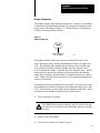
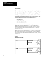
The module displays fault and alarm diagnostics. A battery low condition
is indicated by the non-blinking display of a single dot beneath the colon
in the center of the display (Figure 2.3). When the dot is first displayed,
24 hours of battery operation remain.
Figure 2.3
Battery Low Indicator
14:06
.
Battery Low Indicator
(Does Not Blink)
11218
The module indicates that power has been restored following a total
power failure (no battery backup) by blinking the display of eights in its
LCD. The blinking eights display indicates that previous calendar and
clock data have been lost, that the calendar and clock functions have
ceased, and that the module’s calendar and clock should be reset. When a
battery has been inserted in an unpowered clock module, the blinking
eights display indicates that the module’s calendar and clock are ready to
be set. Battery backup allows 100 hours of clock operation during power
failures or brownouts.
If the module detects an internal fault, the module’s clock will cease and a
non-blinking error number will appear in the right-most digit space of the
LCD. Error numbers are used during factory diagnosis and repair. In the
event that an error number is displayed, proceed as follows:
1. Power-down the I/O chassis.
CAUTION: Removing and inserting and I/O module when the
I/O chassis is powered can result in possible damage to module
circuitry.
2. Remove the clock module.
3. Press the reset switch (see “Reset Switch”).
23