1
User’s manual
OVERVIEW CONTROL MANAGER
Doc-3378-2
User level: service
DOC-3378-2, Current Version
Title:
Revision:
Date:
OVERVIEW CONTROL MANAGER DOC-3378-2
04
December 06
main issue
update
chapter 1
chapter 2
chapter 3
chapter 4
chapter 5
chapter 6
Chapter7
Chapter8
Chapter9
Chapter10
new:
corr.:
add.:
The corresponding chapters are new or completely revised.
Passages of the corresponding chapter were corrected; see modification bars.
Passages of the corresponding chapter were added; see modification bars.
This manual refers to following software versions
OverView Control Manager
Release 1.3
Document History
Modifications, which result in a new version, are indicated by a vertical bar.
New in release 1.3:
•
JRE installation is included in the setup
•
Extended error information
•
Support of localization
•
Advanced configuration paramaters
•
Visualization of the selected mini-module in the grid on the display wall (press ALT while selecting)
New in release 1.2:
•
Support for Linux
•
Support of small module view
•
Support of display walls comprising projection units with one and with two DVI interfaces
•
Test patterns for individual projection modules
•
Different password for Operator mode and Service mode
•
Start of the OCM client via the context menu of the icon in the system tray
Trademarks
Brand and product names mentioned in this manual may be trademarks, registered trademarks or copyrights of
their respective holders. All brand and product names mentioned in this manual serve as comments or examples
and are not to be understood as advertising for the products or their manufacturers.
Copyright © 2005, 2006 by BARCO
Die Weitergabe sowie die Vervielfältigung aller Unterlagen, die von uns überlassen werden, deren Verwertung
und Mitteilung ihres Inhaltes an Dritte ist nicht gestattet, soweit dies nicht ausdrücklich zugestanden ist.
Urheberrechte, insbesondere auch solche an Software, werden nur insoweit übertragen, als es für die Erreichung
des speziellen Vertragszwecks erforderlich ist. Zuwiderhandlungen können zu Schadensersatz verpflichten. Alle
Rechte aus der Erteilung eines Patents oder der Eintragung eines Gebrauchsmusters verbleiben bei uns.
Copyright © 2005, 2006 by BARCO
All rights reserved. No part of this document may be copied, reproduced or translated. It shall not otherwise be
recorded, transmitted or stored in a retrieval system without the prior written consent of BARCO.
Guarantee and Compensation
BARCO provides a guarantee relating to perfect manufacturing as part of the legally stipulated terms of
guarantee. On receipt, the purchaser must immediately inspect all delivered goods for damage incurred during
transport, as well as for material and manufacturing faults. BARCO must be informed immediately in writing of
any complaints.
The period of guarantee begins on the date of transfer of risks, in the case of special systems and software on
the date of commissioning, at the latest 30 days after the transfer of risks. In the event of justified notice of
complaint, BARCO can repair the fault or provide a replacement at its own discretion within an appropriate
period. If this measure proves to be impossible or unsuccessful, the purchaser can demand a reduction in the
purchase price or cancellation of the contract (redhibition). All other claims, in particular those relating to
compensation for direct or indirect damage, and also damage attributed to the operation of software as well as
to other services provided by BARCO, being a component of the system or independent services, will be deemed
invalid provided the damage is not proven to be attributed to the absence of properties guaranteed in writing or
due to the intent or gross negligence on the part of BARCO.
If the purchaser or a third party carries out modifications or repairs on good delivered by BARCO, or if the goods
are handled incorrectly, in particular if the systems are commissioned or operated incorrectly or if, after the
transfer of risks, the goods are subject to influences not agreed upon in the contract, all guarantee claims of the
purchaser will be rendered invalid. Not included in the guarantee coverage are system failures which are
attributed to programs or special electronic circuitry provided by the purchaser, e. g. interfaces. Normal wear as
well as normal maintenance are not subject to the guarantee provided by BARCO either.
The environmental conditions as well as the servicing and maintenance regulations specified in this manual must
be complied with by the customer.
Revision sheet
To:
•
BARCO Control Rooms GmbH
An der Rossweid 5, D-76229 Karlsruhe
Phone: +49-721-6201-0, Fax: +49-721-6201-298
E-mail: [email protected], Web: www.barcocontrolrooms.com
From:
Date:
Please correct the following points in this documentation (DOC-3378-2):
page
wrong
correct
Contents
1 Introduction........................................................................................................................................ 1-1
1.1 How this manual is organized ....................................................................................................................1-2
1.2 Styles and Symbols......................................................................................................................................1-3
2 Summary ............................................................................................................................................ 2-1
2.1 General.........................................................................................................................................................2-2
2.2 OVERVIEW D projection systems ....................................................................................................................2-2
2.3 OVERVIEW CONTROL MANAGER software ............................................................................................................2-2
3 Getting started................................................................................................................................... 3-3
3.1 OCM - for operators .....................................................................................................................................3-4
3.1.1 Monitoring a display wall...................................................................................................................3-5
3.1.2 Switching a display wall on/off.........................................................................................................3-8
3.1.3 Switching an individual projection module on or off........................................................................3-8
3.1.4 Check lamp status, determine the active lamp, change the active lamp .......................................3-9
3.1.5 Select the active source (firmware 3.x or higher only) ................................................................. 3-10
3.2 OCM - for service ...................................................................................................................................... 3-11
3.2.1 Brightness locking............................................................................................................................ 3-11
3.2.2 Lamp maintenance .......................................................................................................................... 3-15
3.2.3 Color and brightness adjustment (homogeneity).......................................................................... 3-19
3.2.4 Source selection and source switching mode (firmware 3.x or higher only)............................... 3-24
3.2.5 Control of Infra Red Control, message boxes and error boxes of the OSD ................................... 3-26
3.3 OCM – For Barco technicians .................................................................................................................... 3-27
3.3.1 Release and lock hot standby operation mode ............................................................................. 3-27
3.3.2 Lamp Driver...................................................................................................................................... 3-27
3.3.3 Change White Peaking .................................................................................................................... 3-28
3.3.4 Update lamp voltage ....................................................................................................................... 3-30
3.3.5 Update log level............................................................................................................................... 3-30
3.3.6 Re-calibrate brightness.................................................................................................................... 3-32
3.4 Known issues ...............................................................................................................................................3-1
4 Configuration of the projection modules.......................................................................................... 4-1
4.1 Projector address and cabling.....................................................................................................................4-2
4.2 Baud rate .....................................................................................................................................................4-3
5 OverView Control Manager on Linux platform ................................................................................. 5-1
5.1 System requirements ..................................................................................................................................5-2
5.2 Best practice ................................................................................................................................................5-2
5.3 Additional requirements .............................................................................................................................5-2
5.4 Installation of the OverView Control Manager on Linux............................................................................5-2
5.5 Start parameter for the OverView Control Manager client application ....................................................5-5
5.6 Additional commands for the OVD wall service.........................................................................................5-7
5.6.1 Check if the OVD wall service is running ...........................................................................................5-7
5.6.2 Disable / re-enable automatic startup of the OVD wall service ......................................................5-8
5.6.3 Start / stop / restart the OVD wall service .......................................................................................5-8
5.6.4 Check the log file ................................................................................................................................5-9
5.6.5 Uninstalling the OverView Control Manager .....................................................................................5-9
5.7 Configuration of the Barco RC Agent ....................................................................................................... 5-10
6 OverView Control Manager on Windows platform ........................................................................... 6-1
6.1 System requirements ..................................................................................................................................6-2
6.2 Best practice ................................................................................................................................................6-2
6.3 Used ports ....................................................................................................................................................6-2
6.4 Setup ............................................................................................................................................................6-3
6.4.1 Server installation...............................................................................................................................6-5
6.4.2 Client only installation........................................................................................................................6-7
6.5 Shortcuts created by the setup procedure .............................................................................................. 6-10
6.5.1 Configuration of the shortcut .......................................................................................................... 6-12
6.6 Icon created by the setup procedure ...................................................................................................... 6-12
6.7 OVD wall service....................................................................................................................................... 6-13
6.7.1 General............................................................................................................................................. 6-13
6.7.2 Start service ..................................................................................................................................... 6-13
6.7.3 Start OCM Client ............................................................................................................................... 6-14
6.7.4 Stop Service ..................................................................................................................................... 6-14
6.7.5 Restart Service ................................................................................................................................. 6-14
6.7.6 Configure Service ............................................................................................................................. 6-15
6.7.7 Open Console ................................................................................................................................... 6-17
6.7.8 About the service............................................................................................................................. 6-18
6.7.9 Exit.................................................................................................................................................... 6-18
7 OCM client application ....................................................................................................................... 7-1
7.1 Different operating systems .......................................................................................................................7-2
7.2 Launching the client application.................................................................................................................7-2
7.3 File menu .....................................................................................................................................................7-5
7.3.1 Authorization.......................................................................................................................................7-5
7.3.2 Refresh rate ........................................................................................................................................7-7
7.3.3 Wall Information .................................................................................................................................7-8
7.3.4 Wall Information – Wall Service ...................................................................................................... 7-10
7.3.5 Wall Information – Health Details ................................................................................................... 7-11
7.3.6 Exit.................................................................................................................................................... 7-14
7.4 Action menu ............................................................................................................................................. 7-15
7.4.1 Run Mode......................................................................................................................................... 7-16
7.4.2 Lamp Mode ...................................................................................................................................... 7-17
7.4.3 Source Selection (firmware 3.x only))............................................................................................ 7-18
7.4.4 Lamp Activation ............................................................................................................................... 7-19
7.4.5 Homogeneity ................................................................................................................................... 7-21
7.4.6 Test Patterns .................................................................................................................................... 7-29
7.4.7 On Screen Display ............................................................................................................................ 7-31
7.4.8 View Menu ....................................................................................................................................... 7-33
7.4.9 Module View .................................................................................................................................... 7-34
7.4.10 Lamp View ..................................................................................................................................... 7-35
7.4.11 Input Sources (firmware 3.x only) ................................................................................................ 7-36
7.4.12 Brightness Property Table ............................................................................................................. 7-37
7.4.13 Lamps property table .................................................................................................................... 7-40
7.4.14 Configuration property table......................................................................................................... 7-42
7.4.15 Help Menu...................................................................................................................................... 7-43
7.5 Context menu of the items in the grid.................................................................................................... 7-44
7.5.1 Module view .................................................................................................................................... 7-44
7.5.2 Lamp view........................................................................................................................................ 7-57
7.6 Tool bar ..................................................................................................................................................... 7-59
7.6.1 Brightness Locking........................................................................................................................... 7-60
8 Special configurations........................................................................................................................ 8-1
8.1 Localization ..................................................................................................................................................8-2
8.1.1 How to create language files .............................................................................................................8-3
8.1.2 How to facilitate the creation of language files................................................................................8-5
8.1.3 How to start the OverView Control Manager in a different language .............................................8-6
8.2 Large display wall........................................................................................................................................8-8
8.3 Projection units with one and with two DVI inputs (XGA resolution).................................................... 8-10
9 The OverView Control Manager configuration file ........................................................................... 9-1
10 Troubleshooting ............................................................................................................................. 10-1
10.1 Communication problems ...................................................................................................................... 10-2
10.2 DDP communication error...................................................................................................................... 10-3
10.3 Hot Line................................................................................................................................................... 10-5
1. Introduction
1 Introduction
This chapter explains the structure of the manual itself and the used typographic styles and symbols.
Barco – OverView Control Manager – DOC-3378-2 – user's manual – Revision 04 – December-2006 user mode: service ________________________________ 1-1
1. Introduction
1.1 How this manual is organized
This section explains the structure of the manual itself and the used typographic styles and symbols. Safety
information is provided concerning the operation of computer systems from BARCO.
•
Introduction
gives an overview about the used styles and symbols.
•
Summary
gives an overview about the functionality of the OVERVIEW CONTROL MANAGER software
•
Getting started
gives an overview about the functionality of the OCM client for the different run modes
•
Configuration of the projection modules
informs about the required settings and cabling of OverView D
•
Installation of OverView Control Manager on Linux platform
explains the installation of the OverView Control Manager on Linux systems, the start parameters and special
commands
•
Installation of OverView Control Manager on Windows platform
explains the installation of the OverView Control Manager on Windows systems, the start parameters and
shortcuts
•
OverView Control Manager Client
shows the different operating modes of the client and the corresponding user interfaces. This is independent
of the operating platform
•
Special configurations
explains how to display an OverView Control Manager grid for large display walls without scrollbars and
display wall employing projection units of the first and second generation
•
Trouble shooting
shows solutions in case a problem occurs
Chapters, pages, figures and tables are numbered separately. Chapters are indicated by a »point syntax«, e. g.
4.2.3, pages by a »dash syntax«, e. g. 2-1, as figures and tables are, e. g. figure 5-4.
Barco – OverView Control Manager – DOC-3378-2 – user's manual – Revision 04 – December-2006 user mode: service ________________________________ 1-2
1. Introduction
1.2 Styles and Symbols
The typographic styles and the symbols used in this document have the following meaning:
Bold
Labels, menus and buttons are printed in Bold font.
Condensed
Links to both other chapters of this manual and to sites in the Internet are printed
condensed. In the on-line version of this manual all hyperlinks appear teal.
Courier
Names of files and parts from programs are printed in the Courier font.
Courier bold
Inputs you are supposed to do from the keyboard are printed in Courier bold font.
The sheet icon indicates additional notes.
Next to this icon you find further information.
This icon marks tips.
Next to this icon you find important notes.
Barco – OverView Control Manager – DOC-3378-2 – user's manual – Revision 04 – December-2006 user mode: service ________________________________ 1-3
2. Summary
2 Summary
This chapter gives an overview about the functionality of the OVERVIEW CONTROL MANAGER software.
Barco – OverView Control Manager – DOC-3378-2 – user's manual – Revision 04 – December-2006 user mode: service ________________________________ 2-1
2. Summary
2.1 General
OVERVIEW CONTROL MANAGER is a software to monitor and control projection systems of the OVERVIEW D series via a
graphical and intuitive user interface.
2.2 OVERVIEW D projection systems
Projection systems of the OVERVIEW D series employ a projection unit based on DLP technology and a dual lamp
illumination unit.
The sophisticated projection systems allow to be adjusted in color, brightness, luminance, and to select the
operating mode (hot standby, cold standby) as well as the active lamp. Serial numbers of the projection unit and
the illumination unit as well as the runtime of the projection unit and the lamps are stored in the system and can
be accessed and modified.
OVERVIEW D offers an OnScreen Display, thus allowing controlling every individual projection system via an IR
Remote Control. By nature, the OSD is overlaying the applications on the display wall and does not allow
monitoring the system all the time. Moreover the OSD refers to a single unit and not to the entire display wall.
To monitor and control an OVERVIEW D display wall, use the OVERVIEW CONTROL MANAGER software!
2.3 OVERVIEW CONTROL MANAGER software
The OVERVIEW CONTROL MANAGER software is a Java application to monitor and control projection systems of the
OVERVIEW D series. Starting with Release 1.2, not only Windows platforms are supported, but also Linux and X.11.
Once installed, the OVERVIEW CONTROL MANAGER service (OVD wall service) runs on the PC after booting the systems.
Thus it is completely independent if and who logged in.
Depending on the actual requirements, the client software (OCM client) can be run in different modes allowing
different levels of interactions.
In the Operator mode, the user is informed about the status (health) of every projection system, he can switch
the entire display wall or a selected projection module on and off.
In case the projection module provide two DVI interfaces to display alternatively two sources (only for projection
systems with firmware 3.x or higher), he can select the active source.
In Service mode (advanced mode) in addition to these basic features the user can introduce new lamps into the
system (e.g. after a lamp failure and replacement of the lamp module), view and reset errors, change the
brightness target and view detailed data of system. If hot standby is enabled, the operating modus can be
selected. Color and luminance can be adjusted and multiple profiles can be created to store the current settings
and to reload them whenever wanted.
In case the projection modules provide two DVI interfaces to display alternatively two sources (firmware 3.x or
higher), in addition to the selection of the source also the switching mode (behavior on signal loss and reestablishing of the previous signal) can be selected.
For Barco technicians an extended Expert mode is provided to view and manage system data, perform
recalibration, disable over temperature protection and the dimmer, change the white peaking factor, release hot
standby operation mode and to introduce the actual lamp driver into the system when taking into operation a
display wall for the first time or after the entire wall has been upgraded with a new lamp driver.
Authorization to modify and manage system data is granted after entering the correct password (independent
passwords to access the Service mode and the Operator mode).
The following chapters might give you an idea about the capabilities of OVERVIEW CONTROL MANAGER software. For
further information please refer to the description of the user interface in chapter 7.
Barco – OverView Control Manager – DOC-3378-2 – user's manual – Revision 04 – December-2006 user mode: service ________________________________ 2-2
3. Getting started
3 Getting started
Barco – OverView Control Manager – DOC-3378-2 – user's manual – Revision 04 – December-2006 user mode: service ________________________________ 3-3
3. Getting started
3.1 OCM - for operators
To be able to operate the OCM client, first of all authorization has to be given: Select
File|Authorization and enter the correct password. Subsequently the commands and
buttons will be enabled. (In case the password has already been entered as start
parameter in the short cut, you will have enabled menus and buttons from start.).
In the operator mode, the OCM allows to monitor the health of a display wall, to switch the entire display wall or
individual projection modules on or off.
The OVERVIEW D projection systems employ a dual lamp illumination system with a top lamp and a bottom lamp.
One of these lamps is the active lamp to illuminate the optics, the other one is the backup lamp (fall back in case
of a lamp failure).
The operator can check which lamp is the active one, and he may also switch the active lamp.
In case the projection modules provide two DVI interfaces to connect two sources, he can also switch between
these sources (only available with firmware 3.x or higher).
The respective actions can be selected in the Action menu. If selected, they will be executed on all projection
modules of the display wall.
In addition, the OCM client offers different views. These views are selected in the View menu. The Module View
shows the representatives of the display wall in a grid, in the Lamp View a further refinement is made: each cell
displays lamp top and lamp bottom.
In case the projection systems support two DVI inputs, Source Selection shows the active source.
By means of the context menu when right-clicking one of the items in the grid a single projection module can be
addressed and switched.
Barco – OverView Control Manager – DOC-3378-2 – user's manual – Revision 04 – December-2006 user mode: service ________________________________ 3-4
3. Getting started
3.1.1 Monitoring a display wall
When monitoring a display wall, the main important information is about the health of the systems: Does
everything work as expected? If not – what's the problem?
The OVERVIEW CONTROL MANAGER provides a health icon in the status bar which indicates the health of the display
wall. In addition, the individual health of a projection module and the both lamps are visualized in the grid. If a
problem occurs, detailed information is given on a dedicated dialog tab.
At a glance, the status bar and the grid provide information about the health of the
system. To learn how to read it, cf. Wall Information – Health Details
Details of the problem can be found on the dialog File|Wall information:.
To open this dialog, there are three possibilities:
•
Double click on the yellow icon in the status bar.
•
Double click on the yellow icon in the gird.
•
Select the menu command File|Wall information.
Barco – OverView Control Manager – DOC-3378-2 – user's manual – Revision 04 – December-2006 user mode: service ________________________________ 3-5
3. Getting started
On the Health Details tab, the tool tip texts (move the mouse slowly of ther information
about the problem) offers a solution.
However, these solutions require probably to run the OCM client in service mode.
Barco – OverView Control Manager – DOC-3378-2 – user's manual – Revision 04 – December-2006 user mode: service ________________________________ 3-6
3. Getting started
As you can also see, the brightness level is indicated by different gray level:
if all representatives of the projection modules in the grid have the same gray level, the display wall features
homogeneous brightness. In case the gray of the cells are different, you can see which cubes are darker (in the
example, these are the cubes A2, B2, B3). Besides you can use File|Wall Information|Health Details to find out
how much the brightness differs.
Barco – OverView Control Manager – DOC-3378-2 – user's manual – Revision 04 – December-2006 user mode: service ________________________________ 3-7
3. Getting started
3.1.2 Switching a display wall on/off
The OVERVIEW CONTROL MANAGER enables to switch the entire display wall on/off at a simple mouse click.
It goes without saying, that it is also possible to switch a single projection module on/off.
3.1.3 Switching an individual projection module on or off
In the grid, clicking on a cell will open the context menu with the command to switch the projection module on
or off.
Barco – OverView Control Manager – DOC-3378-2 – user's manual – Revision 04 – December-2006 user mode: service ________________________________ 3-8
3. Getting started
3.1.4 Check lamp status, determine the active lamp, change the active lamp
Projection systems of the OVERVIEW D series are dual lamp systems. One lamp is active; the other one is the
backup lamp. In case of a lamp failure, the backup lamp becomes the active lamp. However it might be desired
to change the active lamp deliberately.
The lamp view allows seeing which lamp is running and which one is in (cold or hot) standby. The context menu
allows activating the backup lamp. In case of a lamp failure, the broken lamp is indicated by a red dot.
Barco – OverView Control Manager – DOC-3378-2 – user's manual – Revision 04 – December-2006 user mode: service ________________________________ 3-9
3. Getting started
3.1.5 Select the active source (firmware 3.x or higher only)
In case the projection modules provides two DVI interfaces to connect two sources, the active input can be
selected for all projection modules using the command Action|Source Selection.
Of course it can also be checked if a source is connected: Select View|Input sources to show input 1 and input 2
as rectangles in the grid, the left rectangle refers to input 1, the right one to input 2. In case a source is
connected, there is a green dot within the rectangle. A missing source is indicated with a red dot.
The rectangle of the active source has got a bold black border.
To change the active source for an individual projection module, use the context menu
.
Please refer also to the reference section, chapter 7.
Barco – OverView Control Manager – DOC-3378-2 – user's manual – Revision 04 – December-2006 user mode: service ______________________________ 3-10
3. Getting started
3.2 OCM - for service
In this chapter only the additional functionalities are explained. Of course all commands and functions of the
Operator mode are also available.
3.2.1 Brightness locking
OVERVIEW D projection modules are designed with the possibility of brightness regulation: a direct illumination
sensor (DIS) measures the light output.
By means of an optical dimmer the light output of a lamp can be controlled. The dimmer can be set between the
maximum value (all light of the lamp is coupled into the light rode) and its minimum value (40% of the entire
light output).
Thus the light output can be set to and compared with a given target.
Setting all projection modules of the entire display wall to the same target results in a display wall featuring
homogeneous brightness distribution.
Of course this brightness target has to be achieved by all active lamps.
In case the active lamp changes or in case of lamp replacement this lamp may no longer fit into this target.
Also lamp aging processes might result in lamps no longer adjustable to this target.
Then of course the brightness distribution of the display wall will no longer be homogeneous.
That's why the OVERVIEW CONTROL MANAGER offers Brightness locking.
Click on the Brightness locking button of the toolbar (second left button, see also tool tips). The brightness
dialog pops up. When the OCM is started and the Brightness Locking dialog is opened the first time, it will show
Fixed in case the display wall has a common brightness target (all projection modules set to the same target).
In case the projection modules differ in brightness target, the dialog will come up showing Disabled.
Barco – OverView Control Manager – DOC-3378-2 – user's manual – Revision 04 – December-2006 user mode: service ______________________________ 3-11
3. Getting started
The minimum value and the maximum value refers to the currently active lamps only!
Since the display wall shall feature a homogeneous brightness, homogeneity can only be achieved in the range
defined by the maximum light output of the darkest lamp and the minimum output of the brightest lamp.
The display wall can be run at maximized brightness (determined by the darkest lamp), minimized brightness
(determined by the brightest lamp) or at a fixed brightness target (between the maximum value and the
minimum value).
Next to the option the respective brightness values (lx) are indicated.
Option
Brightness target
Disabled
In case the projection systems of a display wall do not have a common brightness target, the
dialog opens with Disabled selected.
Maximized
The brightness target of the display wall is always the maximum value of the darkest lamp.
Minimized
The brightness target of the display wall is always the minimum of the brightest lamp
Fixed
Use the slider bar to define the brightness target.
This might be recommended in case it is only one lamp which e.g. forces the max. value
down.
In case all projection systems of a display wall have the same brightness target, the dialog
opens with Fixed selected. (The value then corresponds to the value of the brightness target)
Whereas the brightness mode Maximized and the brightness mode Minimized are dynamic
targets (in case of lamp aging the target will be adjusted automatically) represents the
brightness mode Fixed a static target which might no longer be reached in case the lamps
show reduced brightness due to aging processes..
The brightness mode is indicated in the status bar.
The last applied brightness mode and the brightness target value is memorized and restored properly when the
wall service is restarted.
Barco – OverView Control Manager – DOC-3378-2 – user's manual – Revision 04 – December-2006 user mode: service ______________________________ 3-12
3. Getting started
When changing the value for Fixed, changes will be applied to the display wall as soon as the slider bar has
been released.
If Fixed is selected, and a value is set which is above the value indicated as the max. brightness or below the
value indicated for the minimal brightness, the display wall cannot be adjusted to feature homogeneous
brightness. The representative of the cubes in the grid show different gray color to indicate the different
brightness level of the cubes.
The health status will then indicate a minor problem (yellow). Use File|Wall Information|Health Details to view
the distance of the target of those projector which cannot be adjusted to the target.
Barco – OverView Control Manager – DOC-3378-2 – user's manual – Revision 04 – December-2006 user mode: service ______________________________ 3-13
3. Getting started
Please keep in mind that brightness also influences the color adjustment. In case the
brightness locking mode is e.g. set to Maximum, and the brightness shifts due to aging
processes, also the color will shift.
Barco – OverView Control Manager – DOC-3378-2 – user's manual – Revision 04 – December-2006 user mode: service ______________________________ 3-14
3. Getting started
3.2.2 Lamp maintenance
The OCM client allows checking and viewing all relevant lamp data:
•
runtime and serial number
•
minimum and maximum brightness (dimmer position at 40% or at 100% open, respectively).
•
operation mode
•
brightness correction factor
All lamp relevant values can be viewed in the lamp property table.
By means of this table, the darkest lamps can easily be identified: click on the column header Max to sort the
lamps at the criteria of max. brightness.
Barco – OverView Control Manager – DOC-3378-2 – user's manual – Revision 04 – December-2006 user mode: service ______________________________ 3-15
3. Getting started
As you can see, B3 bottom is active and has a max. of only 172 whereas B3 top has a max.
of 214.
So you might want to change the active lamp in B3 for a brighter setting of the display
wall.
By means of this property table you can also decide if you want to extra replace some lamps, e.g. in case it is a
very old lamp (sort criteria: Runtime) or a very dark on (sort criteria: Max.).
In the grid you also see when a lamp fails: it is indicated with a red dot.
Whenever a lamp fails, before replacing it, retry to ignite it again!
To do this, the OCM client offers the command Retry after fail in the context menu of the
failed lamp in lamp view.
When a lamp failure occurs redundancy is no longer given!
If the command "Retry after fail" don't ignite the lamp, it is recommended to immediately replace the lamp to
re-establish redundancy.
Barco – OverView Control Manager – DOC-3378-2 – user's manual – Revision 04 – December-2006 user mode: service ______________________________ 3-16
3. Getting started
The command Retry after fail resets the error bit and tries again to ignite the lamp.
It is often due to a temporary change in voltage that the lamp fails. Therefore it is always worth to retry it!
If it is a relatively new lamp (check runtime!) you might want to try it again later.
In case you decide to replace the lamp, after the failure of the Retry after fail command, replace the lamp as
described in the user's manual of the projection system.
After the new lamp has been inserted, reset the error bit by pressing on the ON/RES switch on the rear side of
the projection module.
Since it is a new lamp, the OCM does not know its brightness, its serial number etc.
Therefore it is recommended to "introduce it to the OCM": select the new lamp to be the
active lamp! Then the OCM can measure its data. To get the best values, first run lamp
optimization!
Barco – OverView Control Manager – DOC-3378-2 – user's manual – Revision 04 – December-2006 user mode: service ______________________________ 3-17
3. Getting started
It is also recommended to select the command Optimize to align the position of the mirror for the new lamp.
This procedure can only be performed on the active lamp.
The display gets dark for about 3 seconds.
After this you might decide to keep the new lamp as active one or as backup lamp.
No matter whether it is the active lamp or the backup lamp: enter serial number and
runtime!
Barco – OverView Control Manager – DOC-3378-2 – user's manual – Revision 04 – December-2006 user mode: service ______________________________ 3-18
3. Getting started
3.2.3 Color and brightness adjustment (homogeneity)
After a display wall has been adjusted with CAST, all projection modules feature a homogeneous color and
brightness distribution.
When starting the OCM client for the first time, these settings will have to be saved as Service Adjustment to
enable a customized modification of color and/or brightness.
Service Adjustment is a special profile which, if applied, will always turn the display wall into the adjustment
status done by CAST, no matter which manual modifications had been made.
It is only after the Service Adjustment is saved that the buttons for modifying color and
brightness and brightness locking get enabled.
To save the Service Adjustment profile, select Action|Homogeneity|Save as Service Adjustment.
Subsequently the buttons on the toolbar are enabled and you are allowed to change color and brightness and to
save your modifications also as a profile to be able to re-load it on the wall.
To modify color and brightness, select the button Homogeneity improve on the tool bar (third left button, see
also tool tips) or select the respective command from the context menu in Module View.
Before the dialog to modify color and brightness opens, a white test pattern should be applied to the wall. Then
the Color&Brightness dialog pops up.
Barco – OverView Control Manager – DOC-3378-2 – user's manual – Revision 04 – December-2006 user mode: service ______________________________ 3-19
3. Getting started
3.2.3.1 Color adjustment
By means of the dialog, the current color impression of the selected projection module can be "entered" into the
color adjustment algorithm.
Example: If you consider the white of the projection module to be too green, indicate this "green-white" in the
color bitmap by double-clicking on the corresponding color. This will modify the color correction algorithm to shift
the color of the projection module towards white.
The indicated color coordinates of white as shown on top of the color bitmap will change accordingly.
In the bitmap, you have to indicate the actual color, not the desired color!
Please make sure that the color settings of your Windows desktop is set to 24bit!
In case the color you indicated is out of range, this is indicated on top of the color bitmap, and you cannot modify
the target:
Barco – OverView Control Manager – DOC-3378-2 – user's manual – Revision 04 – December-2006 user mode: service ______________________________ 3-20
3. Getting started
The OCM restricts color correction to a max. distance from the original factor white.
Therefore your selected color may be considered to be out of range.
When you are satisfied with the white of the selected projection module, click Close to exit the dialog.
You can also shift the color of the entire display wall by holding the CTRL key pressed
when double-clicking into the bitmap.
For special applications you might also want to shift the whitepoint towards e.g. red (color temperature of
3200K). This can also be done using the Color&Brightness dialog. Right-click in the bitmap to modify the target:
Barco – OverView Control Manager – DOC-3378-2 – user's manual – Revision 04 – December-2006 user mode: service ______________________________ 3-21
3. Getting started
Click also on the Help button to learn what and how:
All modifications can be saved as profile using the command Action|Homogeneity|Create New. This will display
a dialog to enter the name of the profile:
Barco – OverView Control Manager – DOC-3378-2 – user's manual – Revision 04 – December-2006 user mode: service ______________________________ 3-22
3. Getting started
If you don't save these modifications, they will be lost when shutting down the projector.
As long as the modifications are not saved, the Service Adjustment profile will show two asterix next to its
name to indicate that the current status of the display wall does not reflect the status of this profile:
All modifications saved as a profile can be re-applied to the display wall whenever wanted. This allows creating
e.g. a profile for an application with a gray background or a special profile for a special desktop layout.
Up to three profiles can be created. The related files are stored in the folder …\Barco OverView Control
Manager\Service\Adjustment\Name_of_display_wall on the computer running the OVD wall service.
The information stored in this file also include serial number of the projection unit and illumination unit. In case
discrepancies occur (e.g. a projection unit has been replaced) confirmation is required before the profile can be
loaded again.
If the discrepancies are too big, e.g. the entire display wall has been upgraded with new projection units, the
profile will not be loaded any more..
3.2.3.2 Brightness adjustment
The brightness values are typically measured in the center of the projection module. After the adjustment with
CAST all projection modules have the same brightness.
Due to inhomogeneities in brightness distribution within a single projection module there might however occur
brightness differences on the border of adjacent projection modules. So one of these projection modules should
be brighter (so that the border is brighter, too), the other one darker. But nonetheless both should be within the
target.
To solve this conflict the correction factor has been introduced. This factor allows to change the brightness in the
range of ±30% without changing the DIS value.
Use the slider bar on top of the Color&Brightness dialog to adjust the correction factor.
Of course this adjustment can also saved as or within a profile.
Color and brightness adjustment may also be required due to lamp aging or when a lamp
has been replaced and the new lamp no longer fits into the target.
Please see also Homogeneity .
Barco – OverView Control Manager – DOC-3378-2 – user's manual – Revision 04 – December-2006 user mode: service ______________________________ 3-23
3. Getting started
3.2.4 Source selection and source switching mode (firmware 3.x or higher only)
OVERVIEW D projection modules with firmware 3.x or higher feature two DVI interfaces to connect two sources. The
OCM client allows to check the sources, to select the active source and to define the switching mode.
It goes without saying that all of these functionalities can be applied to the entire display wall (menu
commands) or to an individual projection module (command in the context menu of the grid in Module view).
To view the sources, select View|Input sources.
The grid shows to rectangles, the left one represents source 1 (input 1), the right one represents source 2 (input
2). The selected switching mode is also indicated.
Green dots within the rectangles show that the sources are connected. A missing source is indicated by a red dot.
The currently active source is shown with a bold black border.
To switch the active source for all projection modules, select Action|Source Selection. The currently active source
is indicated by a black dot. To activate the other source, click its entry in this sub menu.
As you can see, this sub menu allows also to select the switching mode.
In Manual Mode, all source switching has to be done by user intervention. If the active source fails, and no user
intervention happens, the display shows the selected background image (e.g. color bars).
In Auto Preference Mode, the user selects its preferred source. This source is displayed until it fails. Then the
system automatically switches to the second sources.
In case the previous source is restored, the system will switch back to the previous source, since this is the
preferred one.
In Auto Switch mode the user selects the source to be displayed. This source is displayed until it fails. Then the
system automatically switches to the second sources. This source will be displayed no matter if source 1 is reestablished or not.
It is up to you to decide which mode to apply.
In case of a redundant controller, if source 1 fails, in both Auto modes the second source is
displayed.
In case of Auto Preference Mode, if the failed controller re-boots, at once this signal will
be displayed on the display wall. Worst case: nobody logs in, and the log-in window is
displayed for hours….
Just to give you an idea about the differences of the two modes Auto Preference Mode
and Auto Switch Mode.
Barco – OverView Control Manager – DOC-3378-2 – user's manual – Revision 04 – December-2006 user mode: service ______________________________ 3-24
3. Getting started
Let's assume source 1 and source 2 are connected, source 1 is the active source.
Then source 1 fails…. and is re-established later.
Source 1
Source 2
Preference
Manual mode
Auto Preference
Auto Switch
Selected source:
will remain source 1
during all
combinations!
Selected source:
will remain source 1
during all
combinations!
Selected source
(preference):
will toggle between
source 1 and source 2
source 1
source 1
source 1 <--> source 2
present
present
display source 1
display source 1
display source 1,
preference = source 1
gets disconnected
present
switch to background display source 2
display source 2,
preference = source 2
not connected
present
background
display source 2
display source 2,
preference = source 2
gets connected
present
switch to source1
switch to source1
display source 2,
preference = source 2
In Auto Switch mode, as soon as the source is switched, preference is also switched!
Barco – OverView Control Manager – DOC-3378-2 – user's manual – Revision 04 – December-2006 user mode: service ______________________________ 3-25
3. Getting started
3.2.5 Control of Infra Red Control, message boxes and error boxes of the OSD
OCM client in service mode grants full control over the message boxes and error boxes of the OSD. They can be
enabled and disabled for all projection modules by means of the commands Action|On Screen Display.
Also Infra red control can be enabled. This will however the projection module exclude from being controlled by
the OverView Control Manager.
For stability reasons and for optimization a projection module can EITHER be controlled by
the OCM, OR by Infrared Remote Control.
Selecting software control (OCM) disables IR Remote Control and vice versa.
Please refer also to the respective commands in the reference section, chapter 7.
Barco – OverView Control Manager – DOC-3378-2 – user's manual – Revision 04 – December-2006 user mode: service ______________________________ 3-26
3. Getting started
3.3 OCM – For Barco technicians
For customer support engineers the OVERVIEW CONTROL MANAGER offers additional commands to release the hot
standby operation mode, to introduce the actual lamp driver to a new display wall, to update lamp driver
information after an upgrade of the entire display wall, to change the white peaking factor, to measure the lamp
voltage , update the log level, re-calibrate lamps, disable overtemperature protection and to disable the optical
dimmer.
Authorization is given by entering the password of the Service mode.
3.3.1 Release and lock hot standby operation mode
To release and to lock the hot standby operation mode, after the selection of the respective command the
license key for the projection module A1 has to be entered.
Make sure that you inform BCD customer support center that hot standby has been
released. This information has to be added to the customer data!
3.3.2 Lamp Driver
The lamp driver information of a new projection module is set to Power Pack 120W (default).
When the display wall is set up, before taking it into operation, the actual lamp driver has to be introduced.
In case it is really Power Pack 120W, nothing has to be done. In case of Power Pack 100W, or Osram 200W the
lamp driver has to be corrected.
Select the command Action|Lamp driver and select the correct lamp driver for this display wall.
This command switches the lamp driver information of every projection module into the selected one.
Barco – OverView Control Manager – DOC-3378-2 – user's manual – Revision 04 – December-2006 user mode: service ______________________________ 3-27
3. Getting started
This command might only be selected if all projection modules of the entire display wall
have the same lamp driver! Never select this command without first having checked that
all illumination units employ the same lamp driver.
3.3.3 Change White Peaking
This command allows you to change the white peaking factor of all projection modules, the respective command
for a single projection module Is in the context menu of the grid in Module view:
Barco – OverView Control Manager – DOC-3378-2 – user's manual – Revision 04 – December-2006 user mode: service ______________________________ 3-28
3. Getting started
Changing the white peaking factor has impact on the color adjustment: a color adjustment
is only valid for the white peaking factor it has been created with. Handle with care!
Barco – OverView Control Manager – DOC-3378-2 – user's manual – Revision 04 – December-2006 user mode: service ______________________________ 3-29
3. Getting started
3.3.4 Update lamp voltage
Lamp voltage might be an indicator about the health of the lamp. Therefore it might be useful to monitor and
check it.
In the Lamp property table there is already a column foreseen to show the lamp voltages. However, their
measurement has to be triggered by means of the command Action|Expert Level|Update Lamp Voltage.
Please note that lamp voltage depends on the lamp driver!
As a rule of thumb we can say: the higher the lamp voltage, the higher the possibility that the lamp will fail
soon. However, the lamp voltage depends on the lamp driver, and also its measurement is not accurate enough
to give a clear message when a lamp will really fail.
3.3.5 Update log level
OVERVIEW CONTROL MANAGER provides a log console to supervise the system.
To display the OVD_WallService Console, select Open Console from the context menu of the OCM icon in the
system tray:
Subsequently the console window is displayed:
Barco – OverView Control Manager – DOC-3378-2 – user's manual – Revision 04 – December-2006 user mode: service ______________________________ 3-30
3. Getting started
The features which are supervised and logged can be modified by editing the file OVD_WallService_log4j. This
file is located in the folder …\Barco OverView Control Manager\Service on the workstation the OVD wall
service is running .
After updating this file, use the command Update Log Level to activate the modifications or restart the service.
Barco – OverView Control Manager – DOC-3378-2 – user's manual – Revision 04 – December-2006 user mode: service ______________________________ 3-31
3. Getting started
3.3.6 Re-calibrate brightness
Although re-calibrate is a command located in the context menu of the lamps in Lamp View, it should not be
performed for the selected lamp only, but for all lamps, active lamps and backup lamps, of the entire display
wall. This can only be skipped if the measurement device for re-calibration is about the same as the one used for
the initial calibration (probably done with CAST).
Re-calibration resets the brightness correction factor, and it requires that the lamp optimization procedure
has been run.
Then a properly calibrated lux meter has to be centered on the screen, the brightness value has to be measured
and noted.
Finally this measured value has to be entered in the dialog popping up after the command Re-Calibrate
Brightness has been selected:
Please refer also to the reference section, chapter 7.
Barco – OverView Control Manager – DOC-3378-2 – user's manual – Revision 04 – December-2006 user mode: service ______________________________ 3-32
3. Getting started
3.4 Known issues
If OVERVIEW CONTROL MANAGER service is running, to access the device control of APOLLO API the Barco OCM RC Agent
has to be enabled (Configure OverView Control Manager).
However, the OVERVIEW D projection modules can either be controlled by APOLLO or by the OCM. Therefore make
sure that in the Barco RC Agent OVD control is disabled.
The Barco RC Agent and the Barco OVD wall service shall not run simultaneously. To make
use o f device control in Apollo wall management software activate the Barco OCM RC
Agent.
In Apollo rel. 1.7 and earlier, in addition the read community has to be changed to
"ulcibp" and the write community to "acorb".
In Apollo rel. 1.8 or higher no changes of the read and write community are required.
Since the OVERVIEW CONTROL MANAGER disables IR remote control of the projection modules, in case the OCM
crashes, IR remote control of the projection modules has to be manually re-enabled, either by RS232 or by
clicking about 10 seconds on the ON/RES button on the rear side of the projection modules.
(In case the OCM is programmatically shut down, IR remote control will automatically be re-enabled!).
Minimum and maximum brightness of a lamp are not stored in a file. In case the OCM is shut down, after restart, all lamps have to be running at least once to enable the OCM to retrieve min. and max. brightness.
Barco – OverView Control Manager – DOC-3378-2 – user's manual – Revision 04 – December-2006 user mode: service ________________________________ 3-1
4. Configuration of the projection modules
4 Configuration of the projection modules
Barco – OverView Control Manager – DOC-3378-2 – user's manual – Revision 04 – December-2006 user mode: service ________________________________ 4-1
4. Configuration of the projection modules
4.1 Projector address and cabling
OVERVIEW CONTROL MANAGER 1.2 supports projection systems of the OVERVIEW D series with firmware version 2.22
(XGA, SXGA) and 3.4 (XGA, SXGA+). If required, first update the firmware (use "Serial Programmer").
Projection units with only one DVI interface require firmware version 2.x and must not be
updated to firmware version 3.x!
The individual projection systems have to be assigned a unique projector address and to be connected in an
RS232 chain.
It is mandatory that the projector address complies with the following rule:
Seen from front:
The most left projector of the most upper row has the projector address 1, the second left
projector of the most upper row the address two and so on, until all projectors of the most
upper row have got their address accordingly. Subsequently proceed with the second
upper row, also start with the most left projector.
The diagrams below show a display wall seen from front, the projector addresses and the two allowed ways of
remote control cabling!
COM1
COM1
1
9
17
25
2
10
18
26
3 4 5 6 7 8
11 12 13 14 15 16
19 20 21 22 23 24
27 28 29 30 31 32
1
9
17
25
2
10
18
26
3 4 5 6 7 8
11 12 13 14 15 16
19 20 21 22 23 24
27 28 29 30 31 32
COM1: the COM-interface of the PC running the OVERVIEW CONTROL MANAGER service!
With OverView DG and OverView DR chains with up to 32 projectors are supported, with
firmware 3.x chains up to 254 projectors are supported.
Release 1.0, release 1.1, and release 1.2 and release 1.3 of OVERVIEW CONTROL MANAGER do not
support multiple chains.
To assign a projector address, use the IR Remote Control Unit and activate the Service menu of the OSD (cf.
Installation manual of OverView D). In the Service menu, select Projector Address.
The projector address and the common RC5 address is displayed.
Projector addresses
Projector address
5
Common RC5 address
0
To change a value:
•
Move the cursor key to the respective field.
•
Enter the new value by means of the numeric keys of the IR Remote-Control.
Barco – OverView Control Manager – DOC-3378-2 – user's manual – Revision 04 – December-2006 user mode: service ________________________________ 4-2
4. Configuration of the projection modules
4.2 Baud rate
The baud rate depends on the firmware of the projectors.
Projectors with firmware 2.x require a baud rate of 9600.
Projectors with firmware 3.x require a baud rate of 115000.
Please make sure that the RS 232baudrate of the projection units are set to the correct value!
•
In the OSD, navigate to Brightness.
•
Enter the access code for the Service menu and press Enter
•
In the Service menu, select RS232 Baudrate
•
Make sure that 9600 is marked with a white dot in case of firmware 2.x or 115000 in case of firmware 3.x.
Firmware 2.x requires a baudrate of 9600!
Barco – OverView Control Manager – DOC-3378-2 – user's manual – Revision 04 – December-2006 user mode: service ________________________________ 4-3
5. OverView Control Manager on Linux platform
5 OverView Control Manager on Linux platform
Barco – OverView Control Manager – DOC-3378-2 – user's manual – Revision 04 – December-2006 user mode: service ________________________________ 5-1
5. OverView Control Manager on Linux platform
5.1 System requirements
Release 1.0 and Release 1.1 of OVERVIEW CONTROL MANAGER support Windows platforms only.
Starting with Release 1.2, also Linux is supported.
•
Minimum: PC with at least PIII, 400 MHz, 256 MB.
For server installation recommended: PIV, 2 GHz, 512 MB
For client installation recommended: PIII, 1 GHz, 512 MB
5.2 Best practice
It is recommended to first read the readme file located on the CD-ROM!
You have to get root to install OVERVIEW CONTROL MANAGER software.
5.3 Additional requirements
The installation procedure starts the vi editor to modify the configuration file. Make sure that the vi editor is
available on the system!
In addition the desktop resolution should be at least XGA (1024x768), and the color depth set to 24bit!
For color adjustment, a color bitmap is used. In case the color depth of the desktop is only
16 bit, the colors of this bitmap will never match the color impression of the projection
module thus making it impossible to adjust the projection modules in color!
5.4 Installation of the OverView Control Manager on Linux
You need to get root to install the software.
When installing OverView Control Manager, starting the installation will automatically deinstall any older version. Files which had been changed will not be removed, cf. Uninstalling
the OverView Control Manager.
OverView Control Manager will automatically install the required JRE.
On Linux system, always the Server and the Client software is installed. In case no Server
software is required, it can be deactivated by removing it from the autostart, cf. Disable / reenable automatic startup of the OVD wall service.
On a TransForm A X-Terminal you might first need to mount the CD by using the following
command:
mount /dev/cdrom /mnt/cdrom
•
The CD-ROM includes the required files to install OverView Control Manager on Linux::
install.sh
ocm-1.02-xxxx.i386.rpm
•
Change the directory to /mnt/cdrom
•
Open a console and get root
Barco – OverView Control Manager – DOC-3378-2 – user's manual – Revision 04 – December-2006 user mode: service ________________________________ 5-2
5. OverView Control Manager on Linux platform
•
Run the install script. It is located on the root directory of the CD-ROM. To run the script regardless to the set
file attributes, type the command
sh ./install.sh.
The following message is displayed.
To install OverView Control Manager, type Y (or y).
The default value is always indicated in brackets and will be applied if you simply press
ENTER.
In case of a previous installation of the OverView Control Manager, the customized configuration file
OVD_WallService-xml has been kept during the de-installation of the previous version (cf. Uninstalling the
OverView Control Manager) and been renamed to OVD_WallService.xml.rpmsave. The setup procedure asks if this
configuration file is to be used.
If the old wall configuration file is to be used, the installation procedure renames the file
OVD_WallService.xml.rpmsave to OVD_WallService.xml.
Setup continues. The file OVD_WallService.xml (either the default one installed by the rpm package, or the old
one of a previous configuration) is automatically opened by the vi Editor to allow changing the settings (as
already indicated at the beginning of the installation):
Carefully read the explanations given at the beginning of the file, and then scroll down to the section where the
configuration is specified.
Barco – OverView Control Manager – DOC-3378-2 – user's manual – Revision 04 – December-2006 user mode: service ________________________________ 5-3
5. OverView Control Manager on Linux platform
The configuration section includes the following settings:
Setting
description
Width
Number of columns of the display wall (horizontal cubes)
Height
Number of rows of the display wall (vertical cubes)
COM_port
COM Port OCM uses for communication, change to /dev/TTYS0 to use COM1
with Linux
Baudrate
Baud rate of RS232 communication, 9600 mandatory for firmware 2.x, for
firmware 3.x also higher baud rates are possible
Owner
Name of customer
Location
Name of location
Wallname
Friendly name of the display wall
ip_port
TCP/IP Port the OCM uses for communication, default port is 6063
Demo
Allows running the OCM in demo mode, e.g. simulating a display wall
Rc_agent
Indicates whether the Barco RC Agent shall also run.
In case the Barco RC Agent has been selected, it has also to be configured, cf.
Configuration of the Barco RC Agent
Passwd
Password of the Service (and Expert) mode, default is barco (all small!)
Passwd_operator
Password of the Operator mode, default is barco (all small!)
brightness_tolerance
Percentual brightness difference that must be reached before OCM indicates
that a projector did not reach a brightness target. Default value = 5.
poll_interval_hf
Polling intervall for frequently changing paramters, default value = 2
(seconds)
poll_interval_mf
Polling intervall for less frequently changing paramters, default value = 10
(seconds)
bl_check_interval
Period the brightness manager waits befween updates of the brightness
target, default value = 25 (seconds)
ddp_err_auto_restart
Only for SXGA resolution! If set to "1", a hotfix is activated to switch the
projection modules off and on again in case a ddp master/slave
communication occurs, cf. DDP communication error
Barco – OverView Control Manager – DOC-3378-2 – user's manual – Revision 04 – December-2006 user mode: service ________________________________ 5-4
5. OverView Control Manager on Linux platform
•
Type i to activate the insert mode of the vi editor.
•
Adjust the settings according the actual requirements.
•
Type :wq to save the adjusted settings and to exit the vi editor.
Setup asks if you want to start the OVD wall service:
Type Y to start the OVD wall service. Then you are asked if to start the OverView Control Manager Client:
As default, OVD wall service will always be started when booting the system.
If required, disable this behavior, cf. Disable / re-enable automatic startup of the OVD wall service.
Barco – OverView Control Manager – DOC-3378-2 – user's manual – Revision 04 – December-2006 user mode: service ________________________________ 5-5
5. OverView Control Manager on Linux platform
5.5 Start parameter for the OverView Control Manager client application
Starting the OCM client by typing Y during the setup procedure starts the OCM client in Service mode without
any start parameters (switches).
To customize the starting of the client application, type N, and then enter the start command including the
desired parameters manually.
The following lists comprises the parameters and switches to start OCM client:
Switch
default
description
-language
en
language for the client as digits ISO-639 code (en,de,ja,es), cf. Localization
if this parameter is specified it must be at the first position in the paramter list
-hostname
Localhost
Computer name or network address of the wall OVD wall service the client
connects to
-passwd
barco
Password to operate the OverView Control Manager (otherwise it starts readonly) Please mind: the password is case sensitive! The default password barco is
all small!
-ip_port
6063
Port the web service uses
-service
-refreshrate
-small
Starts the client application in service mode
5
Poll rate the OCM client asks the OVD wall service for information
Starts the OCM in small module view to display large display walls without the
need to use scrollbars
To start the OCM client manually including start parameters,
•
Change to the Client directory
•
Enter ./StartClient.sh –parameter1 –parameter2 – parameter3
Barco – OverView Control Manager – DOC-3378-2 – user's manual – Revision 04 – December-2006 user mode: service ________________________________ 5-6
5. OverView Control Manager on Linux platform
5.6 Additional commands for the OVD wall service
5.6.1 Check if the OVD wall service is running
As default, the OVD wall service is started when booting the system. To check if the service is running, use the
following command:
In case the wall service is running, the systems shows a message similar the one showed in the screenshot.
In case the wall service is not running, only the line including grep ovd_wallservice is displayed.
Barco – OverView Control Manager – DOC-3378-2 – user's manual – Revision 04 – December-2006 user mode: service ________________________________ 5-7
5. OverView Control Manager on Linux platform
5.6.2 Disable / re-enable automatic startup of the OVD wall service
On Linux systems, OverView Control Manager Release 1.2 is always installed completely
(server and client). If only the client is required, disable the automatic startup of the OVD
wall service!
After the installation, the OVD wall service is set to start when booting the system.
If required, this behavior can be disabled.
•
Get root.
•
Enter the following 3 commands:
To re-enable automatic startup of the OVD wall service when the system boots (after it has been disabled):
•
Get root, and change to /opt/ocm/Service.
•
Enter the following 3 commands:
5.6.3 Start / stop / restart the OVD wall service
To manually start, stop and restart the OVD wall service,
change to /opt/ocm/Service and use the following commands.
Please note: the command restart is a sequence of the commands stop and start.
Barco – OverView Control Manager – DOC-3378-2 – user's manual – Revision 04 – December-2006 user mode: service ________________________________ 5-8
5. OverView Control Manager on Linux platform
5.6.4 Check the log file
The OverView Control Manager log files (both for the OVD wall service and for the client) are located in the
directory /opt/ocm/log.
To check the files, change to /opt/ocm/log and type
The files can be checked using the command tail –f ./OVD_WallService.log
5.6.5 Uninstalling the OverView Control Manager
To uninstall the OverView Control Manager, proceed as follows:
•
Open a console
•
Get root
•
Enter rpm –e ocm
RPM will remove the OverView Control Manager and all related files from your system.
Files which had been changed since the installation are not removed!
The following list shows the files which are not removed:
•
/opt/ocm/Client/OCM_Client.log4j
•
/opt/ocm/Service/OCM_RCAgent.xml
•
/opt/ocm/Service/OCM_RCAgent.xsd
•
/opt/ocm/Service/OVD_WallService.xml
•
/opt/ocm/Service/OVD_WallService.log4j
The following files will never be removed by rpm uninstall routines:
•
the directory /opt/ocm/Service/Adjustment and all files within
•
the directory /opt/ocm/log and all the files within
Barco – OverView Control Manager – DOC-3378-2 – user's manual – Revision 04 – December-2006 user mode: service ________________________________ 5-9
5. OverView Control Manager on Linux platform
5.7 Configuration of the Barco RC Agent
In case the Barco RC Agent also runs on the system, the SNMP-interface of OVD-Wall Service has to be
configured. Edit the configuration file /Service/ OCM_RCAgent.xml to define the trap destinations:
Barco – OverView Control Manager – DOC-3378-2 – user's manual – Revision 04 – December-2006 user mode: service ______________________________ 5-10
6. OverView Control Manager on Windows platform
6 OverView Control Manager on Windows platform
Barco – OverView Control Manager – DOC-3378-2 – user's manual – Revision 04 – December-2006 user mode: service ________________________________ 6-1
6. OverView Control Manager on Windows platform
6.1 System requirements
Release 1.0 and Release 1.1 of OVERVIEW CONTROL MANAGER support Windows platforms only.
Starting with Release 1.2, also Linux is supported.
•
Minimum: PC with at least PIII, 400 MHz, 256 MB.
For server installation recommended: PIV, 2 GHz, 512 MB
For client installation recommended: PIII, 1 GHz, 512 MB
•
Windows 2000 Service Pack 4 or later or Windows XP Professional Service Pack 2 or later
•
Internet Explorer 6.0 SP1 or later
The setup of OverView Control Manager automatically installs the required JRE.
6.2 Best practice
It is recommended to first read the readme file located on the CD-ROM!
You need administrative privileges to install the OVERVIEW CONTROL MANAGER software.
In addition the desktop resolution should be at least XGA (1024x768), and the color depth set to 24bit!
For color adjustment, a color bitmap is used. In case the color depth of the desktop is only
16 bit, the colors of this bitmap will never match the color impression of the projection
module thus making it impossible to adjust the projection modules in color!
6.3 Used ports
Per default, OVERVIEW CONTROL MANAGER uses the following port:
Application
ports
OverView Control Manager
TCP/IP port 6063
In case the port is already used, you can change it using Configure Service.
With Windows XP SP2, the firewall is activated and all ports are closed! Make sure to open
the used ports!
Barco – OverView Control Manager – DOC-3378-2 – user's manual – Revision 04 – December-2006 user mode: service ________________________________ 6-2
6. OverView Control Manager on Windows platform
6.4 Setup
You need administrative privileges to install the software.
When installing OverView Control Manager, clicking on setup.exe will first de-install any older
version.
Subsequently you have to run setup.exe again.
Place the CD into the CD drive and run setup.exe. The Install Shield Wizard will guide you through the installation
process. Follow the displayed instructions.
Barco – OverView Control Manager – DOC-3378-2 – user's manual – Revision 04 – December-2006 user mode: service ________________________________ 6-3
6. OverView Control Manager on Windows platform
There are two options to install the software:
Mode
description
Server
Installation of the server (OVD wall service) and client components
(OCM client), the required libraries, logging utility, VB runtime and the
user documentation.
Also the Barco OCM RC Agent is installed.
Client only
Installation of the client components, the required libraries, VB runtime
and the user documentation
Select the desired installation.
Barco – OverView Control Manager – DOC-3378-2 – user's manual – Revision 04 – December-2006 user mode: service ________________________________ 6-4
6. OverView Control Manager on Windows platform
6.4.1 Server installation
If Server has been selected, server and client components are installed to allow testing the application on the
server PC.
The configuration of the service is also part of the setup. Therefore during installation, the Configure OverView
Control Manager dialog pops up:
Enter Name, Owner and Location of the display wall as well as the configuration (Columns, Rows). Select the
Serial port the first projection system is connected to.
The baud rate has to be set to 9600 in case the firmware version of the projection modules is 2.x.
The baud rate has to be set to 115000 in case the firmware version of the projection modules is 3.x
The information is stored in an XML file. Therefore the strings entered as Name, Owner,
Location may not include the following characters (\ / : * ? " < > |).
IP Port shows the name of the Port the OVERVIEW CONTROL MANAGER web service uses. This port has to be opened
(cf. Used ports). In case the port is already used by another application, enter a free port number!
If you want the application to run in Demo Mode (e.g. to get familiar with the menu bar and toolbar), check
Demo Mode.
You can later always modify the OVD Wall Service using the shortcut Start|Barco OverView
Control Manager|WallConfiguration. This will display this dialog.
Changes during operation will only be applied after the dialog has been closed (OK button)
and the service has been manually restarted anew!
Barco – OverView Control Manager – DOC-3378-2 – user's manual – Revision 04 – December-2006 user mode: service ________________________________ 6-5
6. OverView Control Manager on Windows platform
In case you want to run the Barco OCM RC Agent, select SNMP and enter the trap destination.
Enter your desired password for the Service mode and the Operator mode. The default password is barco (all
small!)
The password prevents unauthorized personnel to manipulate the display wall. The default
password is barco (all small)!
After you have quit the dialog, setup continues.
After the setup is completed, you have the option to start the application immediately. Select OCM - For
Operators to start it in standard operation mode, select OCM – For Service to start it with extended functionality.
Subsequently click Finish.
The setup procedure creates an icon of the OVD wall service in the system tray and starts
the service (immediately after the "Configure OverView Wall Service" dialog has been
closed).
After being installed, the OVD WALL SERVICE will always start when booting the system.
If one of the operating modes is checked, OCM will be launched and run in the desired mode.
Barco – OverView Control Manager – DOC-3378-2 – user's manual – Revision 04 – December-2006 user mode: service ________________________________ 6-6
6. OverView Control Manager on Windows platform
6.4.2 Client only installation
This option only installs the OCM client components on the computer. The OCM client then will access the OVD
wall service on the server PC. Therefore this PC has to be introduced to the client application. A dialog pops up
asking for the name of the PC running the OVD Wall Service. Either enter the IP address of this PC, or its friendly
name in the Local Area Network.
Barco – OverView Control Manager – DOC-3378-2 – user's manual – Revision 04 – December-2006 user mode: service ________________________________ 6-7
6. OverView Control Manager on Windows platform
Like with the installation of the OVD WALL Service, the last dialog of the Install Shield Wizard allows to launch the
client application. Select OCM - For Operators to start it in standard operation mode, select OCM – For Service to
start it with extended functionality.
Barco – OverView Control Manager – DOC-3378-2 – user's manual – Revision 04 – December-2006 user mode: service ________________________________ 6-8
6. OverView Control Manager on Windows platform
Subsequently click Finish.
Barco – OverView Control Manager – DOC-3378-2 – user's manual – Revision 04 – December-2006 user mode: service ________________________________ 6-9
6. OverView Control Manager on Windows platform
6.5 Shortcuts created by the setup procedure
The setup procedure creates the shortcuts to start the client application in standard operator mode (OCM – For
Operators) or in Service Mode (OCM – For Service)
In case of a complete setup (server components and client components), also a shortcut Wall Configuration is
created.
Shortcut
action
Release Notes
Opens Notepad and displays the release notes
OCM – For Operators
Starts the client application in standard operator mode
OCM - For Service
Starts the client application in advanced operator mode.
Wall Configuration
Displays the respective dialog to enter name, location,
configuration of the display wall as well as the serial port
and the TCP/IP port. Allows to start the Barco OCM RC Agent
and to define the trap sinks.
Barco – OverView Control Manager – DOC-3378-2 – user's manual – Revision 04 – December-2006 user mode: service ______________________________ 6-10
6. OverView Control Manager on Windows platform
The shortcuts to launch the client application include the computer name or IP address of the workstation where
the OVD WALL SERVICE is installed. In case the client and service run at the same PC, it's localhost.
In case the computer name or IP address of the PC running the service did change, edit the
shortcut and modify accordingly!
The shortcut can include more than one parameter, e.g. you may want to also add the
password: -passwd password_to_control_the_OCM
Barco – OverView Control Manager – DOC-3378-2 – user's manual – Revision 04 – December-2006 user mode: service ______________________________ 6-11
6. OverView Control Manager on Windows platform
6.5.1 Configuration of the shortcut
The following table lists the command, switches and parameter. .
Switch
default
description
-language
en
language for the client as digits ISO-639 code (en,de,ja,es), cf. Localization
if this parameter is specified it must be at the first position in the paramter list
-hostname
localhost
Computer name or network address of the wall OVD wall service the client
connects to
-passwd
barco
Password to operate the OverView Control Manager (otherwise it starts readonly) Please mind: the password is case sensitive! The default password barco is
all small!
-ip_port
6063
Port the web service uses
-service
Starts the client application in service mode
-refreshrate
5
Poll rate the OCM client asks the OVD wall service for information
-small
5
Starts the OCM in small module view to display large display walls without the
need to use scrollbars
6.6 Icon created by the setup procedure
The installation of the OVD WALL SERVICE places an icon in the system tray. The context menu of this item allows to
start, restart and stop the service as well as to configure the service (the Wall Configuration dialog is launched)
and to start the OCM client.
The icon does not indicate that the service is running!
The service is intended to start automatically when booting the system.
To check if the service is running, go to Start|Settings|Control Panel|Administrative
Tools|Services. Check the entry "Barco OVD Wall Service"
Barco – OverView Control Manager – DOC-3378-2 – user's manual – Revision 04 – December-2006 user mode: service ______________________________ 6-12
6. OverView Control Manager on Windows platform
6.7 OVD wall service
6.7.1 General
The OVD wall service runs on the workstation (probably the TRANSFORM A controller) connected via RS232 with the
first projection unit of the display wall.
Barco RC Agent (as used in Apollo) and Barco OCM RC Agent can run simultaneously
provided the Barco RC Agent does not use the COM port of the OCM!
In case you want to run the Barco OCM RC Agent start it using the dialog Configure
OverView Control Manager, cf. Configure Service
Check if the Barco OCM RC Agent is running by the entry on the dialog File|Wall
information|Wall service (Barco OCM RC Agent active/inactive)
All workstation in the network who can access the TansForm A and which have a client
installation of the OverView Control Manager (OCM client) can access and control the
display wall via the OCM client provided they know the password. Otherwise the OverView
Control Manager application will be read-only.
As soon as the service is started, the IR Remote Control is automatically disabled for all projection units! In case
IR Remote Control is required, this has to be explicitly selected in the OCM, either for the entire wall using
Action|On Screen Display|Infrared Control enabled (Service and Expert mode only!), or for a dedicated
projection system by selecting this unit in the grid view and using the context menu entry Enable Infrared
Control (Service mode, Expert mode)
When the OVD wall service is stopped, IR control is automatically enabled again. In case a test pattern has been
applied to the wall by the OCM, this test pattern is also removed.
6.7.2 Start service
The OVD WALL SERVICE is started automatically when the system is booted.
To check if the service is really running or not, use Start|Settings|Control Panel|Administrative Tools|Services.
In case the service is not running, you can start it in the dialog Start|Settings|Control Panel|Administrative
Tools|Services. Select the entry Barco OVD Wall Service and start the service using the context menu of this
entry.
Or use the context menu of the icon in the system tray:
After starting the OVD wall service, the IR Remote Control is automatically disabled for the
entire wall!
For stability reasons and for optimization projection module can not be controlled
simultaneously by the OCM and the IR Remote Control!
Barco – OverView Control Manager – DOC-3378-2 – user's manual – Revision 04 – December-2006 user mode: service ______________________________ 6-13
6. OverView Control Manager on Windows platform
6.7.3 Start OCM Client
Use this command to start the OCM Client in service mode (localhost).
6.7.4 Stop Service
The OVD wall service can be stopped using the context menu of the icon in the system tray.
Alternatively the context menu of the service entry in the dialog Start|Settings|Control Panel|Administrative
Tools|Services can be used.
The icon in the system tray is no indication for a running service!
After stopping the service, the IR Remote Control is enabled again.
6.7.5 Restart Service
After having modified the Wall Configuration, use this command to re-start the service and to apply the
modifications made in the Wall Configuration dialog!
Barco – OverView Control Manager – DOC-3378-2 – user's manual – Revision 04 – December-2006 user mode: service ______________________________ 6-14
6. OverView Control Manager on Windows platform
6.7.6 Configure Service
Use the shortcut Start|Programs|Barco OverView Control Manager|Wall Configuration.
Or click on the icon in the system tray.
Alternatively select Configure Service in the context menu of the icon in the system tray.
All possibilities to configure the service display the Configure OverView Control Manager dialog where the
entries can be adjusted/modified.
Please note: Modifications will only be applied after re-starting the service.
Enter Name, Owner and Location of the display wall as well as the configuration (Columns, Rows). Select the
Serial port the first projection system is connected to.
The baud rate has to be set to 9600 in case the projection modules have firmware 2.x
The baud rate has to be set to 115000 in case the projection modules have firmware 3.x.
IP Port shows the name of the Port the OVERVIEW CONTROL MANAGER web service uses. This port has to be opened
(cf. Used ports). In case the port is already used by another application, enter a free port number!
If you want the application to run in Demo Mode (e.g. to get familiar with the menu bar and toolbar), check
Demo Mode.
Barco – OverView Control Manager – DOC-3378-2 – user's manual – Revision 04 – December-2006 user mode: service ______________________________ 6-15
6. OverView Control Manager on Windows platform
The Password prevents unauthorized users to manipulate the display wall via the OCM client. Different
passwords for the Service mode and the Operator mode are supported. The default password is barco (all
small).
The information is stored in an XML file. Therefore the strings entered as Name, Owner,
Location may not include the following characters (\ / : * ? " < > |).
SNMP opens a dialog to enable and configure the Barco OCM RC Agent.
6.7.6.1 Barco OCM RC Agent
The Barco OCM RC Agent provides the compatibility with device management in APOLLO wall management
software, especially to allow creating scenarios to control the OVERVIEW D projection systems.
The Barco OCM RC Agent can send traps to up to 5 trap sinks which can be added after the Enable Agent
checkbox has been ticked.
The trap destinations can be entered as IP address or with the friendly computer name.
Subsequently the Add.. button gets enabled. Click to enter the trap destinations:
Barco – OverView Control Manager – DOC-3378-2 – user's manual – Revision 04 – December-2006 user mode: service ______________________________ 6-16
6. OverView Control Manager on Windows platform
Please note:
The Barco OCM RC Agent does not support multiple serial chains and does not offer functionalities which have
never been used in Apollo.
It is also not meant as an open API for OVD wall service!
It is basically meant to provide compatibility with Apollo.
If OVERVIEW CONTROL MANAGER service is running, to access the device control of APOLLO API the Barco OCM RC Agent
has to be enabled. The Barco RC Agent can ran simultaneously provided it does not use the same COM port as
the OCM. In the Barco RC Agent, control of the OverView D projection modules has to be disabled: they are
controlled by the Barco OCM RC Agent.
In Apollo release 1.7 and earlier, the read community has to be changed to "ulcibp" and
the write community to "acorb".
In Apollo release 1.8 and later, no change of the read and write community is required,
use the default ones (public, barco).
6.7.7 Open Console
OVD wall service provides a logging console to supervise the system. This console is opened via the command
Open Console.
Subsequently the console window is displayed:
Barco – OverView Control Manager – DOC-3378-2 – user's manual – Revision 04 – December-2006 user mode: service ______________________________ 6-17
6. OverView Control Manager on Windows platform
6.7.8 About the service
Use the entry in the context menu of the icon in the system tray to open the About dialog of OVERVIEW CONTROL
MANAGER service:
6.7.9 Exit
This command closes the context menu of the OVD wall service icon in the system tray and removes the icon
from the system tray.
To make the icon re-appear, select Start|Programs|OverView Control Manager|Wall
Configurtion.
Barco – OverView Control Manager – DOC-3378-2 – user's manual – Revision 04 – December-2006 user mode: service ______________________________ 6-18
7. OCM client application
7 OCM client application
Barco – OverView Control Manager – DOC-3378-2 – user's manual – Revision 04 – December-2006 user mode: service ________________________________ 7-1
7. OCM client application
7.1 Different operating systems
The user interface of the client application has the same look and feel and provides the same commands and
functions on Linux and on Windows systems.
7.2 Launching the client application
After starting the client application, the startup screen is displayed:
Barco – OverView Control Manager – DOC-3378-2 – user's manual – Revision 04 – December-2006 user mode: service ________________________________ 7-2
7. OCM client application
Subsequently the reduced window of the OVERVIEW CONTROL MANAGER shows up. As soon as the OVD wall service is
found, the window extends and shows the configuration of the display wall in a grid view.
The OVERVIEW CONTROL MANAGER window has a menu bar comprising the entries File, Action, View and Help.
Below the menu bar, the tool bar allows to select the most frequent commands via a simple mouse click on a
button.
When in the dialog Configure OverView Control Manager a password has been entered for the display wall, the
client starts up in the read-only mode, i.e. all menus and buttons are disabled.
Enabling of the functionalities then requires to enter the correct password in the Authorization dialog
(File|Authorization)
Starting with Release 1.2, different password for service mode and operator mode are
supported. The operator mode can be accessed either by the password for the service
mode or for the operator mode. The expert mode requires the password of the service
mode.
Using the commands of the File menu or the button on the tool bars always refer to the entire display wall. In
case an individual module should be addressed, select the respective module and use its context menu (right
mouse click).
The representatives of the modules (Module view) or the lamps (Lamp view) in the grid have a context menu
directly giving access to the commands of the item.
Barco – OverView Control Manager – DOC-3378-2 – user's manual – Revision 04 – December-2006 user mode: service ________________________________ 7-3
7. OCM client application
The caption of the window indicates configuration, name and owner of the display wall. The status bar informs
about the projector status (running), the lamp operation mode (cold standby), the brightness modus (fixed at
120lx) and the overall health of the system (fully operable)
In the grid, multiple information is displayed. The icon on the upper left corner of every projection system shows
the global health of the individual unit. The characters in the upper right corner show the address of the
projection system in the grid. The reading in the center indicates the operation status.
The gray color indicates the brightness. If all cells have the same gray color, the display wall features
homogeneous brightness. In case the gray color is different, you can easily make out the brighter and darker
cubes on the wall.
Except for the address, all these information can change, either automatically (health) or by selection (operation
status is only one of the properties). Of course to change the values on intention authorization has to be given,
cf. File|Authorization.
In case there is no information available about the projection unit or a lamp, this is indicated by a question mark
(e.g. if the lamp is a backup lamp in cold standby mode and has not been run since the OVD wall service has
been started. Then activate the lamp to introduce it to the OVD wall service. The question marks will disappear,
and the actual values of the respective properties will be shown).
For more information, cf. Wall Information – Health Details and Lamps property table, respectively.
Barco – OverView Control Manager – DOC-3378-2 – user's manual – Revision 04 – December-2006 user mode: service ________________________________ 7-4
7. OCM client application
7.3 File menu
The File menu comprises the entries Authorization, Refresh Rate, Wall Information and Exit.
7.3.1 Authorization
When in the dialog Configure OverView Control Manager a password has been entered, the functionalities of
the OVERVIEW CONTROL MANAGER software are read-only until the correct password has been entered in the
Authorization dialog.
This authorization feature has been introduced to make sure that only authorized people
control the display wall.
Select Authorization from the File menu. A dialog pops up to enter the password:
Barco – OverView Control Manager – DOC-3378-2 – user's manual – Revision 04 – December-2006 user mode: service ________________________________ 7-5
7. OCM client application
Close the dialog with OK. In case the entry matches the password, the menus and buttons get enabled and you
are informed about your access rights:
You can also add the password as parameter to the shortcut launching the OCM client.
Barco – OverView Control Manager – DOC-3378-2 – user's manual – Revision 04 – December-2006 user mode: service ________________________________ 7-6
7. OCM client application
7.3.2 Refresh rate
The refresh rate can be set in order to change the time the OVD wall service updates the information about the
display wall. However, the more the updating happens, the bigger the load on the system.
If confirmed, a dialog opens to enter the new refresh rate. It might be set between 1 and 25 seconds. The
default value is 5 seconds.
Click OK to activate the new refresh rate or Cancel to abort the procedure.
The current refreh rate is indicated in the dialog Wall information – Wall Service.
Barco – OverView Control Manager – DOC-3378-2 – user's manual – Revision 04 – December-2006 user mode: service ________________________________ 7-7
7. OCM client application
7.3.3 Wall Information
The menu item Wall Information opens a dialog with 3 sheets, Display Wall, Wall Service, Health Details
7.3.3.1 Wall Information – Display Wall
On the Display Wall tab, the following information can be found:
Entry
description
Name
Name of the display wall as entered when configuring the OVD wall service.
Location
Location of the display wall as entered when configuring the OVD wall service.
Owner
Owner of the display wall as entered when configuring the OVD wall service
(Customer)
Size
Size of the display wall combined from the entries columns and rows as entered
when configuring the OVD wall service
Module Type
Type of projection system, received from the projection unit:
"D" means based on DLP technology
"G" means XGA resolution
"R" means SXGA resolution
"R+" means SXGA+ resolution
Resolution
1024x768: XGA
Barco – OverView Control Manager – DOC-3378-2 – user's manual – Revision 04 – December-2006 user mode: service ________________________________ 7-8
7. OCM client application
1280x1042: SXGA
1400x1050: SXGA+
Lamp Mode
Type of operation mode:
Hot standby (both lamps on)
Cold standby (active lamp on, backup lamp off)
Firmware Version
Version of the firmware.
Lamp Driver
Can be one of the following:
Compact driver (120W), Power Pack 120W, Power Pack 100W, Osram (200W)
Hot standby released
Can be yes or no, depending if the hot standby modus has been special requested
and has been unlocked by the customer support
Whitepeaking
Should be 10
Total lamp hours
Sum of all operating hours of all lamps ever installed in the display wall.
Total HOT hours
Sum of all hours the projection modules have been operated in hot standby mode
(both lamps on)
Barco – OverView Control Manager – DOC-3378-2 – user's manual – Revision 04 – December-2006 user mode: service ________________________________ 7-9
7. OCM client application
7.3.4 Wall Information – Wall Service
The Wall Service dialog informs about the OVD WALL service.
Entry
description
Host
Computer name or IP address of the computer where the OVD WALL service is running
(entered during the setup of the client components)
Up Time
Time the OVD wall service is running
COM Port
Com Port used to connect the PC running the OVD wall service to the display wall (entered
during configuring the OVD wall service)
Baud Rate
Has to be 9600 in case of firmware version 2.x, or 115000 in case of firmware version 3.x
Refresh Rate
Update frequency of the display wall information (poll rate at which the client requests
information from the OVD wall service
Build Version
Build version of the OVD WALL SERVICE
OCM RC Agent
Can be active or inactive (for the OCM RC Agent being active, it is required to enable it on
the dialog Configure OverView Control Manager, SNMP).
(In case it is enabled but inactive try to start it manually: Right-Click on My Computer on
the desktop. From the context menu select Manage. In the tree select services and
application.
Navigate to the Barco OCM RC Agent. Right-click to open its context menu. Select Start.
Barco – OverView Control Manager – DOC-3378-2 – user's manual – Revision 04 – December-2006 user mode: service ______________________________ 7-10
7. OCM client application
7.3.5 Wall Information – Health Details
The Health Details dialog shows the overall health of the display wall. This information is also indicated in the
status bar.
The color of the icon has following meaning:
Color
status
Green
Functional, no problems are known
Grey
Unknown: the system cannot be accessed, no information is available if it is ok or not
Yellow
A minor problem has occurred. This problem should be solved during the next scheduled
maintenance action
Orange
A major problem has occurred. This problem should be solved as soon as possible, since it can
easily grow into a critical one
Red
Critical problem, the system is no longer available
Barco – OverView Control Manager – DOC-3378-2 – user's manual – Revision 04 – December-2006 user mode: service ______________________________ 7-11
7. OCM client application
In case the icon is gray, yellow, orange or red, additional information is given to track the problem. This
information can be seen in the tool tips showing up when moving the mouse over the information:
Barco – OverView Control Manager – DOC-3378-2 – user's manual – Revision 04 – December-2006 user mode: service ______________________________ 7-12
7. OCM client application
The following table lists some possible problem and how they are indicated with respect to their severity
Possible problems
Minor
Major
Connection health
client does not find host system
x
client does not find service on host system
x
connection lost between client and server
x
build version of client different from build version of
host
unknown
x
configured COM port does not exist
x
configured COM port cannot be opened
x
no wall hardware can be found
x
Module health
modules have different brightness targets
Critical
x
modules do not respond
x
unknown wall health
x
software control disabled
x
lamps differ too much in brightness to find a common
target
x
lamps differ too much in brightness, probably soon no
common target will be reached any more
x
lamp problem on active lamp
x
x
x
x
lamp problem on backup lamp in hot standby
x
x
x
x
cold standby and critical lamp problem on backup lamp
cold standby and major/minor lamp problem on backup
lamp
x
x
active lamp failure
x
backup lamp failure, cold standby
x
backup lamp failure, hot standby
x
old firmware of projection unit
x
unsupported/unknown firmware of projection unit
x
module has been shut down due to a problem
x
projector in standby, lamp door open
x
projector running, lamp door open
dimmer error
x
x
fan error
x
over temperature error
x
Problem with projector electronics (stepper motor)
x
Problem with optical dimmer (Motor is stuck)
x
Problem with optical dimemr (motor was hanging)
x
Problem with optical dimmer (no mark)
x
Barco – OverView Control Manager – DOC-3378-2 – user's manual – Revision 04 – December-2006 user mode: service ______________________________ 7-13
7. OCM client application
Possible problems
Minor
Problem with optical dimmer (multiple marks)
x
Lamp health
lamp cannot reach brightness target
x
Major
lamp failure
Critical
unknown
x
lamp optimization failed
brightness calibration invalid
x
x
In case of critical or major configuration and/or connection problems the wall status is
indicated as unknown.
7.3.6 Exit
Use this command to quit the client application.
Barco – OverView Control Manager – DOC-3378-2 – user's manual – Revision 04 – December-2006 user mode: service ______________________________ 7-14
7. OCM client application
7.4 Action menu
The Action menu comprises the menu items Run Mode, Lamp Mode, Source Selection (Firmware 3.x only),
Lamp Activation, Homegeneity, Test patterns, On Screen Display.
In the Action menu, a black dot is indicating that the respective status applies for every projection module of the
entire display wall. In case there is no black dot, some of the projection modules show this features, the others
not.
In addition it is possible to switch the entire display wall into the desired status by simply selecting this status,
e.g. selecting Action|Run Mode|Switched OFF will switch off every projection module and make the entire
display wall having the status Switched OFF, indicated by a black dot.
Barco – OverView Control Manager – DOC-3378-2 – user's manual – Revision 04 – December-2006 user mode: service ______________________________ 7-15
7. OCM client application
7.4.1 Run Mode
The Run Mode menu entries shows if all of the projection modules are switched on or all of them switched off or
if some of them are one, others off: The respective entries (Switched ON / Switched OFF) are only then indicated
with a black dot if all projection modules of the entire display wall are on or off.
If none of the entries show the dot, some of the projection modules are on, others off.
No matter if all projection systems have the same status, the entire display wall can be switched to the same
status on (or off respectively) by selecting the command Switched ON (or switched OFF).
A dialog pops up which has to be confirmed to execute the switching:
(Via the context menu, an individual projection module can be switched on/off.)
Barco – OverView Control Manager – DOC-3378-2 – user's manual – Revision 04 – December-2006 user mode: service ______________________________ 7-16
7. OCM client application
7.4.2 Lamp Mode
Projection systems of the OVERVIEW D series employ an illumination unit with a dual lamp system. It is always one
lamp illuminating the optics. This lamp is called active lamp. The second lamp is for redundancy reasons and is
called backup lamp. It can be switched on to ensure changing of the active lamp without any impact on the
availability of the display wall (hot standby mode), or it is switched off and - in case of a lamp failure of the
active lamp - automatically switched on and activated (cold standby).
Hot standby mode is available on special request only and has to be enabled by a Barco technician. As soon it is
enabled, the system can be run either in cold standby mode or in hot standby mode.
The menu entry Lamp Mode is only enabled, if the hot standby operation modus of the projection modules has
been released.
Then the command opens a submenu which shows if the entire display wall is operated in hot standby mode or
in cold standby mode or if there are some projection modules operated in hot standby, others in cold standby:
If all projection modules are operated in hot standby or in cold standby, respectively, the
entry HOT Standby or COLD Standby shows a black dot.
Use the respective command to switch all projection modules of the entire display wall in hot standby mode or
in cold standby.
A dialog pops up which requires confirmation before executing the command:
The current operating mode is also indicated in the status bar.
(Via the context menu, the settings of an individual projection module can be modified).
Barco – OverView Control Manager – DOC-3378-2 – user's manual – Revision 04 – December-2006 user mode: service ______________________________ 7-17
7. OCM client application
7.4.3 Source Selection (firmware 3.x only))
Projection modules with firmware 3.x have two DVI inputs, which allow to display alternatively two sources. The
current source to be displayed can be selected.
In case of a source failure, there are three different types of behavior:
The user manually switches to the other source (Manual Mode): Up to this moment, the desktop will show the
selected background image (e.g. color bars).
The system automatically switches to the other source, and in case the previous source is present again, it
immediately activates this source again (Auto Preference Mode).
If the controller fails, re-booting of the controller will already be considered as "signal
present again" and the display will then show the booting window.
The system automatically switches to the other source and displays this source until this source fails (then of
course it will look again for the other source) (Auto Switch Mode).
The menu Action|Source Selection allows to select the current source for all projection modules and also to
define the behavior in case of a failure (also for the entire display wall). The currently selected source and
behavior is indicated by a black dot provided all of the projection modules have the same setting.
(Via the context menu, the settings of an individual projection module can be modified).
Barco – OverView Control Manager – DOC-3378-2 – user's manual – Revision 04 – December-2006 user mode: service ______________________________ 7-18
7. OCM client application
7.4.4 Lamp Activation
Since the OVERVIEW D projection systems employ a dual lamp illumination unit where one lamp illuminates the
optics the user might want to select the active lamp of every projection module to be the brightest lamp (or the
darkest lamp), the older lamp (or the newer lamp), the backup lamp, the top lamp, or the bottom lamp.
All of these selections can be done using the menu Action|Lamp Activation.
All of the listed commands then switch the entire display wall to be illuminated by the selected lamp.
Before the desired command is executed, a dialog pops up to make sure that in every projection module really
e.g. the brightest lamp has to be activated:
(Via the context menu, for a individual projection module the lamp can be selected to be the
brighter/darker/older/newer/backup/top/bottom lamp).
7.4.4.1 Activate all brighter
This command will activate the lamp with the highest brightness in every projection module. In case of cold
standby, if the currently active lamp is not the brighter one, the other lamp will be ignited and then activated.
Of course only these lamps can be taken into consideration which are known to the OVERVIEW CONTROL MANAGER,
e.g. they at least once had been running to measure their brightness (value shown in the lamp property table)
during the current uptime of the OVD wall service.
In case the OCM is shut down, the information of max. and min. brightness is lost. After
restarting the service, the brightness information will be retrieved. However it can only be
retrieved of a running lamp.
Barco – OverView Control Manager – DOC-3378-2 – user's manual – Revision 04 – December-2006 user mode: service ______________________________ 7-19
7. OCM client application
7.4.4.2 Activate all darker lamps
This command will activate the lamp with the darkest brightness in every projection module. In case of cold
standby, if the currently active lamp is not the darker one, the other lamp will be ignited and then activated.
Of course only these lamps can be taken into consideration which are known to the OverView Control Manager,
e.g. they at least once had been running to measure their brightness (value shown in the lamp property table).
7.4.4.3 Activate all older lamps
This command will activate the lamp with the higher operating hours in every projection module. In case of cold
standby, if the currently active lamp is not the older one, the other lamp will be ignited and then activated.
Of course only these lamps can be taken into consideration which runtimes are known to the OverView Control
Manager, e.g. the runtime had been entered (value shown in the lamp property table).
7.4.4.4 Activate all newer lamps
This command will activate the lamp with the lower operating hours in every projection module. In case of cold
standby, if the currently active lamp is not the newer one, the other lamp will be ignited and then activated.
Of course only these lamps can be taken into consideration which runtimes are known to the OverView Control
Manager, e.g. the runtime had been entered (value shown in the lamp property table).
7.4.4.5 Activate all backup lamps
This command will activate the backup lamp in every projection module.
Use this command to switch the active lamp of every system in regular intervals to ensure simultaneous aging of
the lamps.
Barco – OverView Control Manager – DOC-3378-2 – user's manual – Revision 04 – December-2006 user mode: service ______________________________ 7-20
7. OCM client application
7.4.4.6 Activate all top lamps
This command will activate the top lamp in every projection module.
7.4.4.7 Activate all bottom lamps
This command will activate the bottom lamp in every projection module.
7.4.5 Homogeneity
This menu allows to create, save, delete, rename and load different profiles for the display wall as well as to
reset the manual brightness correction, to discard any brightness and color adjustment (Factory White), to
optimize the lamps and to write deliberately the status to EEPROM.
Barco – OverView Control Manager – DOC-3378-2 – user's manual – Revision 04 – December-2006 user mode: service ______________________________ 7-21
7. OCM client application
7.4.5.1 Profiles
The very first time a OCM client is started on a display wall, only the commands Save as Service Adjustment
and Write to EEPROM are enabled. All other functionalities are disabled.
What is Service Adjustment?
After a display wall has been set up, the Barco service technician adjusts the entire display wall to a common
brightness and color by means of CAST, the color adjustment service tools. This results in a homogeneous
brightness and color distribution of the display wall. This is called Service Adjustment.
The Service Adjustment not only includes color and brightness settings but also the brightness calibration of the
DIS.
This status first has to be saved as backup before any manipulation of brightness and color can be done via the
OVERVIEW CONTROL MANAGER. In case of a mal adjustment, then this profile can be reloaded again as default status.
If confirmed, the settings are saved as Service Adjustment thus allowing to restore the display wall adjustment
at a simple mouse click. (In case of a negative answer, the save command is not executed.)
When the save command has been executed, the other functionalities are enabled to allow the user to manage
custom settings (profiles).
It is only the Barco technician who can overwrite or delete the Service Adjustment e.g. in
case a re-adjustment of the display wall has been made with CAST.
Only if the Service Adjustments are saved, the color and brightness can be modified using the context menu of
the lamps (Homogeneity) or the respective button in the tool bar (third left button).
These commands display the Color&Brightness dialog to modify the color location and/or the brightness
correction factor, c.f. Homogeneity
After manual color adjustment and/or modification of the brightness correction factor, these settings can be
stored in a new profile. The command Action|Homogeneitiy|Create New offers a dialog to enter a
(meaningful!) name for these settings so that they can be re-applied.
Barco – OverView Control Manager – DOC-3378-2 – user's manual – Revision 04 – December-2006 user mode: service ______________________________ 7-22
7. OCM client application
After the profile name has been entered, the action has to be confirmed:
Subsequently these settings are stored as reddish in the directory …\Barco OverView Control
Manager\Service\Adjustment\Name_of_display_wall on the workstation running the OVD wall service. (and
can thus be copied, renamed deleted using the standard WINDOWS file managing commands).
This profile then also shows up in the list of available profiles which you get when you select the command Load
Profile: It will also show the last modification date.
The currently loaded profile is indicated by a black dot.
When a profile is loaded, and the settings of the display wall are changed but not saved
yet (to this profile or as another profile), the entry of the currently loaded profile will
show next to the name two asterix as an indicator that the current status does not
represent this profile any more.
Barco – OverView Control Manager – DOC-3378-2 – user's manual – Revision 04 – December-2006 user mode: service ______________________________ 7-23
7. OCM client application
In the OVERVIEW CONTROL MANAGER, the current settings can also be renamed (copied) or deleted by selecting the
respective command from the then available command entries:
The currently loaded profile can also be deleted.
Deleting a profile will not change the current adjustment and look of the display wall, i.e.
the settings are not "removed from the projection modules". It is only the respective
profile file which is deleted from the profile-directory.
How to use profiles
Up to three different adjustment profiles can be created saved and reloaded to provide the possibility to apply an
"application optimized" adjustment, e.g. for gray backgrounds etc.
It might be also be necessary to modify the adjustment due to aging processes of the lamps or because lamps
had to be replaced and the new lamps no longer fit into the target.
Barco – OverView Control Manager – DOC-3378-2 – user's manual – Revision 04 – December-2006 user mode: service ______________________________ 7-24
7. OCM client application
7.4.5.2 Reset manual brightness correction
Manual brightness correction means defining a brightness correction factor to increase/decrease the brightness
of a projection module without changing the indicated DIS value (in lux). The brightness correction factor can
be set in the range of ± 30%.
To reset the brightness correction factor of all active lamps, select Action|Homogeneity|Reset manual
brightness correction.
A warning pops up:
If confirmed, the values of the brightness correction factor will be set to zero for all lamps (cf. Brightness Property
Table, Lamps property table).
Barco – OverView Control Manager – DOC-3378-2 – user's manual – Revision 04 – December-2006 user mode: service ______________________________ 7-25
7. OCM client application
7.4.5.3 Apply Factory White
Every DLP projection unit has its native colors, the so-called Factory White. The adjustment procedures (either
automatic color adjustment by CAST or manual color adjustment by CAST or by the OVERVIEW CONTROL MANGER)
manipulate these colors by applying some color modification algorithms.
To show the native colors of all projection modules, select Apply Factory White.
A warning pops up:
Probably the display wall will now feature quite inhomgeneous color and brightness
distribution. Load the Service Adjustment Profile (or one of the custom profiles) to reset
the adjustment.
Barco – OverView Control Manager – DOC-3378-2 – user's manual – Revision 04 – December-2006 user mode: service ______________________________ 7-26
7. OCM client application
7.4.5.4 Optimize all active lamps
To get the best possible light output, the mirror for coupling in the light of a lamp can be optimized with regards
to its angle towards the lamp. This procedure should be performed after a lamp replacement and is also part of
the adjustment procedure with CAST.
However, if this command is run during the display wall operation, besides the impact on the display wall
content (the projection modules will get dark for some seconds), this command might also influence color and
brightness distribution.
Please note: in case of brightness and/or color inhomogeneities after the lamp
optimization procedure, only a re-adjustment of the display wall will bring back
homogeneity.
The profiles do not store nor change the physical position of the lamps towards the mirror
for light coupling.
Barco – OverView Control Manager – DOC-3378-2 – user's manual – Revision 04 – December-2006 user mode: service ______________________________ 7-27
7. OCM client application
7.4.5.5 Write to EEPROM
This command writes the settings of all projection modules to their EEPROM.
Whenever you switch a projection module to Standby, its settings are written to the
EEPROM, too.
Barco – OverView Control Manager – DOC-3378-2 – user's manual – Revision 04 – December-2006 user mode: service ______________________________ 7-28
7. OCM client application
7.4.6 Test Patterns
The OVERVIEW CONTROL MANAGER provides the possibility to apply several test patterns to the wall.
They are mainly to show the result of the color adjustment in case of e.g. a red or a blue color.
For the procedure of the color adjustment a white test pattern will automatically be applied.
The software also offers some special test patterns for e.g. the optical adjustment (lens).
Whenever a test pattern is selected, a warning pops up:
Pattern
description
None
Customer application
White
Full white (for color adjustment)
Red
Full red (primary color)
Green
Full green (primary color)
Blue
Full blue (primary color)
Gray
To apply gray levels in the range of 0 (full black) to 255 (full white) (*1)
RGB color
to select a non-primary color *2)
Special|Grid
to check geometry adjustment
Special|Color bars
Primary and secondary color stripes, to check primaries and secondaries
Barco – OverView Control Manager – DOC-3378-2 – user's manual – Revision 04 – December-2006 user mode: service ______________________________ 7-29
7. OCM client application
Special|Outline
Border round the projection module, to check geometry adjustment
Special|pixel on/off
Alternating black and white pixels, to check electronics and projection lens
performance
Special|Chessboard
Alternating black and white areas, to check for stray light
Special|Lens Adjust
*1) This command displays a dialog to enter the gray level:
*2) The RGB color can be selected from a palette of colors:
In case the OVD wall service is stopped, the test pattern will be removed automatically.
Barco – OverView Control Manager – DOC-3378-2 – user's manual – Revision 04 – December-2006 user mode: service ______________________________ 7-30
7. OCM client application
7.4.7 On Screen Display
7.4.7.1 Software Control Enabled
The projection modules of OVERVIEW D series can be either controlled via the OSD and the IR Remote Control unit
or by the OVERVIEW CONTROL MANAGER. When the OCM is started, Software Control is automatically enabled for all
projection modules.
Then the entry Action|On Screen Display|Software Control Enabled. is indicated by a black dot.
In case the OVD wall service is stopped, Software Control for all projection systems is automatically disabled and
IR Remote Control of the projection unit is enabled.
7.4.7.2 Infrared Control Enabled
When the OCM is started, automatically Infrared control of the projection modules is disabled.
To control all projection modules by Infrared Control, select the command Action|On Screen Display|Infrared
Control Enabled. Then this entry will show a black dot.
With Infrared Control Enabled, no more monitoring and control functionality of the OCM will be available.
If the dialog is quit with Yes, the representatives of the projection system get black, and the reading in the
center indicates disabled. The display wall then can no longer be controlled via the OVERVIEW CONTROL MANAGER.
Barco – OverView Control Manager – DOC-3378-2 – user's manual – Revision 04 – December-2006 user mode: service ______________________________ 7-31
7. OCM client application
7.4.7.3 Error Boxes Enabled
This command enables the error Boxes of the OSD to be shown on the projection modules when controlled by
the OVERVIEW CONTROL MANAGER. A black dot indicates that this feature is selected for all projection modules. The
error boxes will overlay the application.
7.4.7.4 Error Boxes Disabled
This command disables the error boxes of the OSD. If the error boxes of all projection modules are hidden, this
entry is indicated by a black dot.
7.4.7.5 Message Boxes Enabled
This command enables the message Boxes of the OSD to be shown on the projection modules when controlled
by the OVERVIEW CONTROL MANAGER. A black dot indicates that this feature is selected for all projection modules. The
message boxes will overlay the application.
7.4.7.6 Message Boxes Disabled
This command disables the message boxes of the OSD. If the message boxes of all projection modules are
hidden, this entry is indicated by a black dot.
Since the error and message boxes are overlaying the application, it is recommended to
have them disabled during normal operation of the display wall.
Barco – OverView Control Manager – DOC-3378-2 – user's manual – Revision 04 – December-2006 user mode: service ______________________________ 7-32
7. OCM client application
7.4.8 View Menu
The window of the OVERVIEW CONTROL MANAGER manifests in three modes.
It can be reduced to show only the menu bar and the tool bar.
Reduction is done by selecting the already selected view again: the commands in the View menu are toggle
commands.
The reduced view can be extended to show the display wall (grid view). This view can be a module view or a
lamp view.
In case of projection modules with firmware 3.x, also a dedicated view showing the settings of the input sources
is available.
In addition property tables can be shown or hidden. Click once on the entry of the respective table to display it.
Click another time on the same entry to hide the table. Or switch to a different property table by clicking on the
respective entry in the View menu (or the respective button on the tool bar).
Property tables can only be displayed if one of the views is selected.
The reduced window cannot display property tables.
The View menu allows to switch between Module View and Lamp View (and Input Sources in case of firmware
3.x) and to select the Brightness Property Table, Lamp Property Table, Configuration Property Table.
Each of these tables has multiple columns. It is possible to select the value of a column to be indicated in the
grid. Once a property table is selected, the menu entries are enhanced to select the respective property which is
then displayed in the grid.
Barco – OverView Control Manager – DOC-3378-2 – user's manual – Revision 04 – December-2006 user mode: service ______________________________ 7-33
7. OCM client application
7.4.9 Module View
The Module View shows the configuration of the display wall as projection modules. The display wall is seen
from front.
If you press the ALT key when selecting a module in the grid, the OverView Control Manger
highlights the respective projection module on the display wall!
The green icon on the upper left corner of every projection module shows the health of this module. The icon can
have the following colors:
Color
status
Green
Functional, no problems are known
Gray
Unknown: the system cannot be accessed, no information is available if it is ok or not
Yellow
A minor problem has occurred. This problem should be solved during the next scheduled
maintenance action
Orange
A major problem has occurred. This problem should be solved as soon as possible, since it can
easily grow into a critical one
Red
Critical problem, the system is no longer available
In the upper right corner the module position in the configuration of the display wall is indicated. The most upper
row is named row A, the second on row B and so on. The most left module of every row gets the number 1, the
next module 2 and so on. The module name combines the position in the display wall with respect to rows and
columns.
If no property table is selected, the modules show the overall status of the projection unit.
In case there is no information available about the system, a question mark is displayed.
If Module View is active, and this entry is selected again, the view is reduced to the menu bar and the tool bar
and does no longer show the grid.
Barco – OverView Control Manager – DOC-3378-2 – user's manual – Revision 04 – December-2006 user mode: service ______________________________ 7-34
7. OCM client application
7.4.10 Lamp View
In Lamp View every projection module is sub divided in lamp top and lamp bottom. The active lamp has a bold
border. The status of every lamp is indicated by the color of the square.
In case the lamp is switched off (cold standby), no information can be derived from this lamp. Therefore the
square is grey.
In case of a lamp failure, the indicator will turn from green to red.
In case it is run in cold standby, a broken lamp is a major problem which very soon can become a critical one if
the broken lamp is not replaced.
In case it is run in hot standby, a broken lamp is a critical problem.
Depending on how the lamp problem is regarded, the health status of the module shows a minor or a major
problem. The round icon then will turn from green to yellow or to orange.
If Lamp View is active, and this entry is selected again, the view is reduced to the menu bar and the tool bar
and does no longer show the sub divided grid.
Barco – OverView Control Manager – DOC-3378-2 – user's manual – Revision 04 – December-2006 user mode: service ______________________________ 7-35
7. OCM client application
7.4.11 Input Sources (firmware 3.x only)
When View|Input Sources is selected, in every projection modules two rectangles represent input 1 (source1,
left rectangle) and input 2 (source 2, right rectangle).
For display walls employing projection units with firmware 2.x and firmware 3.x
(projection units of the first and second generation), cf. Projection units with one and with two
DVI inputs (XGA resolution)
In case a source is connected, the rectangle shows a green dot. In case no source is connected, the rectangle
shows a red dot.
The currently active source has a bold border.
The selected switch mode (Manual, Auto Preference, Auto Switch) is also indicated.
Barco – OverView Control Manager – DOC-3378-2 – user's manual – Revision 04 – December-2006 user mode: service ______________________________ 7-36
7. OCM client application
7.4.12 Brightness Property Table
If the current view is Lamp View, this command automatically switches to Module View.
The Brightness Property Table comprises the following columns:
Column
Description
Position
Position of the projection module in the display wall as combined of the letter
representing the row and the figure representing the column.
Operation
Operation state of the module, can be one of the following:
Running
Standby
Regulation
Brightness regulation state of the module. Can be one of the following:
reached (target is reached)
busy (on reaching the target
Current
Current brightness (DIS value) of the module
Max1)
Maximal possible brightness of active lamp (estimated), dimmer position at 100
Min 1)
Minimal possible brightness of active lamp (estimated), dimmer position at 40
+X%2)
Manual correction for the brightness calibration (± 30%)
1)
Please refer also to the chapter Brightness Locking
Barco – OverView Control Manager – DOC-3378-2 – user's manual – Revision 04 – December-2006 user mode: service ______________________________ 7-37
7. OCM client application
2)
Calibration factor and correction value: and the DIS raw data
Display walls consisting of OVERVIEW D projection modules are adjusted to homogeneous brightness. All projectors
are individually adjusted to match this common brightness.
This individual projector adjustment is done after set up of the Display Wall by the Barco Support Technicians. On
the screen, the brightness is measured by means of a lux meter, and the sensor of the optical dimmer (DIS) is
calibrated based on this measurement.
This calibration is done for both lamps.
If in spite of this adjustment the user considers the projection module too dark or too bright, he can modify this
brightness by correcting the DIS calibration value by ± 30%.
All DIS values that are displayed and used in the projector are composed by the raw data of the DIS multiplied by
a calibration factor:
DIS value = DIS Calibration Factor *( 1-correction factor)*DIS raw data
The calibration factor ensures that the DIS values are identical the luminance values measured by a lux meter.
The raw data is the value that is returned from the uncalibrated DIS. Values are in the range between 100 and
1000. If a value is out of this range indicates a problem with the DIS.
A value which is too low indicates that the sensor does not get enough light. This might be due to dirt, due to a
sensor problem ... or maybe due to the plastic cover protecting the light entry to the projection unit which has
not been removed.
A value which is too high indicates that the sensor gets too much light. This might be due to holes in the folding
mirror, or due to a sensor problem.
In case the calibration did fail, replace the lamp and perform re-calibration as described in the context menu of
the lamps.
Use the mouse to enlarge the dialog and to get the entire view of all columns. However, if the application is
closed and restarted again, the window will memorize neither its size nor its position but pop up in standard size
at the standard location of the desktop.
Left-Click on a column header to sort the data using this property as sorting criteria.
Right-Click on a column header to show this property in the grid.
Select a row in the table: the respective module will be selected and indicated by a blue border.
Multiple selection of rows is possible by using the SHIFT key (adjacent rows) and the CTRL key (non adjacent
rows), respectively.
(Selection can also happen in the grid: then the respective row(s) in the table will be highlighted.)
One of the properties listed in the table can be visualized in the representative of the projection systems in the
grid.
Click on Show Module Property. A sub menu opens. The entries match the columns of the tables. Select the one
to be displayed in the module. In the screen shot it is Operation state of the module (indicated by a black dot).
Therefore in the cells in the grid running is indicated.
Barco – OverView Control Manager – DOC-3378-2 – user's manual – Revision 04 – December-2006 user mode: service ______________________________ 7-38
7. OCM client application
In the screen shot it is Operation state of the module (indicated by a black dot). Therefore in the cells in the
grid 03.00 is indicated.
Barco – OverView Control Manager – DOC-3378-2 – user's manual – Revision 04 – December-2006 user mode: service ______________________________ 7-39
7. OCM client application
7.4.13 Lamps property table
If the current view is Module View, this command automatically switches to lamp view.
The Lamp Property Table lists the property for both lamps.
Column
Description
Position
Position of the projection module in the display wall as combined of the letter
representing the row and the figure representing the column.
In addition, since it's the lamp property table and the systems house two lamps, it is
indicated if the properties refer to lamp top(-T) or to lamp bottom (-B).
Operation
Operating state of the lamp, can be one of the following
Running
cold standby
hot standby
Please note: running means "being the active lamp"
Runtime
Runtime of the lamp, measured in hours
Serial number
Serial number of the lamp
Current
Current brightness (DIS value) of the lamp
Min
Minimal possible brightness of the lamp (estimated), dimmer position = 40
Max
Maximal possible brightness of the lamp (estimated), dimmer position = 100
+X%
Manual correction for the brightness calibration, ± 30%
Barco – OverView Control Manager – DOC-3378-2 – user's manual – Revision 04 – December-2006 user mode: service ______________________________ 7-40
7. OCM client application
Use the mouse to enlarge the dialog and to get the entire view of all columns. However, if the application is
closed and restarted again, the window will not memorize neither its size nor its position but pop up in standard
size at the standard location of the desktop.
Left-Click on a column header to sort the data using this property as sorting criteria.
Right-Click on a column header to show this property in the grid.
Select a row in the table: the respective lamp will be selected and indicated by a blue border.
Multiple selection of rows (lamps) is possible by using the SHIFT key (adjacent rows) and the CTRL key (non
adjacent rows), respectively.
(Selection can also happen in the grid: then the respective row(s) in the table will be highlighted.)
In the case there is no information available (e.g. a lamp has never been running, so no brightness could have
been measured) a question mark is displayed.
One of the properties listed in the table can be visualized in the representative of the projection systems in the
grid.
Click on Show Lamp Property. A sub menu opens. The entries match the columns of the tables. Select the one to
be displayed in the module. In the example it is the Operation state of the lamp (indicated by a black dot, can
be cold standby / hot standby or active.
Barco – OverView Control Manager – DOC-3378-2 – user's manual – Revision 04 – December-2006 user mode: service ______________________________ 7-41
7. OCM client application
7.4.14 Configuration property table
If the current view is Lamp View, this command automatically switches to Module View.
These are the columns of the Configuration Property table:
Column
description
Position
Position of the projection module in the display wall as combined of the letter representing
the row and the figure representing the column.
Firmware
Firmware version of the projection modules, can be one of the following:
2.xx in case of OverView DG, OverView DR
3.xx in case of OverView DG, OverView DR+
lamp modus
Lamp operation modus, can be one of the following:
hot standby (if hot standby has been released)
cold standby
IU Serial number
Serial number of the illumination unit
PU Serial number
Serial number of the projection unit
Runtime PU
Total runtime of the module [h]
Hot Time
Total hot standby runtime of the module [h]
OSD Msg
Can be one of the following:
msg (message boxes enabled only)
err (error boxes enabled only)
msg+err (message boxes and error boxes enabled)
disabled (neither message boxes nor error boxes enabled)
Type
Projector type, can be one of the following:
OverView DG
OverView DR
OverView DR+
Barco – OverView Control Manager – DOC-3378-2 – user's manual – Revision 04 – December-2006 user mode: service ______________________________ 7-42
7. OCM client application
Use the mouse to enlarge the dialog and to get the entire view of all columns. However, if the application is
closed and restarted again, the window will memorize neither its size nor its position but pop up in standard size
at the standard location of the desktop.
Left-Click on a column header to sort the data using this property as sorting criteria.
Right-Click on a column header to show this property in the grid.
Select a row in the table: the respective module will be selected and indicated by a blue border.
Multiple selection of rows is possible by using the SHIFT key (adjacent rows) and the CTRL key (non adjacent
rows), respectively.
(Selection can also happen in the grid: then the respective row(s) in the table will be highlighted.)
7.4.15 Help Menu
The Help menu gives access to the user's manual in PDF format and has the entry About OverView Control
Manager which informs about the software version and the user level of the client application.
Barco – OverView Control Manager – DOC-3378-2 – user's manual – Revision 04 – December-2006 user mode: service ______________________________ 7-43
7. OCM client application
7.5 Context menu of the items in the grid
Right click on a cell in the grid. The entries of the context menu depend on the selected view.
7.5.1 Module view
The context menu of the modules representatives comprises the entries
Menu entry
description
Switch off / on
switches the current projector to standby (in case it is running) or in run mode
in case it is in standby.
Lamp Mode
switches between hot standby and cold standby
Source Selection
Firmware 3.x only: allows to select one of the sources as active source and to
set the source switching mode (manual, Auto Preference, Auto switch)
Activate Backup Lamp
switches the active lamp
Homogeneity
Displays the dialog to adjust the brightness and the correction factor
Test Patterns
allows to select a test pattern to apply on the projection module
Reset Errors
allows to reset the respective error bit
Reboot
Allows to reboot the projector
Enable Infrared Control
disables the Software control for the current projector and enables the IR
Remote Control (OSD)
Barco – OverView Control Manager – DOC-3378-2 – user's manual – Revision 04 – December-2006 user mode: service ______________________________ 7-44
7. OCM client application
7.5.1.1 Switch off
This command switches the currently selected projection module to standby. Confirmation is required.
In case it is accepted, the projector is switched to standby. This is visualized in the grid by a dark module. The
entry in the context menu then toggles to switch on (of course all lamp related entries are disabled since they
are not available with a projector in standby mode):
Barco – OverView Control Manager – DOC-3378-2 – user's manual – Revision 04 – December-2006 user mode: service ______________________________ 7-45
7. OCM client application
7.5.1.2 Lamp Mode
This command shows the currently activated lamp mode and allows switching to the other operating mode
(provided hot standby mode has been released).
In case hot standby mode has been released, the lamp mode can be switched from cold standby (active lamp
on, backup lamp off) to hot standby (both lamps on).
The currently status is indicated by . If the other status is selected, confirmation is required.
Barco – OverView Control Manager – DOC-3378-2 – user's manual – Revision 04 – December-2006 user mode: service ______________________________ 7-46
7. OCM client application
7.5.1.3 Source Selection (firmware 3.x only)
The currently selected source and switch mode is indicated by .
To switch the source, select the currently inactive one.
Select the desired switch mode and click it to activate: the black dot will be set to the newly selected mode.
Barco – OverView Control Manager – DOC-3378-2 – user's manual – Revision 04 – December-2006 user mode: service ______________________________ 7-47
7. OCM client application
7.5.1.4 Activate Backup Lamp
This command switches the active lamp: In case of cold standby, the backup lamp first is ignited, and then the
lamp lift moves to position the backup lamp in front of the optics. The formerly running lamp is switched off.
In case of hot standby, all lamps are on, and activating the backup lamp changes reduces to move the lift. The
backup lamp becomes the running lamp and vice versa.
This command requires confirmation before being executed.
Barco – OverView Control Manager – DOC-3378-2 – user's manual – Revision 04 – December-2006 user mode: service ______________________________ 7-48
7. OCM client application
7.5.1.5 Homogeneity
This command opens a dialog to manually adjust the color and the brightness correction factor of the selected
projection module.
To manually adjust the display wall, a white test pattern has to be applied:
If confirmed, the dialog to modify the brightness correction factor and to indicate the actual color of the
projection module is displayed:
Barco – OverView Control Manager – DOC-3378-2 – user's manual – Revision 04 – December-2006 user mode: service ______________________________ 7-49
7. OCM client application
How is it done?
In the bitmap, the target white is indicated by a dot. Indicate in the bitmap the white color of the respective
projection module by double clicking on this location. E.g. if you think the current module is reddish, click on the
corresponding red in the bitmap.
The color settings of your desktop have to be 24bit. With 16bit only, the colors will never
match.
The color location will be indicated at the bottom of the dialog.
Subsequently the white of this projection module is adjusted towards the white of the target, and a new color
for white for this projection module is estimated and visualized as a "shadow point" in the bitmap.
Always tell the actual white of the current projection module by double clicking onto the matching color on the
Color and brightness dialog. Then this color location is adjusted towards the white of the target (dot).
Check the adjusted white of the projector. In case it is still too reddish/bluish/greenish, indicate this again by
clicking on the corresponding color location on the bitmap.
Always tell the current color location, not the desired color location!
In case the colors of the bitmap are too faint on your computer, press the button I to
increase the intensity of the bitmap.
Proceed until your visual inspection is satisfactory. Close the dialog by clicking Close.
Barco – OverView Control Manager – DOC-3378-2 – user's manual – Revision 04 – December-2006 user mode: service ______________________________ 7-50
7. OCM client application
You can also shift the target e.g. towards red: right-click on the desired location in the bitmap: the target will be
shifted to this location:
The slider bar on top of the dialog allows adjusting the DIS correction factor in the range of -30% to +27%.
All DIS values that are displayed and used in the projector are composed by the raw data of the DIS multiplied by
a calibration factor.
DIS value = DIS Calibratin Factor *( 1-correction factor)*DIS raw data
The DIS calibration factor has been determined by using a lux meter, and all the target values of the projection
modules are calculated with reference to this calibration factor and the dimmer adjusted accordingly.
However, the brightness has been measured in the center of the projection module. In case of adjacent
projection modules the joints may differ in brightness in spite of the identical center brightness.
To overcome the inhomogeneities on the borders, the correction factor of the projection modules can be
modified in order to make the projection module more bright/less bright on the borders by having the
brightness value in the center constant at this target.
This is done by modifying the brightness correction factor by means of the slider bar.
Use the slider bar until the brightness of the borders best matches the brightness of the adjacent projection
module.
Barco – OverView Control Manager – DOC-3378-2 – user's manual – Revision 04 – December-2006 user mode: service ______________________________ 7-51
7. OCM client application
I
Use this button to increase the intensity of the bitmap. Depending on the actual computer, the bitmap shows
only faint colors which makes it difficult to indicate the color of the projection module. Therefore the button I has
been implemented to change the intensity.
Undo Last
This button allows to undo the last performed step of the adjustment procedure (color adjustment or adjustment
of the correction factor).
Factory White
Click this button to show the native colors of the projection module. There is no UNDO of this command on the
dialog, however, if you close the dialog and load a profile, all modifications will be lost.
Close
Click to close the dialog. The system asks if the test pattern should be removed again:
In case you don't want to adjust one projection module but the entire display wall, press
the CTRL key while a modifying the color location/the correction factor. To prevent you
from unintentionally adjusting the entire wall, you have to confirm that you do it on
purpose:
Help
This button displays a dialog which indicates how to use the Color&Brightness dialog.
Barco – OverView Control Manager – DOC-3378-2 – user's manual – Revision 04 – December-2006 user mode: service ______________________________ 7-52
7. OCM client application
7.5.1.6 Test Patterns
The command Test Patterns of the context menu allows applying one of the test patterns to the selected
projection module only. For this local command, the same test patterns are available as for the entire display
wall when selecting Action|Test Patterns.
Barco – OverView Control Manager – DOC-3378-2 – user's manual – Revision 04 – December-2006 user mode: service ______________________________ 7-53
7. OCM client application
7.5.1.7 Reset Errors
This command is only enabled if an error bit is set.
In case a problem occurs, the error flag indicating the problem is set in the system. This flag is not only to inform
about the error. It also has to be reset in order to make the system running again.
In case the error flag is reset, and the error still exists, the system will set the error flag
again.
When enabled, it gives access to reset the lift error and the dimmer error.
Dimmer
This error occurs if the mechanical dimmer cannot find its home position.
Starting with firmware release 2.0 a new algorithm ensures that there is at least some light on the screen.
With Firmware release 1.x the screen remains dark.
Reset the error flag by selecting Solve Problem|Reset Errors|Dimmer. In case the error flag is set again:
Switch off the projector and switch it on again. If the error still remains, call Barco Support!
Lift
This error occurs if the lift did not reach the switches at its upper and lower end position, respectively.
Reset the error flag by selecting Solve Problem|Reset Errors|Lift.
In case the error flag is set again, call Barco Support!
Barco – OverView Control Manager – DOC-3378-2 – user's manual – Revision 04 – December-2006 user mode: service ______________________________ 7-54
7. OCM client application
7.5.1.8 Reboot
Use this command if the projector does no longer react to any commands.
Usually rebooting should not be required unless a firmware update has been done.
Barco – OverView Control Manager – DOC-3378-2 – user's manual – Revision 04 – December-2006 user mode: service ______________________________ 7-55
7. OCM client application
7.5.1.9 Enable Infrared Control
Projection systems of the OVERVIEW D series feature an OSD to be operated by means of an infra red control unit.
The IR control is automatically disabled when the OVERVIEW CONTROL MANAGER is running. To get access to the
menus of the OSD, the Software Control (of the OverView Control Manager) has to be disabled.
Barco – OverView Control Manager – DOC-3378-2 – user's manual – Revision 04 – December-2006 user mode: service ______________________________ 7-56
7. OCM client application
7.5.2 Lamp view
The context menu in the Lamp View always refers to the currently selected lamp. Depending on the lamp status
(active lamp or backup lamp), commands are enabled (available) or disabled.
7.5.2.1 Activate
This command is only available for the backup lamp and moves the backup lamp to illuminate the optics. In case
of cold standby mode, the backup lamp of course is ignited first.
7.5.2.2 Optimize
Since the light is coupled into the light rod by means of a mirror, the position of the mirror together with the
actual lamp properties determine the light yield.
During the lamp optimization procedure, the light output of the active lamp in dependence of the tilting angle of
the mirror is measured, and the optimized mirror position for the lamp is determined. The display gets dark for a
few seconds.
Whenever a lamp has been replaced, it is strongly recommended to run the lamp optimization procedure on this
lamp!
Please note that running the procedure on a lamp already fit into the target may invalidate the adjustment!
Therefore confirmation is required.
This command is only available for the active lamp. When this procedure runs, the display gets dark.
Selecting this command requires confirmation:
Barco – OverView Control Manager – DOC-3378-2 – user's manual – Revision 04 – December-2006 user mode: service ______________________________ 7-57
7. OCM client application
7.5.2.3 Update Lamp Info
After replacing a lamp, use this command to enter serial number and runtime of the new lamp.
7.5.2.4 Retry after fail
Sometimes a lamp switches off due to a voltage error. This is considered by the system as a broken lamp. The
error bit is set, and the lift does not move any longer.
However it might be possible to re-ignite the lamp.
The command Retry after fail resets the error bit of this lamp and enables the lift again. In case the system is
operated in hot standby mode, the lamp is tried to be ignited. If it fails, the error bit is set again.
In case of the system is operated in cold standby mode, the error bit is reset, and the lift moves again. The lamp
is not ignited before it becomes the active lamp. If it fails, the error bit is set again.
Since the employed lamps are of type short arc lamps, it is always recommended to try
again to ignite them after a lamp failure did occur, especially in case of compact lamp
driver!
Barco – OverView Control Manager – DOC-3378-2 – user's manual – Revision 04 – December-2006 user mode: service ______________________________ 7-58
7. OCM client application
7.6 Tool bar
The icons of the tool bar give direct access to the following commands:
Corresponds to the command Action|Run Mode
On/off button to switch the entire display wall on (from standby modus into operation modus) or off
(from operation modus to standby modus.
This button is called brightness locking. It has no correspondence in a menu entry.
Allows to set the brightness mode to maximum brightness, minimum brightness (dynamic mode) or
to fix the target (static mode). This command refers always to the entire wall! *1)
Corresponds to the context menu command Homogeneity. Only enabled if the Service Adjustment
has been saved.
This command always refers to one single projection system. In case no module is selected in the
grid, it will take the module A1. However by means of special key combination all projection
modules can be adjusted.
Corresponds to the command View|Module View.
Toggles between showing and hiding the grid (expands and reduces the windows)
Corresponds to the command View|Lamp View.
Toggles between showing and hiding the grid (expands and reduces the windows)
Corresponds to the command View|Source Selection (SXGA+ only)
Toggles between showing and hiding the grid (expands and reduces the windows)
Corresponds to the command View|Brightness Property Table
Toggles between showing and hiding the table. However, the table is only shown when the window
is expanded, i.e. it shows the grid.
If enabled, the brightness property to be indicated in the grid can be selected.
Corresponds to the command View|Lamp Property Table
Toggles between showing and hiding the table. However, the table is only shown when the window
is expanded, i.e. it shows the grid.
If enabled, the lamp property to be indicated in the grid can be selected.
Corresponds to the command View|Configuration Property Table
Toggles between showing and hiding the table. However, the table is only shown when the window
is expanded, i.e. it shows the grid.
If enabled, the configuratione property to be indicated in the grid can be selected.
The buttons switching the views and the property tables are toggle buttons. Click once to e.g. select Module
View. Click again to reduce the window to show only the menu bar and the tool bar. Or click on Lamp View to
see the lamp representatives in the grid.
Barco – OverView Control Manager – DOC-3378-2 – user's manual – Revision 04 – December-2006 user mode: service ______________________________ 7-59
7. OCM client application
7.6.1 Brightness Locking
This button opens a dialog to select the desired brightness mode.
By means of the optical dimmer the light output of a lamp can be controlled. The dimmer can be set between
the maximum value (all light of the lamp is coupled into the light rode) and its minimum value (40% of the
entire light output).
Since the display wall shall feature a homogeneous brightness, homogeneity can only be achieved in the range
defined by the maximum light output of the darkest lamp and the minimum output of the brightest lamp.
The display wall can be run at maximized brightness (determined by the darkest lamp), minimized brightness
(determined by the brightest lamp) or at a fixed brightness target (between the maximum value and the
minimum value).
Next to the option the respective brightness values (lx) are indicated.
Option
Brightness target
Disabled
In case the projection systems of a display wall do not have a common brightness target, the
dialog opens with Disabled selected.
Maximized
The brightness target of the display wall is always the maximum value of the darkest lamp.
Minimized
The brightness target of the display wall is always the minimum of the brightest lamp
Fixed
Use the slider bar to define the brightness target. It goes without saying that only a target
between the minimum and the maximum can be realized.
In case all projection systems of a display wall have the same brightness target, the dialog
opens with Fixed selected. (The value then corresponds to the value of the brightness target)
Whereas the brightness mode Maximized and the brightness mode Minimized are dynamic
targets (in case of lamp aging the target will be adjusted automatically) represents the
brightness mode Fixed a static target which might no longer be reached in case the lamps
show reduced brightness due to aging processes..
The brightness mode is indicated in the status bar.
The last applied brightness mode and the brightness target value is memorized and
restored properly when the wall service is restarted.
When the OCM is started and the Brightness Locking dialog is opened the first time, it will show Fixed in case
the display wall has a common brightness target (all projection units set to the same target).
Barco – OverView Control Manager – DOC-3378-2 – user's manual – Revision 04 – December-2006 user mode: service ______________________________ 7-60
7. OCM client application
In case the projection units differ in brightness target, the dialog will come up showing Disabled.
When changing the value for Fixed, changes are applied as soon as the slider has been released.
If Fixed is selected, and a value is set which is above the value indicated vow the max. brightness or below the
value entered for the minimal brightness, the display wall cannot be adjusted to feature homogeneous
brightness. The representative of the cubes in the grid show different gray color to indicate the different
brightness level of the cubes.
The health status will then indicate a minor problem (yellow). Use File|Wall Information|Health Details to view
the distance of the target of those projector which cannot be adjusted to the target.
Barco – OverView Control Manager – DOC-3378-2 – user's manual – Revision 04 – December-2006 user mode: service ______________________________ 7-61
7. OCM client application
In case the lamps differ too much and difference between the max. target and the min target is too small
(<10%) and the selected brightness locking mode is minimized, the OVERVIEW CONTROL MANAGER will automatically
switch to Maximized and disable the Minimized mode. This is indicated on the bottom of the dialog:
Additional information is given on the health dialog:
When no common brightness target can be found because the lamps differ too much in brightness, the dynamic
target Maximized will be applied in a way that the brighter lamps reach the target while the darker lamps won't
reach it:
Barco – OverView Control Manager – DOC-3378-2 – user's manual – Revision 04 – December-2006 user mode: service ______________________________ 7-62
7. OCM client application
As you can see, the caption of the slider bar now indicates opt to show that it is no more a common target.
Additional information is given on the health dialog:
Barco – OverView Control Manager – DOC-3378-2 – user's manual – Revision 04 – December-2006 user mode: service ______________________________ 7-63
8. Special configurations
8 Special configurations
Barco – OverView Control Manager – DOC-3378-2 – user's manual – Revision 04 – December-2006 user mode: service ________________________________ 8-1
8. Special configurations
8.1 Localization
Starting with release 1.3,the OverView Control Manager allows setting the language of the user interface. There
are two requirements:
•
The language files must be installed (this is not part of the setup!)
•
The language parameter has to be given as the first start parameter in the shortcut.
The language has to be set as digits ISO 639 code (en, de, ja, es).
The standard delivery of OverView Control Manager comes exclusively with English
language files. All other language files are not part of the product / of the setup.
For the creation and implementation of different language files, see chapter below.
Barco – OverView Control Manager – DOC-3378-2 – user's manual – Revision 04 – December-2006 user mode: service ________________________________ 8-2
8. Special configurations
8.1.1 How to create language files
A valid language file has to comply with the following specifications:
•
Location – identical to the location of the corrsponding English language file
•
Filename – identical to the corresponding English language file, except of the iso 639 code
The following table lists some of the iso 639 codes:
Language
Iso 639 code
Chinese
zh
Danish
da
Dutch
nl
Englisch
en
French
fr
Finnish
fi
German
de
Greek
el
Italian
it
Japanese
ja
Korean
ko
Norwegian
no
Portuguese
pt
Spanish
es
Swedish
sv
Turkish
tr
OverView Control Manager comes in total with 5 language files, all called messages_en.properties::
…\Barco OverView Control Manager\Client\com\barco\sgcm\ovd_client\control\messages_en.properties
…\Barco OverView Control Manager\Client\com\barco\sgcm\ovd_client\model\messages_en.properties
…\Barco OverView Control Manager\Client\com\barco\sgcm\ovd_client\model\health\messages_en.properties
…\Barco OverView Control Manager\Client\com\barco\sgcm\ovd_client\view\messages_en.properties
…\Barco OverView Control Manager\Client\com\barco\sgcm\ovd_wallservice\iface\messages_en.properties
Barco – OverView Control Manager – DOC-3378-2 – user's manual – Revision 04 – December-2006 user mode: service ________________________________ 8-3
8. Special configurations
To create a different language file, proceed as follows:
•
Navigate to the folder of the English language file
•
Copy the English language file and paste it into the identical location
•
Rename the file by replace the iso 639 digits by the new code, e.g. messages_fr.properties
It is mandatory that the file name is composed like this:
messages_iso639digits.properties.
All other file names are invalid.
Use your favorite editor, and open the new language file. You will see something similar to the picture below.
A language file assigns a text string to a key. A key is e.g. MenuLamp.008; in short: everything left of the equal
sign.
The text which is assigned to a key is on the right side of the equal side.
To get a localized user interface, replace the English texts by their translation into the desired language.
OverView Control Manager is a Java based software, and requires that characters are
encoded according the Unicode standard.
However, for a carriage return/a new line you may enter the escape sequence \n and you
don't have to use its coding \u000A
There are several characters with a special meaning:
# marks a comment (you do not see it in the user interface)
\n marks a line break to avoid message boxes which are too wide
{0} marks parameters which are replaced by the system, never replace/change anything
marked with curled brackets.
Translate the text strings and save the property file.
Barco – OverView Control Manager – DOC-3378-2 – user's manual – Revision 04 – December-2006 user mode: service ________________________________ 8-4
8. Special configurations
8.1.2 How to facilitate the creation of language files
Encoding special characters according the Unicode standard might be cumbersome. To make translations easier,
you may visit e.g. http://popeye.sourceforge.net/.
Popeye is a freeware tool which offers to select the encoding standard. Thus you don't have to care about special
characters in your language. It is NOT a translation tool – you still have to translate every text string. However
you can do it in a kind of table, which is more convenient than a simple text file where you have to overwrite
the English text with the new localized string.
Barco – OverView Control Manager – DOC-3378-2 – user's manual – Revision 04 – December-2006 user mode: service ________________________________ 8-5
8. Special configurations
8.1.3 How to start the OverView Control Manager in a different language
Precondition: the respective language files are stored in the folders mentioned above!
In case this precondition is fulfilled, changing your regional settings to the specific country, and then launching
the OCM will show you the localized user interface.
Select Start|Setting|Control Panel|Regional Optionsand select your location.
In case your favorite regional settings do not match the desired language, keep your settings, and add e.g. the
parameter –language fr to the shortcut starting the OCM client:
Barco – OverView Control Manager – DOC-3378-2 – user's manual – Revision 04 – December-2006 user mode: service ________________________________ 8-6
8. Special configurations
The language parameter has to be the first parameter in the list!
Barco – OverView Control Manager – DOC-3378-2 – user's manual – Revision 04 – December-2006 user mode: service ________________________________ 8-7
8. Special configurations
8.2 Large display wall
For the convenient monitoring of large display wall, the OCM can be started in small module view.
Add the start parameter –small to the shortcut, cf. Configuration of the shortcut:
This parameter then will minimize the projection modules in the grid. This small module view allows monitoring
the entire display wall without the need of scrolling.
The following picture shows a large display wall with the projection modules in the grid of standard size. Please
note the scrollbar: it is only a part of the display wall which can be viewed.
To enable small module view, the start parameter –small has to be added:
Barco – OverView Control Manager – DOC-3378-2 – user's manual – Revision 04 – December-2006 user mode: service ________________________________ 8-8
8. Special configurations
The OCM then shows the display wall in small module view. All projection modules are visible at a glance, no
scrolling is required:
Barco – OverView Control Manager – DOC-3378-2 – user's manual – Revision 04 – December-2006 user mode: service ________________________________ 8-9
8. Special configurations
8.3 Projection units with one and with two DVI inputs (XGA resolution)
OverView D display walls with XGA resolution might employ projection units of the first and of the second
generation.
Projection units of the first generation do only have one DVI interface, therefore of course only one source can be
connected, and no source switching is available. These projection units feature firmware 2.x.
Projection units of the second generation feature two DVI interfaces, thus allowing to simultaneously connect
two sources and to select the active source. These projection units run with firmware 3.x.
The following picture shows a display wall where the projection module A1 employs a projection unit with one
DVI interface. This is indicated in the grid as single source.
All settings for source selection via Action|Source Selection will not affect this projection module. It goes
without saying that its context menu has no command Source Selection.
Barco – OverView Control Manager – DOC-3378-2 – user's manual – Revision 04 – December-2006 user mode: service ______________________________ 8-10
8. Special configurations
Barco – OverView Control Manager – DOC-3378-2 – user's manual – Revision 04 – December-2006 user mode: service ______________________________ 8-11
9. The OverView Control Manager configuration file
9 The OverView Control Manager configuration file
Some parameters of the OverView Control Manager can only be set or modified by editing the file
…\OverView Control Manager\Service\OVD_WallService.xml.
The following table list the entries of this file. Information about the parameters is also given in the file itself.
Setting
description
Width
Number of columns of the display wall (horizontal cubes)
Height
Number of rows of the display wall (vertical cubes)
COM_port
COM Port OCM uses for communication, change to /dev/TTYS0 to use COM1
with Linux
Baudrate
Baud rate of RS232 communication, 9600 mandatory for firmware 2.x, for
firmware 3.x also higher baud rates are possible
Owner
Name of customer
Location
Name of location
Wallname
Friendly name of the display wall
ip_port
TCP/IP Port the OCM uses for communication, default port is 6063
Demo
Allows running the OCM in demo mode, e.g. simulating a display wall
Rc_agent
Indicates whether the Barco RC Agent shall also run.
In case the Barco RC Agent has been selected, it has also to be configured, cf.
Configuration of the Barco RC Agent
Passwd
Password of the Service (and Expert) mode, default is barco (all small!)
Passwd_operator
Password of the Operator mode, default is barco (all small!)
brightness_tolerance *)
Percentual brightness difference that must be reached before OCM indicates
that a projector did not reach a brightness target. Default value = 5.
poll_interval_hf *)
Polling intervall for frequently changing paramters, default value = 2
(seconds)
poll_interval_mf *)
Polling intervall for less frequently changing paramters, default value = 10
(seconds)
bl_check_interval *)
Period the brightness manager waits befween updates of the brightness
target, default value = 25 (seconds)
ddp_err_auto_restart *)
Only for SXGA resolution! If set to "1", a hotfix is activated to switch the
projection modules off and on again in case a ddp master/slave
communication occurs, cf. DDP communication error
*) These settings can only be modified by editing the file OVD_WallService.xml
In case you never succeed in reaching the brightness target for all projectors, you might
increase the birghtness_tolerance. However this only influences the visualization of a
problem and not the problem itself!
Barco – OverView Control Manager – DOC-3378-2 – user's manual – Revision 04 – December-2006 user mode: service ________________________________ 9-1
10. Troubleshooting
10 Troubleshooting
Check this chapter for help, and for information how to contact the technical support of BARCO.
Barco – OverView Control Manager – DOC-3378-2 – user's manual – Revision 04 – December-2006 user mode: service ______________________________ 10-1
10. Troubleshooting
10.1 Communication problems
In case the baud rate is set to 115000 (projection modules with firmware 3.x only!) and there are a lot of
communication errors logged in the logging console (cf. Open Console) the baud rate has to be reduced.
Problems in communication might occur in case the cable to the first projection unit is too
long or the cable is placed next to a power cable or…
Since the dialog Configure OverView Control Manager only offers the baud rates 9600 and 115000, for a
gradually reduction of the baud rate the file
…\Barco OverView Control Manager\Servie\OVD_WallService.xml
has to be edited.
This file is located on the workstation where the OVD wall service is running.
Open this file with notepad and scroll at the end of the file. There you find the DisplayWall tag. One of the
attributes is baudrate.
Barco – OverView Control Manager – DOC-3378-2 – user's manual – Revision 04 – December-2006 user mode: service ______________________________ 10-2
10. Troubleshooting
Reduce the baud rate gradually. Allowed values are 9600, 19200, 38400, 57600, 115000.
To apply a value, the service has to be stopped and restarted again!
Check the log file.
Set the baud rate to the highest possible one which still has a stable communication.
10.2 DDP communication error
In case of a DDP master/slave communication error in OverView DR (SXGA resolution), the following
configuration option must be set in OVD_WallService.xml:
ddp_err_auto_restart = "1"
This setting activates the hotfix.
In case of a DDP master/slave communication error, the OCM will then recognize this error within max.
15 seconds and switch this projection module off and on again.
In the file OVD_WallService.log, this action is listed as:
Barco – OverView Control Manager – DOC-3378-2 – user's manual – Revision 04 – December-2006 user mode: service ______________________________ 10-3
10. Troubleshooting
...
2005-10-17 15:26:13,812 [WARN ] A DDP Master/Slave Communication Error was detected on module : A1
2005-10-17 15:26:13,812 [WARN ] As work around for this problem OCM will now switch this module off and on
again ...
2005-10-17 15:26:13,812 [WARN ] Switching Off module: A1
2005-10-17 15:26:18,812 [WARN ] Switching On module: A1
Barco – OverView Control Manager – DOC-3378-2 – user's manual – Revision 04 – December-2006 user mode: service ______________________________ 10-4
10. Troubleshooting
10.3 Hot Line
Feel free to contact us if you have any further questions!
•
BARCO N.V. Projection Systems - Europe
Noordlaan 5, B-8520 Kuurne
Phone: +32-56-36 8282, Fax: +32-56-368-2821
E-mail: [email protected], Web: www.barcocontrolrooms.com
Barco – OverView Control Manager – DOC-3378-2 – user's manual – Revision 04 – December-2006 user mode: service ______________________________ 10-5


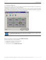
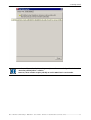
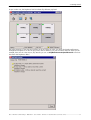
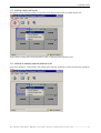
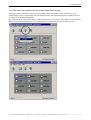
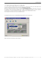
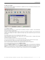
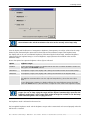
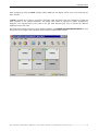
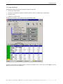
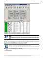
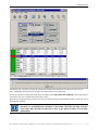
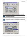
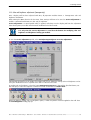
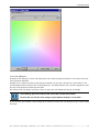
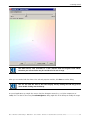
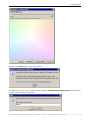
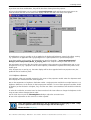
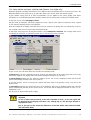
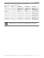
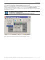
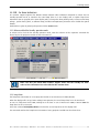
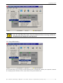
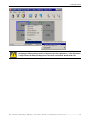
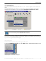
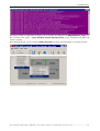
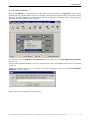


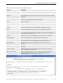
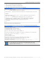
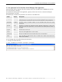
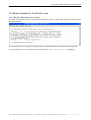

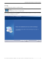
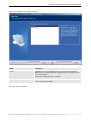
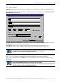
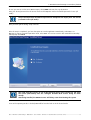
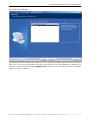
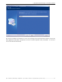
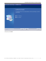
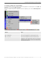
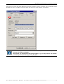
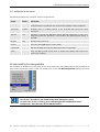
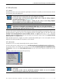
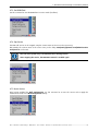
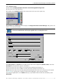
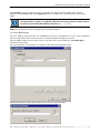
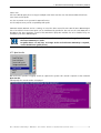
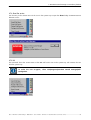

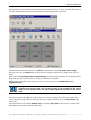
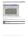
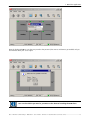
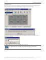
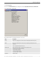
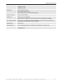
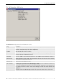
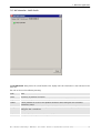
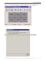
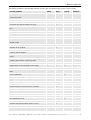
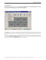
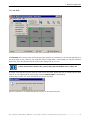

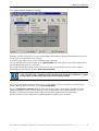
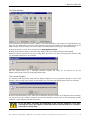
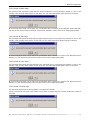
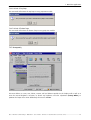
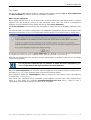
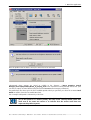
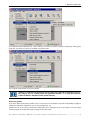
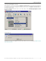
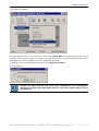
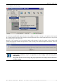
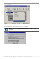
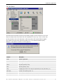
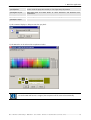
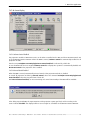
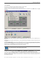
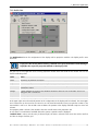
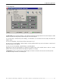
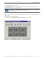
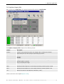
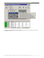

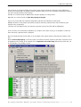
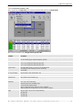
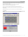
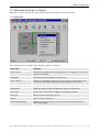
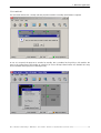
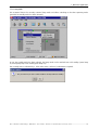
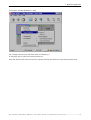
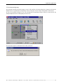
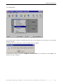
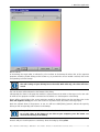
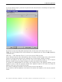
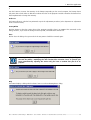
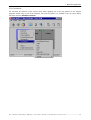
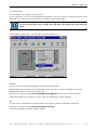
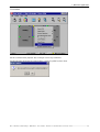
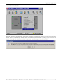
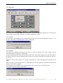
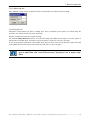
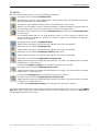
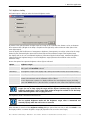
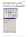
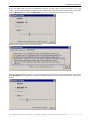
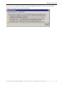

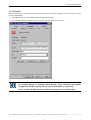
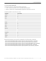
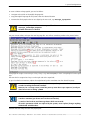
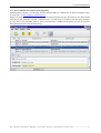
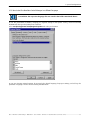
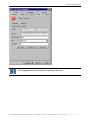
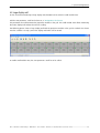
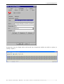
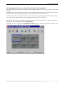
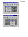
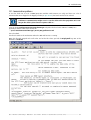
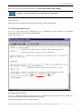

![OverView Control Manager user`s manual - operator [v04]](http://vs1.manualzilla.com/store/data/005659468_1-4c522981c7089838b286d7fbb1120c24-150x150.png)

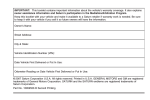


![CAST for PSI user`s manual [v07]](http://vs1.manualzilla.com/store/data/005903758_1-a858c2dfda3ffb28451a6ec48d1cfa02-150x150.png)