1
User’s manual CAST FOR OVERVIEW D SERIES DOC-3329-2 DOC-3329-2 Title: CAST for OverView D Series – User Manual ID No.: DOC-3329-2 Date: 2006-12 Revision: 04 Chapter 1 Chapter 2 Chapter 3 Chapter 4 Chapter 5 Chapter 6 Chapter 7 Chapter 8 Chapter 9 Chapter 10 Chapter 11 Chapter 12 Chapter 13 Chapter 14 Chapter 15 Primary Edition new new new new new new new new new new new new new new new Update new: The corresponding chapters were newly generated or completely revised. corr.: Parts of the corresponding chapter were corrected; see edit mark. add: Missing parts of the corresponding chapter were added; see edit mark. Document History Changes resulting in a new version are marked with a bar in the margin of the text. Do not discard this page! This manual refers to CAST Release 2.2 CAST 2.0 was the first release of CAST software to support color adjustment of the OverView D series. Firmware CAST for OverView D Series Release 2.2 supports firmware versions 2.xx, 3.xx of the projection units. In case projectors still have firmware 1.xxx, the firmware has to be upgraded! CAST for OverView D Series Release 2.2 has been modified to support the spectrometer of type USB4000. Trademarks Company and product names listed in this manual are trademarks and/or registered trademarks of their respective owners. All of the company and product names listed in this publication serve as reference or example and are not intended as advertisement for these products or manufacturers. Copyright 2001-2006 Barco Control Rooms GmbH Die Weitergabe sowie die Vervielfältigung aller Unterlagen, die von uns überlassen werden, deren Verwertung und Mitteilung ihres Inhaltes an Dritte ist nicht gestattet, soweit dies nicht ausdrücklich zugestanden ist. Urheberrechte, insbesondere auch solche an Software, werden nur insoweit übertragen, als es für die Erreichung des speziellen Vertragszwecks erforderlich ist. Zuwiderhandlungen können zu Schadensersatz verpflichten. Alle Rechte aus der Erteilung eines Patents oder der Eintragung eines Gebrauchsmusters verbleiben bei uns. Copyright 2001-2006 Barco Control Rooms GmbH All rights reserved. No part of this document may be copied, reproduced or translated. It shall not otherwise be recorded, transmitted or stored in a retrieval system without the prior written consent of the Barco Control Rooms GmbH. Warranty and Compensation for Damages The company Barco Control Rooms GmbH guarantees perfect manufacture within the scope of legal warranty periods. The buyer has to inspect the goods delivered by Barco Control Rooms GmbH for transport, material, or manufacturing damages/defects immediately upon receiving the goods. Any complaints have to be immediately submitted to Barco Control Rooms GmbH in writing. The warranty period starts with at time of risk transference and with initial operation for special systems and software but not later than 30 days after the time of risk transference. If the complaints are justified Barco Control Rooms GmbH can chose to repair or replace the goods within an appropriate timeframe. If repairs are not possible or if they failed the buyer can demand a price reduction or withdraw from the contract (cancellation). Barco Control Rooms GmbH is not liable for any additional demands, especially for direct or indirect damages as well as damages caused by operating the software or other services, system-integral or independent, provided by Barco Control Rooms GmbH, if it cannot be proven that the damage is caused or based on missing properties guaranteed in writing or that Barco Control Rooms GmbH is guilty of gross negligence or intend of defrauding the buyer. If the buyer or a third party changes, modifies, repairs, or improperly operates or uses the goods delivered by Barco Control Rooms GmbH, especially if systems are started or operated incorrectly or if goods are subjected to risks after the transfer of risk, which are not covered by the contract, the buyer's warranty claims become null and void. System failures caused by programs or special electronics supplied by the customer, e.g., interfaces, are also not covered by the warranty. Normal wear and tear as well as normal maintenance is not covered by the Barco Control Rooms GmbH warranty. The environmental conditions specified in this manual as well as the care and maintenance guidelines have to be adhered to by the customer. Corrections To • Barco Control Rooms GmbH An der Rossweid 5, D-76229 Karlsruhe Telephon: (49) (721) 6201-0, Fax: (49) (721) 6201-298 E-mail [email protected], Web www.barcocontrolrooms.de Sender: Date: Please correct the following items in the documentation Doc-3329-2 Page Incorrect Text Correction Contents 1 Preliminary Remarks ......................................................................................................................... 1-1 1.1 Overview......................................................................................................................................................1-2 1.2 Manual structure..........................................................................................................................................1-2 1.3 Numbering...................................................................................................................................................1-3 1.4 Styles and symbols......................................................................................................................................1-3 2 OverView D Series in Short ................................................................................................................ 2-1 2.1 Impaging device ..........................................................................................................................................2-1 2.2 Lamps...........................................................................................................................................................2-1 2.3 Lamp optimization.......................................................................................................................................2-2 2.4 Color wheel..................................................................................................................................................2-2 2.5 Optical dimmer ............................................................................................................................................2-3 2.6 DIS calibration factor ...................................................................................................................................2-3 2.7 Brightness – relative and absolute mode...................................................................................................2-4 3 CAST – a Tool for Color Adjustment ................................................................................................... 3-1 3.1 Introduction .................................................................................................................................................3-2 3.2 Automatic color adjustment by CAST..........................................................................................................3-2 3.3 Limitations of automatic color adjustment ................................................................................................3-2 3.4 Visual evaluation optimizes automatic adjusting ......................................................................................3-2 4 Installation and Cabling..................................................................................................................... 4-1 4.1 Requirements ..............................................................................................................................................4-2 4.2 Components of CAST....................................................................................................................................4-2 4.3 Setup ............................................................................................................................................................4-3 4.4 Update of previous releases of CAST ..........................................................................................................4-4 4.5 Spectroscope USB2000................................................................................................................................4-5 4.6 Installation of the spectroscope USB4000 (new) ......................................................................................4-9 4.7 Use of miscellaneous spectrometer ........................................................................................................ 4-12 4.8 Installation of the cordless mouse .......................................................................................................... 4-13 4.9 Remote control cabling ............................................................................................................................ 4-14 4.10 Connection settings ................................................................................................................................ 4-17 4.11 Display walls comprising more than 32 projection modules ............................................................... 4-17 4.12 Sequence of communication ................................................................................................................. 4-19 5 Color measurement and color adjustment ....................................................................................... 5-1 5.1 Introduction .................................................................................................................................................5-2 5.2 color .............................................................................................................................................................5-2 5.3 White point, hue, and saturation................................................................................................................5-3 5.4 Principle of color adjustment ......................................................................................................................5-4 5.5 Color adjustment on OverView D series .....................................................................................................5-5 5.5.1 Principle ..............................................................................................................................................5-5 5.5.1.1 Optical dimmer .................................................................................................................................... 5-5 5.5.1.2 ASIC ...................................................................................................................................................... 5-5 5.5.2 How CAST works .................................................................................................................................5-5 5.5.3 Operating conditions of CAST .............................................................................................................5-5 5.5.4 Color adjustment of projection modules equipped with the 3200K color filter cartridge ..............5-6 5.5.5 Color adjustment of projection modules equipped with Multi Input Module .................................5-6 6 Overview of adjustment steps .......................................................................................................... 6-1 6.1 Flow chart ....................................................................................................................................................6-2 6.2 CAST – options of operation ........................................................................................................................6-3 6.2.1 Recommended standard procedure: bold .........................................................................................6-3 6.2.2 Skip second measuring cycle: dotted ................................................................................................6-3 6.2.3 Modify target: dash ............................................................................................................................6-3 6.2.4 Manual improve: thin solid line .........................................................................................................6-3 6.2.5 Without any spectrometer: dash-dot-dash........................................................................................6-3 6.2.6 Adjustment of individual projection modules only...........................................................................6-4 6.3 Short Introduction to the measurement procedure...................................................................................6-5 6.3.1 Prerequisite.........................................................................................................................................6-5 6.3.2 Measurement steps ............................................................................................................................6-6 6.3.2.1 Factory colors ....................................................................................................................................... 6-6 6.3.2.2 Applying the auto target................................................................................................................... 6-12 6.3.3 Second measurement cycle ............................................................................................................ 6-15 6.3.4 Manual improvement...................................................................................................................... 6-15 6.3.5 User targets...................................................................................................................................... 6-15 7 Fully automated adjustment of the Display Wall ............................................................................. 7-1 7.1 Starting the software ..................................................................................................................................7-2 7.2 Configuration of measurement...................................................................................................................7-5 7.3 Connecting the Display Wall .......................................................................................................................7-6 7.4 Process of measurement ............................................................................................................................7-9 7.5 Measuring the factory colors ................................................................................................................... 7-10 7.6 Auto target................................................................................................................................................ 7-12 7.7 Verifying the auto-target ......................................................................................................................... 7-13 8 User-defined targets.......................................................................................................................... 8-1 8.1 General.........................................................................................................................................................8-2 8.1.1 Modifying the white point .................................................................................................................8-4 8.1.2 Modifying the color locations for the primaries................................................................................8-6 8.1.3 Individual targets................................................................................................................................8-6 8.1.4 Modification of luminance..................................................................................................................8-8 8.2 Activating the Modified target................................................................................................................. 8-10 8.2.1 Modifying a target ........................................................................................................................... 8-13 8.3 Unreachable targets ................................................................................................................................. 8-13 8.3.1 General............................................................................................................................................. 8-13 8.3.2 Not reachable: color ........................................................................................................................ 8-13 8.3.3 Not reachable: luminance ............................................................................................................... 8-14 8.3.4 Not reachable: What to do .............................................................................................................. 8-16 9 Adjusting adjacent display walls....................................................................................................... 9-1 9.1 Multi Wall Target .........................................................................................................................................9-2 10 Maintenance with CAST ................................................................................................................. 10-1 10.1 General ................................................................................................................................................... 10-2 10.2 Exchange of projection unit ................................................................................................................... 10-2 10.3 Lamp exchange ...................................................................................................................................... 10-4 10.4 Lamp ageing ........................................................................................................................................... 10-6 10.5 Maintenance without spectrometer...................................................................................................... 10-6 11 Manual adjustment........................................................................................................................ 11-1 11.1 General ................................................................................................................................................... 11-2 11.2 Fine tuning after the automated adjustment procedure ..................................................................... 11-2 11.2.1 Manual adjustment: luminance .................................................................................................... 11-5 11.3 Exclude a projector from the adjustment procedure............................................................................ 11-6 11.3.1 Before connecting CAST................................................................................................................. 11-6 11.3.2 CAST is already connected to the display wall............................................................................. 11-7 11.4 Adjusting projectors with extremely bad color locations..................................................................... 11-9 11.5 Fully manual adjustment without spectrometer ................................................................................ 11-10 12 CAST User interface ........................................................................................................................ 12-1 12.1 Menu bar of CAST ................................................................................................................................... 12-2 12.2 File menu ................................................................................................................................................ 12-2 12.2.1 New................................................................................................................................................ 12-2 12.2.2 Open............................................................................................................................................... 12-5 12.2.3 Close ............................................................................................................................................... 12-5 12.2.4 Delete wall..................................................................................................................................... 12-6 12.2.5 Multi Wall Target ........................................................................................................................... 12-6 12.2.6 Exit.................................................................................................................................................. 12-8 12.3 Wall ......................................................................................................................................................... 12-9 12.3.1 Adjustment .................................................................................................................................... 12-9 12.3.2 Measure ....................................................................................................................................... 12-10 12.3.3 Wall properties............................................................................................................................. 12-11 12.4 Lamp ..................................................................................................................................................... 12-12 12.4.1 Activate ........................................................................................................................................ 12-12 12.4.2 Exchange ...................................................................................................................................... 12-12 12.4.3 Measure ....................................................................................................................................... 12-14 12.4.4 Manual adjust .............................................................................................................................. 12-15 12.4.5 Disconnect (Connect)................................................................................................................... 12-16 12.4.6 Color&Luminance ......................................................................................................................... 12-17 12.4.6.1 Colors.............................................................................................................................................. 12-17 12.4.6.2 Luminance...................................................................................................................................... 12-19 12.4.6.3 Error status..................................................................................................................................... 12-21 12.5 Tools ...................................................................................................................................................... 12-22 12.5.1 Options ......................................................................................................................................... 12-22 12.5.1.1 General........................................................................................................................................... 12-22 12.5.1.2 Hardware ....................................................................................................................................... 12-23 12.5.1.3 Advanced ....................................................................................................................................... 12-24 12.5.1.4 How CAST determines the auto target ......................................................................................... 12-24 12.5.2 Calibrate spectrometer................................................................................................................ 12-25 12.6 Help....................................................................................................................................................... 12-27 12.6.1 Contents ....................................................................................................................................... 12-27 12.6.2 Select language ........................................................................................................................... 12-28 12.6.3 About............................................................................................................................................ 12-28 12.7 Tool bar ................................................................................................................................................. 12-29 12.7.1 Create new wall........................................................................................................................... 12-29 12.7.2 Open existing wall....................................................................................................................... 12-29 12.7.3 Connect ........................................................................................................................................ 12-30 12.7.4 Disconnect.................................................................................................................................... 12-31 12.7.5 Expected projector address ......................................................................................................... 12-32 12.7.6 Projector identification ................................................................................................................ 12-33 12.7.7 Grid view...................................................................................................................................... 12-33 12.7.8 Table view.................................................................................................................................... 12-33 12.7.9 Lamp identification...................................................................................................................... 12-34 12.7.9.1 Grid view........................................................................................................................................ 12-34 12.7.9.2 Table view...................................................................................................................................... 12-34 12.7.10 Factory colors............................................................................................................................. 12-35 12.7.10.1 Grid view...................................................................................................................................... 12-35 12.7.10.2 Table view ................................................................................................................................... 12-36 12.7.10.3 Adjusted color.............................................................................................................................. 12-37 12.7.10.4 Grid view...................................................................................................................................... 12-37 12.7.10.5 Table view ................................................................................................................................... 12-37 12.7.11 Test pattern................................................................................................................................ 12-39 12.7.12 Interrupt button ......................................................................................................................... 12-40 13 Technical Data................................................................................................................................ 13-1 13.1 Technical data of the CAST spectroscope .............................................................................................. 13-2 13.2 Technical data of the cordless mouse ................................................................................................... 13-2 14 Troubleshooting ............................................................................................................................. 14-1 14.1 Troubles .................................................................................................................................................. 14-2 15 Hotline............................................................................................................................................ 15-1 15.1 Addresses................................................................................................................................................ 15-2 1. Preliminary Remarks 1 Preliminary Remarks Barco – CAST for OverView D series – DOC-3329-2 – user's manual – Revision 04 – December-2006 _____________________________________ 1-1 1. Preliminary Remarks 1.1 Overview This chapter explains the structure of the manual as well as the applied style conventions and symbols. 1.2 Manual structure This manual is divided into 1$ chapters: Preliminary Remarks This chapter explains the structure of the manual itself as well as the applied style conventions and symbols. OverView D Series in Short Introduces the OverView D imaging device CAST – a tool for Color Adjustment This chapter explains why projection modules have to be adjusted and introduces CAST Installation and Cabling Explains the system requirements and the installation of CAST, software, spectroscope, mouse and the remotecontrol cabling Color Measurement and Color Adjustment Gives some background information on color measurement and explains how CAST works. Overview of adjustment steps Shows a flow chart of the adjustment procedure and a list which refers to the most important topcis in the manual Fully automated adjustment of a Display Wall Gives a detailed description of the various steps CAST performs during an adjustment procedure User-defined targets Explains how the target of CAST can be customized to meet special requirements or to deal with projectors of lower quality Adjusting adjacent display walls Describes how to adjust all display walls in a control room to a common target Maintenance with CAST Describes how to preserve or re-new the adjustment of a Display Wall Manual Adjustment Introduces into the adjustment procedure without spectrometer CAST user interface This chapter is a reference to the GUI and explains the menus and dialogs Technical Data Includes the technical specification of the CAST hardware spectrometer and cordless mouse Trouble shooting Lists possible problems and their solution Hotline Lists the contact addresses in case you encounter problems Barco – CAST for OverView D series – DOC-3329-2 – user's manual – Revision 04 – December-2006 _____________________________________ 1-2 1. Preliminary Remarks 1.3 Numbering Chapters, pages, illustrations, and tables are numbered separately. The chapters and the chapter sections feature a »point syntax«, e.g., 4.2.3; however, pages feature a »line syntax« 1.4 Styles and symbols The typographic styles and the symbols used in this document have the following meaning: Bold Labels, menus and buttons are printed in Bold font. Condensed Links to both other chapters of this manual and to sites in the Internet are printed condensed. In the on-line version of this manual all hyperlinks appear teal. Courier Names of files and parts from programs are printed in the Courier font. Courier bold Inputs you are supposed to do from the keyboard are printed in Courier bold font. The sheet icon indicates additional notes. Next to this icon you find further information. This arrow marks tips. Next to this icon you find important notes. Barco – CAST for OverView D series – DOC-3329-2 – user's manual – Revision 04 – December-2006 _____________________________________ 1-3 2. OverView D Series in Short 2 OverView D Series in Short 2.1 Impaging device OverView D series is based on DLP technology, using a single chip DMD. For a single-chip projection system, the DMD is sequentially illuminated with the three primary colors, red, green, and blue (RGB) Figure 2-1 principle of a single-chip DLP projection system A condenser lens collects the light, which is imaged onto the surface of a transmissive color wheel. A second lens collects the light that passes through the color wheel and evenly illuminates the surface of the DMD. The DMD is controlled by the ASIC. Depending on the rotational state of the mirror (+10 or -10 degrees), the light is directed either into the pupil of the projection lens (on) or away from the pupil of the projection lens (off). The projection lens has two functions: (1) to collect the light from each on-state mirror, and (2) to project an enlarged image of the mirror surface to a projection screen. The picture shows a color wheel with three segments red, green, and blue. It is also possible that the segments for the primaries exist twice (RGBRGB), or that a white segment is added (RGBW). OverView D series uses a color wheel with four segments, RGWB. 2.2 Lamps Projection modules of the OverView D series have dual lamp system, i.e. the illumination unit is armed with two lamps, but it is only one lamp which illuminates the optics. This lamp is called active lamp. The lamps can be operated in 3 modes: Hot Standby, Cold Standby, Auto Switch mode. In Hot Standby both lamps are on. In case of a lamp failure, the light output of the other lamp is immediately switched to illuminate the optics, and there is no noticeable effect on the displayed information: no loss of information, no impact on quality. Switching time is about half a second. In Cold Standby mode the second lamp is only switched on in case a failure occurs with the active lamp. Since the second lamp needs about one minute to reach a stable operating temperature, at the beginning the display will have reduced brightness. The contents of information, however, is available nearly without any interrupt. Auto Switch mode is a special version of the Cold Standby mode: the lamps are active in turns: every 500 hours the light path is illuminated by the other lamp. Since the lamp is switched on some minutes in advance, the takeover of the other lamp is nearly not noticeable Both lamps are taken into consideration when adjusting the Display Wall. Therefore the adjustment tool switches the Display Wall into Hot Standby mode. Please note that operating the Display Wall in Hot Standby mode is only available if activated upon special request! Barco – CAST for OverView D series – DOC-3329-2 – user's manual – Revision 04 – December-2006 _____________________________________ 2-1 2. OverView D Series in Short 2.3 Lamp optimization Since the light is coupled into the light rod by means of a mirror, the position of the mirror together with the actual lamp properties determine the light yield. During the Lamp Optimization procedure, the light output of the active lamp in dependance of the tilting angle of the mirror is measured, and the optimized mirror position for the lamp is determined. The procedure has to be performed subsequently for both lamps. The optimised positions are stored independently for both lamps, so that after setting the lamp lift in motion and thus changing the active lamp, the mirror position is adjusted accordingly. During this procedure, the display gets dark for about 30seconds. 2.4 Color wheel The color wheel incorporated in the DLP projection engine has 4 sectors: red ( R), green (G), white (W) and blue (B) "White" is generated by the primary colors, via the addition of full red, full green, and full blue. W1 = R + G + B "White" is also generated by the white segment: W2 = W "White" is also generated by the so-called spoke light recapture: If the DMD is left ON while the color segments change, there are additional contributions of adjacent segments: R+G G+W W+B B+R Spoke light recapture R G W B R Time Spoke Light Recapture (SLR) = (R+G) + (G+W) + (W+B) + (B+R) = 2*(R+G+B) + 2*W = W3 In case the white segment and spoke light recapture are activated, the white output is boosted. The White Peaking Factor is defined as the relation of "all whites" to the RGB-White: White Peaking Factor = W1 + W2 + W3 RGB + W + SLR = W1 RGB It's obvious that the minimum of the White Peaking Factor equals 1 (no white segment, no spoke light recapture). The maximum of the White Peaking Factor (all three contributions) is about 1.8. It varies slightly with different lamps The White Peaking Factor can be linear scaled between its minimum and its maximum by means of the White Peaking Value. White Peaking values are in the range between 0 and 10. (10: max. White Peaking Factor) Barco – CAST for OverView D series – DOC-3329-2 – user's manual – Revision 04 – December-2006 _____________________________________ 2-2 2. OverView D Series in Short The White Peaking Value has impacts on color adjustment. Therefore it has to be specified when using CAST. After changing the White Peaking Value, the color adjustment has to be repeated! The color correction model is only valid for one White Peaking Value setting! 2.5 Optical dimmer For brightness control, OverView D uses a dimmer wheel with a variable slit. The slit defines the light aperture of the light pipe entry. Figure 2-2 Dimmer Wheel, variable slit The amount of light emitted into the projection unit depends on the position (i.e. slit width) of the dimmer wheel. Adjusting a lamp to a given luminance requires setting the dimmer to a defined position related to this luminance Changing the dimmer position afterwards (changing the brightness) might have impacts on the color adjustment. 2.6 DIS calibration factor OverView D uses a direct illumination sensor (DIS) to measure the emitted brightness in order to keep the brightness of a constant level. The DIS controls the the dimmer. All DIS values that are displayed and used in the projector are composed by the raw data of the DIS multiplied by a calibration factor: DIS value = DIS Calibration Factor *( 1-correction factor)*DIS raw data The calibration factor ensures that the DIS values are identical the luminance values measured by the CAST spectrometer. The DIS Calibration Factor and the DIS correction factor are set for both lamps individually. Barco – CAST for OverView D series – DOC-3329-2 – user's manual – Revision 04 – December-2006 _____________________________________ 2-3 2. OverView D Series in Short 2.7 Brightness – relative and absolute mode Projectors of the OverView D series can be switched between relative and absolute brightness mode. In both operation modes the brightness is set by means of the dimmer wheel. The dimmer wheel has a characteristic which assigns a position of the dimmer wheel to a certain amount of brightness. This amount varies from 100% to 50% (it is evident that for 100% brightness the dimmer has its biggest aperture). In absolute mode, the dimmer wheel is controlled by the DIS: a target value for brightness is given, the dimmer driven into the position which should result in this brightness, then the brightness is measured, compared with the target, and depending on this result, the dimmer wheel is driven to a position with a more opened or more closed slit. In absolute mode, the brightness of a projection module can be locked: within a defined frequency, the brightness is measured by the DIS and then the dimmer wheel adjusted that the actual brightness will meet the target brightness. Normal operation mode of the OverView D projection modules is absolute brightness mode. However, the factory setting of a projection unit is relative brightness mode, since then no brightness measurements values are available to set the appropriate dimmer position. CAST calibrates the DIS in order to fine tuning the luminance: a well-defined luminance target can only be achieved by means of a control loop. As mentioned above, all DIS values that are displayed and used in the projector are composed by the raw data of the DIS multiplied by a calibration factor: DIS value = DIS Calibration Factor *( 1-correction factor)*DIS raw data For operating in absolute brightness mode, CAST determines the DIS calibration factor (individually for each lamp). Then the projection module is set to the target brightness. The adjustment procedure by means of the CAST spectrometer is done in the absolute brightness operation mode! In case the visual inspection judges a projector module to be too bright or too dark, the user then can adjust the brightness individualy by means of the correction factor. This factor can be set in the range from –30% to +30% and slightly changes the calibration of the DIS. The target value of the DIS remains constant! If CAST is used without spectromater (manual mode), there is no measurement value of the luminance available, and the projection modules are adjusted in relative mode. In relative brightness mode, the DIS calibration factor is set to one, and the correction factor is set to zero. The adjustment procedure without the CAST spectrometer is done in the relative brightness operation mode! (Afterwards then the brightness mode is switched back to absolute.) Barco – CAST for OverView D series – DOC-3329-2 – user's manual – Revision 04 – December-2006 _____________________________________ 2-4 3. CAST – a Tool for Color Adjustment 3 CAST – a Tool for Color Adjustment Barco – CAST for OverView D series – DOC-3329-2 – user's manual – Revision 04 – December-2006 _____________________________________ 3-1 3. CAST – a Tool for Color Adjustment 3.1 Introduction As known from computer monitors and TV, every device has its specific color rendering. In case this color rendering does not meet your needs, you adjust the colors until the results pleases you. Usually this is done once, and should be valid for all applications or all broadcasting, respectively. In case of a single monitor, color adjustment is quite an easy task. In case of multiple monitors which should look the same, this task is difficult: Due to production processes, the desired color rendering as set on one monitor might not be achieved by the other monitors. 3.2 Automatic color adjustment by CAST Due to tolerances, modular rear-projection Display Walls don't feature a homogenous color and brightness distribution: every projection module houses its own projection engine with its individual color rendering. CAST is a software with a measuring device which measures the factory colors of every projector. Subsequently it determines a color space which can be reached by every projection engine, and then adjusts every projection engine to this common color space. As a result the Display Wall features homogenous color and brightness. 3.3 Limitations of automatic color adjustment In spite of being a measurable property, color is an impression of a physiological sense and perceived differently by different observers, above all when looked at under different viewing angles. Therefore an observer might judge the result of the automatic color adjustment by CAST to be unsatisfying. CAST works on a formal objective basis. Human color perception is a highly subjective matter. 3.4 Visual evaluation optimizes automatic adjusting To overcome the above mentioned limitations, CAST offers in addition the possibility of a manual adjustment. After an automatic color adjustment, a visual fine tuning can be done. Barco – CAST for OverView D series – DOC-3329-2 – user's manual – Revision 04 – December-2006 _____________________________________ 3-2 4. Installation and Cabling 4 Installation and Cabling Barco – CAST for OverView D series – DOC-3329-2 – user's manual – Revision 04 – December-2006 _____________________________________ 4-1 4. Installation and Cabling 4.1 Requirements • Windows 2000 or WindowsXP • Standard PC or Laptop • Processor Pentium II 500 MHz or higher • Main memory 64 MB • Screen resolution XGA (1024×768) or higher • Interfaces: 1x USB (spectroscope) 1x USB (cordless mouse) 1x Serial (remote control) 4.2 Components of CAST CAST consists of a color measuring unit (spectrometer) [2] connected with a notebook computer via a USB interface [3], and a cordless mouse[4] with its receiver [5] to control the measurement. During measurement, the sensor [S] of the spectrometer has to touch the screen. The CAST software [1] controls the measuring instrument, processes the measured data, and adjusts the projectors via remote control. For remote control cabling , the delivery of CAST includes the connection between the laptop and the first projection engine, either a V24 cable with an adapter ([6], [7]); or a 1:1 cable with a male and a female Sub D9 interface (cable length: 15m). The shortening plug [8] is only required for projection modules of the OverView P series! Do not use it with OverView D! Figure 4-1 CAST Installation therefore comprises installation of software (CAST software) and hardware (spectrometer, cordless mouse) Barco – CAST for OverView D series – DOC-3329-2 – user's manual – Revision 04 – December-2006 _____________________________________ 4-2 4. Installation and Cabling 4.3 Setup You need administrative access rights to install CAST. Enter the CD into the computer drive and run setup.exe. The Install Shield Wizard will guide you through the installation process. Follow the displayed instructions. Figure 4-2 InstallShield Wizard The installation procedure offers a complete and a custom installation: Figure 4-3 InstallShield Wizard Select (1) Complete to install the CAST software, both versions for OverView D series and OverVierw P series as well as the spectrometer ActiveX control. Select (2) Custom to install only one of the software versions or the spectrometer ActiveX control only. Barco – CAST for OverView D series – DOC-3329-2 – user's manual – Revision 04 – December-2006 _____________________________________ 4-3 4. Installation and Cabling A folder named Barco CAST is created during the installation in the directory Program Files and shortcuts are generated as well. The following subfolders are created as well: Cast_P (complete installation or selected component with custom installation) with the subfolders Help, PSI-Backup-Settings, PSI-Factory-Settings, Template DB as well as the examples database. Help In this subfolders the help file and the manual is located TemplateDB In this subfolder an Access database named template.mdb is created . This database is prepared for the projector data, but initially contains no data. PSI-Factory-Settings It is recommended to save the PSI factory settings from the CAST CD-ROM to this folder. PSI-Backup-Settings For each wall, when restoring user settings, CAST will automatically create an appropriate subfolder to the PSI-Backup-Settings folder to save the user settings. In Tools | Options | File locations, cf. File locations¸ CAST refers to these folders. If you choose to have different folders for the PSI factory settings and PSI user settings, you have to adjust the entries on this tab accordingly! Examples There you can find some samples databases. Cast_D (complete installation or selected component with the subfolders Help, Examples, Template DB. with custom installation) Help In this subfolders the help file and the manual is located TemplateDB In this subfolder an Access database named template.mdb is created . This database is prepared for the projector data, but initially contains no data. Examples There you can find some sample databases. Inf This is the subfolder for the driver files of the CAST spectroscopes If CAST propose to restart the system, follow this advice! After re-booting, log in again with administrative rights to make sure that Windows 2000 can perform the update of the configuration files. If this update is done, no longer administrative rights are required for CAST. 4.4 Update of previous releases of CAST To update previous releases of CAST, you have to de-install the software and then to install the new release. You need administrative privileges to de-install and re-install the software! The database files of previous versions of CAST 2.0 (β versions) are not compatible! CAST Rel. 2.2 still supports the spectroscope USB2000. It is recommended to update the driver, cf. Spectroscope USB2000. Barco – CAST for OverView D series – DOC-3329-2 – user's manual – Revision 04 – December-2006 _____________________________________ 4-4 4. Installation and Cabling 4.5 Spectroscope USB2000 Check the label on the spectroscope: if it reads CST-3122-01, then the spectroscope is of type USB2000. With previous deliveries of CAST, a spectroscope of type USB2000 has been included. When updating the CAST software to rel. 2.2, it is recommended to update the driver of this spectroscope as well. In case the spectroscope USB2000 shows a strange behavior, update of the driver file is mandatory! During the installation of the CAST software the driver files of the spectroscope have been copied to C:\windows\inf. To update the driver, navigate to the entry of the spectroscope in the Windows Device Manager: Figure 4-4 The spectroscope (Ocean Optics USB2000) is listed in the Device Manager Right click on the entry of spectroscope. From the context menu, select Properties, and then activate the tab Driver. Click the button Update driver. Select the file ooi_usb.inf, located in C:\Windows\Inf Barco – CAST for OverView D series – DOC-3329-2 – user's manual – Revision 04 – December-2006 _____________________________________ 4-5 4. Installation and Cabling Figure 4-5 Driver file for the spectroscope This driver supports the spectroscope USB2000 as well as the spectroscope USB4000. However, with USB4000, in addition Java Runtime Environment has to be installed! (For USB2000, no JRE is required!) After the update of the driver, the spectroscope USB2000 gets a dedicated entry in the Windows Device Manager. It is no longer listed below the Universal Serial Bus controllers: Barco – CAST for OverView D series – DOC-3329-2 – user's manual – Revision 04 – December-2006 _____________________________________ 4-6 4. Installation and Cabling In addition to the driver files, CAST requires a calibration file, which is specific for every CAST spectroscope. When the spectroscope is connected, CAST determines its serial number and requests for the corresponding calibration file. Starting measurements without the calibration file results in the message: Figure 4-6 The calibration file is missing! If the calibration file is missing, this message also pops up when switching to the Hardware tab in Tools | Options. Every CAST spectroscope includes a calibration file. It is recommended to store this file in a safe location since it is needed again when re-installing the CAST spectroscope. If this message is ignored and CAST is started without the necessary calibration file of the CAST spectroscope no measurements will be taken by CAST. On the Hardware tab this status is notified. The serial number of the CAST spectroscope then is written in red. Barco – CAST for OverView D series – DOC-3329-2 – user's manual – Revision 04 – December-2006 _____________________________________ 4-7 4. Installation and Cabling Figure 4-7 spectrometer status is OK In regular intervals (about one year) the CAST spectroscope has to be re-calibrated in the factory, cf. Hardware. Recalibration results in a new calibration file. Before operating the CAST spectroscope, it is recommended to do a luminance calibration (cf. Calibrate spectrometer). CAST is able to manage multiple CAST spectroscopes and their corresponding calibration files. The serial numbers of the spectroscope are read and the calibration files requested if they are not available yet. All calibration files, which have been used with CAST systems, are saved in the WinNT folder in the file spectroscope.ini. If the USB interface is plugged into the laptop and not recognized when booting the laptop, unplug it, and plug it in again. It then should be recognized! Barco – CAST for OverView D series – DOC-3329-2 – user's manual – Revision 04 – December-2006 _____________________________________ 4-8 4. Installation and Cabling 4.6 Installation of the spectroscope USB4000 (new) Check the label on the spectroscope: if it reads CST-3122-11, then the spectroscope is of type USB4000. The spectroscope USB4000 requires JRE 1.4 or 1.5 or JRE 6! On the CAST CD-ROM, JRE1.5 is provided in the folder: …\Accessories\Java Runtime Environment. In case there are multiple JRE installed on a computer, make sure that JRE current version points to JRE 1.4 or 1.5 or 1.6: To check the respective registry key, select Start|RUN|Regedit Navigate to HKEY_LOCAL_MACHINE\SOFTWARE\JavaSoft\Java Runtime Environment\CurrentVersion If CurrentVersion is different from 1.4 or 1.5 or 1.6, modify the key! The CAST spectroscope has an USB interface and is being installed via Plug&Play. The following dialog is displayed when you plug in the spectroscope: Figure 4-8 Plug&Play: Found New Hardware During the installation of the CAST software the driver files for the spectrosopes have been copied to the folder …\Windows and ….\Windows\INF. No more actions to activate/enable the drivers are required. After the successful installation, the Windows Device Manager includes a new nod Ocean Optics Devices and lists CAST spectroscope as a new hardware device: Barco – CAST for OverView D series – DOC-3329-2 – user's manual – Revision 04 – December-2006 _____________________________________ 4-9 4. Installation and Cabling Figure 4-9 The spectroscope (Ocean Optics USB4000) is listed in the Device Manager In case you encounter problems with your spectroscope, navigate to the respective entry in the device manager and right-click on the device to check its properties and/or to update the driver. For location of the driver files, see above. In addition to the driver files, CAST requires a calibration file, which is specific for every CAST spectroscope. When the spectroscope is connected, CAST determines its serial number and requests for the corresponding calibration file. Starting measurements without the calibration file results in the message: Figure 4-10 The calibration file is missing! If the calibration file is missing, this message also pops up when switching to the Hardware tab in Tools | Options. Every CAST spectroscope includes a calibration file. It is recommended to store this file in a safe location since it is needed again when re-installing the CAST spectroscope. If this message is ignored and CAST is started without the necessary calibration file of the CAST spectroscope no measurements will be taken by CAST. On the Hardware tab this status is notified. The serial number of the CAST spectroscope then is written in red. Barco – CAST for OverView D series – DOC-3329-2 – user's manual – Revision 04 – December-2006 ____________________________________ 4-10 4. Installation and Cabling Figure 4-11 spectrometer status is not OK In regular intervals (about one year) the CAST spectroscope has to be re-calibrated in the factory, cf. Hardware. Recalibration results in a new calibration file. Before operating the CAST spectroscope, it is recommended to do a luminance calibration (cf. Calibrate spectrometer). CAST is able to manage multiple CAST spectroscopes and their corresponding calibration files. The serial numbers of the spectroscope are read and the calibration files requested if they are not available yet. All calibration files, which have been used with CAST systems, are saved in the WinNT folder in the file spectroscope.ini. If the USB interface is plugged into the laptop and not recognized when booting the laptop, unplug it, and plug it in again. It then should be recognized! Barco – CAST for OverView D series – DOC-3329-2 – user's manual – Revision 04 – December-2006 ____________________________________ 4-11 4. Installation and Cabling 4.7 Use of miscellaneous spectrometers When using miscellaneous spectrometers, e.g. USB2000 and USB4000, in one installation, you should keep in mind that the measurement values may differ. USB4000, for example, in principle measures colors which are more saturated. When adjusting replaced projection units to the target of a display wall, make sure to use the type of spectrometer which has been used to determine the target. In case you are not sure about the type of spectrometer, or in case this type of spectrometer is not available, re-measuring and re-adjustment of the entire display wall (including the new projection unit) is recommended! Barco – CAST for OverView D series – DOC-3329-2 – user's manual – Revision 04 – December-2006 ____________________________________ 4-12 4. Installation and Cabling 4.8 Installation of the cordless mouse CAST comes with a cordless mouse, the Ultra GT cordless optical mouse of Gyration. Its installation is quite easy; no driver files are required. The following installation instructions are copied from Gyration web page: Remove Protective Tab from Mouse The Ultra Mouse ships with a clear plastic sheet inserted beneath the battery pack. This keeps the battery from fully discharging before the product is sold. Remove the battery pack by depressing the button at the base of the mouse. Remove the plastic tab and discard. Replace the battery pack. Charge Mouse Batteries The rechargeable Ultra Mouse batteries may need to be recharged before first use. Fully depleted batteries require up to 9 hours of charge for full replenishment. To charge the mouse, simply plug the charging cradle into a standard electrical outlet and place the mouse in the cradle. The LED light on the charging cradle will light solid and the LED light on the top of the mouse will pulsate slowly. Note: The mouse does not require a full charge to operate and the batteries have no memory effect so charging it for longer or shorter times between uses will have no adverse effects. Plug in USB Receiver Turn on the computer and plug the USB receiver into an available USB port on your computer. The Ultra USB receiver will also work with USB hubs or USB extenders. Depending on your operating system, your computer may perform a brief USB Device Installation routine. If so, simply follow any on-screen instructions. Put USB Receiver into 'LEARN' Mode The LEARN button is located on the top of the USB receiver. Press the LEARN button for 2 seconds, then release. The receiver STATUS light will flash slowly indicating the receiver is now ready to be synchronized with the mouse. Synchronize Mouse The TEACH button is located on the bottom of the Ultra Mouse. Press the TEACH button and release. The STATUS light on the USB receiver will flicker for 5 seconds indicating the USB receiver has recognized and synchronized the mouse. Take the USB Receiver out of 'LEARN' Mode Press the LEARN button on the USB Receiver again for 2 seconds, then release. The receiver STATUS light will stop flashing, indicating the receiver is now in normal operating mode. This step is optional because the receiver will automatically return to Normal mode after 5 minutes. Doing so manually ensures that your receiver will not accidentally 'Learn' any other devices that may be in the vicinity. Barco – CAST for OverView D series – DOC-3329-2 – user's manual – Revision 04 – December-2006 ____________________________________ 4-13 4. Installation and Cabling 4.9 Remote control cabling Remote-Control chains up to 32 projection modules are supported. If a Display Wall comprises more than 32 projection modules, cf. Display walls comprising more than 32 projection modules Make sure that there is no SNMP agent running. Indicate the Display Wall as being unmanaged. Communication between CAST and the projection engines is done via the serial line. Before adjusting a Display Wall, the remote control cabling has to be done. It is also mandatory that all projectors have been assigned a unique projector address according the following rule: The most left projector of the top row gets the address 1, the projector next right to him the address 2 and so on (seen from front of the Display Wall) If all projectors of the top row have received an address, start with the most left projector of the second row (row below the top row) and assign him the following number. So for a Display Wall with an n×m configuration, the projector address equals P(n', m') = n' + n*(m'-1) = actual column + total columns*(actual row -1) CAST represents the Display Wall in a kind of table, the rows labeled A, B, C and so on, the columns labeled 1, 2, 3. One view depicts the expected projector addresses: Figure 4-12 expected projector addresses You can see the projector addresses expected according the rule explained above. Barco – CAST for OverView D series – DOC-3329-2 – user's manual – Revision 04 – December-2006 ____________________________________ 4-14 4. Installation and Cabling After production, every projector has the projector address 255. To assign the correct projector address, proceed as follows: • Press the ADJ key on the RCU to display the menu bar. OverView DG Operation Lamps Status Brightness Figure 4-13 menu bar of the OSD • Move the cursor to Brightness • Enter the access code for the service menu via the numeric keys on the IR Remote-Control. The Service menu entry is shown. • Move the cursor to Projector Address. • Press Enter to select. OverView DG Operation Lamps Status Brightness Service White Peaking... Internal Patterns 4 Color Coordinate Adjustment... Orientation 4 Color Wheel Adjustment... Set Brightness... Get Brightness 4 Projector Address... Runtime Warning ... 4 Optical Dimmer 4 Restore Default Settings 4 Degamma DIS Calibration Factor... Take Screenshot ... More ... Figure 4-14 service menu of the OSD The projector address and the common RC5 address is displayed. Projector addresses Projector address 5 Common RC5 address 0 Figure 4-15 projector address To change a value: • Move the cursor key to the respective field. • Enter the new value by means of the numeric keys of the IR Remote-Control. The Remote-Control cable from the Laptop to the first projection is a 1:1 cable with a male and female Sub D9 interface. Barco – CAST for OverView D series – DOC-3329-2 – user's manual – Revision 04 – December-2006 ____________________________________ 4-15 4. Installation and Cabling CD 1 DSR 6 RxD 2 RTS 7 TxD 1 2 7 RTS 3 CTS 3 8 4 DTR 9 RI 5 GND 9 GND 5 From PC TxD 8 CTS DTR 4 RI CD 6 DSR RxD To Projector This cable can be ordered as R9827560 (length: 15m) The projection units have an interface labeled RS232 IN and RS232 OUT • RS232 IN: This female D9-pin connector is used to connect the first projection engine with the computer. By means of this connector, all other projection engines are connected to the previous projection engine in chain. • RS232 OUT: This male D9-pin connector is used to drive the next projector in a chain. Plug the communication cable from the PC into the RS232 IN socket of the first projection engines. • connect all other projection engines to the remote-control chain by connecting the remote-out socket of the previous engine to the remote-in socket of the following engine by means of the communication cable included in the projection modules. This kind of cabling is called daisy chain. Figure 4-16 remote-control cabling For OverView D series, you can either use the 15m 1:1 cable or the VGA cable together with the adapter. However, with OverView P series, the VGA cable and adapter is mandatory. There is a high risk of dammaging the controller when using the 15m 1:1 cable! As every projector has its own unique projector address there are no requirements for the routing of the chain. But to be able to maintain an installation it is recommended to route cables in a horizontal or vertical way between the projectors. Barco – CAST for OverView D series – DOC-3329-2 – user's manual – Revision 04 – December-2006 ____________________________________ 4-16 4. Installation and Cabling Before starting a communication with RS232, every projector must have a different projector address. Maximum allowed channels in one RS232 chain are 64. It is recommended to use only 32 channels with one RS232 driver. Use multiple outputs for Display Walls which comprise more than 32 channels! 4.10 Connection settings The physical medium for data transfer is based on a RS-232-C interface: signal level baud rate RS-232-C 9,600 baud Defines the speed of data transfer, For projection modules with firmware 3.x, baud rate can be set to 115200 CAST will not disable the IR receiver. Please DO NOT adjust a Display Wall with CAST and try to control a projection unit by means of the IR Remote-Control. 4.11 Display walls comprising more than 32 projection modules For large Display Wall the wall has to be divided into multiple chains, each of them having at most 32 projection modules. When creating a new wall which has more than 32 modules, a warning pops up: Figure 4-17 CAST warning Click OK to proceed. Barco – CAST for OverView D series – DOC-3329-2 – user's manual – Revision 04 – December-2006 ____________________________________ 4-17 4. Installation and Cabling CAST shows the expected Remote-Control addresses for every projector (example: 20x4 configuration) Figure 4-18 expected RC addresses in large Display Walls Now this Display Wall has to be devided into 3 chains, since one chain does not comprise more than 32 projection modules. The projection modules of a chain have to form a rectangle. It is recommended to have approximately the same number of modules in a chain. The following picture shows the modules allocated to chain 1 (rectangle, straight line), allocated to chain 2 (rectangle, dashed line), and allocated to chain 3 (rectangle, dotted line). Figure 4-19 dividing the Display Wall into multiple chains In the current release 2.0 CAST for OverView D series does not fully support Display Walls larger than 32 projection modules. As a work around, when CAST has reached the end of one chain, it displays a message during which the user can switch between the serial cables and then he can proceed the measurement by clicking Retry on the current CAST warning. CAST then will do the adjustment procedure "chain for chain". Barco – CAST for OverView D series – DOC-3329-2 – user's manual – Revision 04 – December-2006 ____________________________________ 4-18 4. Installation and Cabling 4.12 Sequence of communication Figure 4-20 communication process Barco – CAST for OverView D series – DOC-3329-2 – user's manual – Revision 04 – December-2006 ____________________________________ 4-19 5. Color measurement and color adjustment 5 Color measurement and color adjustment Barco – CAST for OverView D series – DOC-3329-2 – user's manual – Revision 04 – December-2006 _____________________________________ 5-1 5. Color measurement and color adjustment 5.1 Introduction Display walls are installed wherever computer information or videos have to be presented on a large area. Stacking and stringing of projection modules yield display walls in any desired size while retaining the original brightness level. Production processes cause color deviations with the image sources, which are unpleasant to the human eye. CAST is a Color Adjustment Service T ool developed to measure the tristimulus value of the imaging devices and to adjust these values to a common value range. The thus adjusted imaging devices then yield a display wall featuring a homogeneous color and brightness distribution. to adjust these values to a common value range. The thus adjusted imaging devices then yield a display wall featuring a homogeneous color and brightness distribution. 5.2 color Color is an impression of a physiological sense. By means of the "CIE 1976" chromaticity diagram color can be described by its coordinates. G R B Figure 5-1 CIE 1976 chromaticity diagram If three points in this diagram are selected and combined to a triangle every color within this triangle can be created by mixing the three colors placed at the corners. With display devices, usually Red, Green, and Blue are selected colors placed at the corner. These colors are called primaries. Barco – CAST for OverView D series – DOC-3329-2 – user's manual – Revision 04 – December-2006 _____________________________________ 5-2 5. Color measurement and color adjustment 5.3 White point, hue, and saturation On the straight line defined by a color located on the outline of the triangle and the white point, the hue of this color remains the same, but the saturation decreases towards the white point. G W R B* B Figure 5-2 moving from B* to W, hue remains constant, saturation decreases Barco – CAST for OverView D series – DOC-3329-2 – user's manual – Revision 04 – December-2006 _____________________________________ 5-3 5. Color measurement and color adjustment 5.4 Principle of color adjustment Due to production processes, imaging devices have native color deviations. In case of two imaging devices, the two color triangles might look like this: G1 G2 R1 B1 R2 B2 Figure 5-3 color triangles of two imaging devices (schematic) A Display Wall housing these imaging devices features rather inhomogeneous color and brightness. Therefore the projection engines have to be adjusted to a common color triangle. It is obvious that the common color triangle is the intersection of the individual color triangles. G1 G2 G* R* R1 R2 B* B1 B2 Figure 5-4 common color triangle Compared to the color locations before adjustment, the primary colors of the adjusted imaging devices are less saturated. Besides the luminance has decreased. Barco – CAST for OverView D series – DOC-3329-2 – user's manual – Revision 04 – December-2006 _____________________________________ 5-4 5. Color measurement and color adjustment 5.5 Color adjustment on OverView D series 5.5.1 Principle With OverView D series, there are two components to balance color and brightness: Brightness is controlled via the optical dimmer which adjusts the light flux. Color can be adjusted by the ASIC controlling the DMD chip. 5.5.1.1 Optical dimmer The optical dimmer is controlled by the DIS (direct illumination sensor). If the DIS is correctly calibrated, any desired brightness value (within the available range of the lamp) can be set. Therefore CAST has to calibrate the DIS! 5.5.1.2 ASIC The ASIC has to be told the uncorrected color locations and the total white, and the desired color location. Based on these information, an algorithm is applied to adjust the parameters. CAST has to provide the uncorrected color locations (factory colors) and the target color location (Auto target, user-defined target) 5.5.2 How CAST works CAST has to calibrate the DIS and to provide the necessary information about color locations to the ASIC. CAST uses a spectrometer for measurement. The spectrometer has been calibrated by aid of a lux meter, thus CAST then in turn can calibrate the DIS by measuring the brightness of a lamp and setting these values into relationship to those measured by the DIS. The spectrometer also measures the uncorrected color locations of all lamps, and CAST then calculates a common target for all lamps, the Auto target. The information about the uncorrected color locations and the desired color locations is given to the ASIC which then applies the appropriate algorithm to adjust the colors. 5.5.3 Operating conditions of CAST For the color adjustment of optical engines which are used in rear projection modules measurements of the uncorrected primary colors are required. These measurements will be done in the field at the final installation under different ambient light conditions. Even if the rear projection principle is much less sensitive to the ambient light, the measured color coordinates might be wrong by the impact of the ambient light. Due to the laws of color mixing, red and blue are expected to suffer most under the spoiling effect of the background light Especially in blue, for a real precision measurement it is mandatory to dimm down the ambient light. To achieve an accuracy in u’, v’ of better than ± 0.001 when measuring on a 50" screen, it is recommended to ensure an outside illumination of the screen by less than 50 Lux. For larger screen sizes the upper limit becomes even smaller! Barco – CAST for OverView D series – DOC-3329-2 – user's manual – Revision 04 – December-2006 _____________________________________ 5-5 5. Color measurement and color adjustment The upper limit of the ambient light is calculated according the following rule: 50 upper limit = 50 Lux ∗ screensize 2 with screensize is the screen diagonal value (in inch) Please note that the upper limit might also depend on the stray element of the screen. During measurement, it is mandatory that • the backside of the projection modules is closed by the backside sheetmetal shielding • the CAST sensor is pressed tightly on the screen to avoid the direct detection of ambient light. 5.5.4 Color adjustment of projection modules equipped with the 3200K color filter cartridge If the projection modules are operated with the 3200K color filter cartridge, also adjustment is done with this filter employed! Always use CAST on the actual operation conditions of a display wall! Modifying any paramters after the adjustment of CAST (filter, white peaking etc.) will have impact on the homogeneity of the adjustment! 5.5.5 Color adjustment of projection modules equipped with Multi Input Module If the projection modules are operated with a Multi Input Module, proceed as follows: • Use input signals VGA-RGB • Perform a color adjustment with CAST • Perform a manual fine tuning to get the best result on internal patterns • Perform an adjustment on the Multi Input Modules (cf. chapter 3.8 in the user manual of the Multi Input Module!) Barco – CAST for OverView D series – DOC-3329-2 – user's manual – Revision 04 – December-2006 _____________________________________ 5-6 6. Overview of adjustment steps 6 Overview of adjustment steps Barco – CAST for OverView D series – DOC-3329-2 – user's manual – Revision 04 – December-2006 _____________________________________ 6-1 6. Overview of adjustment steps 6.1 Flow chart CAST uses a spectrometer to measure the native color locations of the two combinations projection unit-lamp top and projection unit – lamp bottom of every projection module. The native color locations are called Factory Colors. The measured values of all projection modules are taken into consideration when calculating a common color location, a so-called target. Then the projection units and its lamps are adjusted to this calculated target. The user may stop the adjustment procedure whenever he wants to. In case of a later resume, CAST starts exactly with the following step of the aborted procedure. Figure 6-1 flow chart of adjustment Barco – CAST for OverView D series – DOC-3329-2 – user's manual – Revision 04 – December-2006 _____________________________________ 6-2 6. Overview of adjustment steps 6.2 CAST – options of operation The flow chart shows all possible options how to operate CAST. For better overview, the different ways are drawn in different styles. 6.2.1 Recommended standard procedure: bold This flow shows the fully automated adjustment process, cf. Fully automated adjustment of the Display Wall. It comprises two measuring cycles, one to measure the factory colors, the second to measure the adjusted colors (Auto target). If desired, the measurement procedure can be followed by a manual fine tuning, cf. Fine tuning after the automated adjustment procedure. 6.2.2 Skip second measuring cycle: dotted The second measuring cycle is optional. Please note that the second measuring cycle lasts at least twice as long as the first one! First the distance of the actual color location to the target is measured, then the correction is calculated, applied, and again the distance to the target is measured. In case of large Display Walls where measuring requires the use of a ladder or rack, trained personnel may skip the second measuring cycle and decide either to accept the result of the first adjustment or to manually improve individual modules, cf. Manual adjust. Using this method, no proof for the quality of the adjusted colors (measurement results) will be available. The quality of the adjustment will be lower 6.2.3 Modify target: dash If you are not satisfied with the quality of the Auto target (e.g. the Display Wall is too dark or has an unacceptable white color), you can modify the target and apply a user-defined target. CAST will then calculate a new inital correction for all modules, cf. User-defined targets. This must be done before the second measuring cycle or any manual improvements 6.2.4 Manual improve: thin solid line If you are not satisfied with the end result of the automatic adjustment, you can manually improve the adjustment. Manual improve can also be used to maintain the adjustment quality during the operation of a wall, cf. Manual adjust. 6.2.5 Without any spectrometer: dash-dot-dash This adjustment procedure requires skilled personnel who is very experienced in adjusting Display Walls. The dual lamp system involves that both lamps of a projector have to fit into a target. The bigger the Display Wall, the more difficult the task, cf. Fully manual adjustment without spectrometer In this adjustment mode, every command related to measurement or to spectrometer is disabled. Barco – CAST for OverView D series – DOC-3329-2 – user's manual – Revision 04 – December-2006 _____________________________________ 6-3 6. Overview of adjustment steps 6.2.6 Adjustment of individual projection modules only With CAST, the entire Display Wall is adjusted to homogeneous brightness and color, using one of the procedures described above. However, these options are also available for an individual combination projector-lamp, e.g. in case the projection unit or a lamp has been exchanged and has to be adjusted to the target of the Display Wall, cf. Exchange Barco – CAST for OverView D series – DOC-3329-2 – user's manual – Revision 04 – December-2006 _____________________________________ 6-4 6. Overview of adjustment steps 6.3 Short Introduction to the measurement procedure 6.3.1 Prerequisite When CAST is connected to the Display Wall, it knows the configuration, and it looks if all projection modules respond to the supposed address. In case a projection module does not react, it is excluded from the adjustment procedure. In case you want to exclude one or more projection modules on purpose, there are three possibilites: • Switch off the main power of the projector • Switch the projector to standby, and clear the checkbox "Switch on all projectors" in the Connect dialog • Assign an unexpected address to the projection module In case CAST requires a confirmation about the missing projector, acknowledge it. In case the address matches, CAST switches the projector to Hot Standby mode. Before being disconnected, CAST will switch the projectors back to their previous operation mode. Then CAST drives the dimmer wheel to its position with the maximum transmission. (If the dimmer has been disabled, CAST first enables it.) In case the dimmer cannot be enabled (dimmer wheel broken), the command to enable the dimmer results in a dark projector. Exclude this projector from the adjustment procedure, see above! (Or replace the dimmer wheel first and then perform the adjustment of the Display Wall). For both lamps, the DIS calibration factor is set to 1, the DIS correction factor is set to 0, and Brightness is set to relativ. CAST then adjusts the tiltable mirror to maximize the lamp output. This Lamp optimization is performed for both lamps, and the position of the mirror is saved for each lamp individually. In case the Display Wall has been switched off, operated in Cold Standby mode or in Auto Switch mode, thus CAST having ignited the second lamp, CAST will wait with Lamp optimization until all lamps of all projectors are warmed up. During this time, the application shows an hourglass, and the status bar of the CAST window informs about "waiting for projectors". CAST performs Lamp optimization the first time it is connected to the Display Wall. Any subsequent connection will not trigger Lamp optimization. However, lamp optimization can be triggered manually by selecting Lamp | Exchange and selectingthe related checkbox. Barco – CAST for OverView D series – DOC-3329-2 – user's manual – Revision 04 – December-2006 _____________________________________ 6-5 6. Overview of adjustment steps Now the adjustment procedure can be started. 6.3.2 Measurement steps CAST includes a spectrometer to measure the color locations of the projection engines as well as a software to determine a common color location . The respective correction then is done by the DLP ASIC. For a real precision measurement, it is mandatory to dimm down the ambient light, cf. Operating conditions of CAST As an inherit feature of the one chip DLP technology used in CAST, the color distribution in one projector is quite homogeneous. Therefore locally only one measurement point is required. Since the OverView D series feature a dual lamp system, and since color and brightness are dependent on the lamp, in a measurement series the two lamps are activated in sequence, and the color locations for both lamps are determined. CAST measures in the middle of a projection module. The measurement sequence is white, red, green, blue. Thus per lamp, one location for R, G, and B is determined as well as a position for the white point and the luminosities related to the colors. Thus per projection unit, two locations for R, G, B, and white are measured. 6.3.2.1 Factory colors Measuring the Factor Colors (uncorrected color location) is the first measurement cycle. CAST measures the uncorrected color locations for red, green, blue, and white as well as their luminosity. By comparing the DIS values with the values of the CAST spectrometer, the DIS calibraton factor and the DIS correction factors are determined. Thus later entering a target value for brightness, the dimmer wheel controlled by the DIS will be positioned accordingly. The measurements are done subsequently for both lamps. It is thus possible to receive the threshold values (corners) of the color triangle for every lamp. The adjustment can only take the direction towards the inner of the triangle CAST then calculates a common color location and a common luminance, the Auto target, and applies it to the Display Wall.. This calucation considers all lamps to ensure that the color adjustment of the Display Wall does not change when changing the active lamp. After the first measuring cycle the wall should be already quite well adjusted. If the target color and the homogeneity of the wall are already satisfying, you can disconnect from the wall. The second measuring cycle is optional. You might also consider to improve the result manually. The result of this measurement is visualized on the Color tab of the Lamp|Color&Luminance dialog. The caption indicates both, the projection module and the lamp. Barco – CAST for OverView D series – DOC-3329-2 – user's manual – Revision 04 – December-2006 _____________________________________ 6-6 6. Overview of adjustment steps Figure 6-2 color triangle of the top lamp, measured by CAST If you zoom in the graphic (right mouse click), you can have a detailed look on measurement points for white and the primaries. You can also use the zoom option on the dialog sheet. The following pictures show the color location for white and for red: Barco – CAST for OverView D series – DOC-3329-2 – user's manual – Revision 04 – December-2006 _____________________________________ 6-7 6. Overview of adjustment steps Figure 6-3 white location Figure 6-4 location for red In the zoom view the color coordinates are indicated (bottom left). Barco – CAST for OverView D series – DOC-3329-2 – user's manual – Revision 04 – December-2006 _____________________________________ 6-8 6. Overview of adjustment steps If you zoom in the white location, also the correlated color temperature is displayed. Figure 6-5 correlated color temperature, Planck curve The Planck curve is displayed as a dotted line, the distance between two dots is 100K. The dot of the Planck curve which has the least distance to the white point is taken as reference point, and the corresponding temperature is indicated in the bitmap as the correlated color temperature. To "select" a color temperature, scan the bitmap with the mouse, watch the value of the displayed temperature, and if it meets your desires, double click in the bitmap to define the white point. Barco – CAST for OverView D series – DOC-3329-2 – user's manual – Revision 04 – December-2006 _____________________________________ 6-9 6. Overview of adjustment steps CAST measures the factory colors of every projector for both lamps. All color locations can be seen by clicking All projectors in the dialog sheet. Due to the dual lamp system, a n×m configuration shows 2*(n*m) measuring points (color locations). Figure 6-6 location of white of all lamps of the Display Wall Figure 6-7 color location for red of all projectors In addition to the deviation of color locations, imaging devices also differ in brightness due to different luminance values. Barco – CAST for OverView D series – DOC-3329-2 – user's manual – Revision 04 – December-2006 ____________________________________ 6-10 6. Overview of adjustment steps CAST also determines the luminance of all lamps and adjusts them to a common luminance which of course cannot be higher than the luminance of the “darkest” lamp. The luminance of all lamps are visualized on the dialog Lamp|Color&Luminance|Luminance Figure 6-8 luminance distribution of all lamps This example shows 8 lamps (4 projection modules) with factory luminance values ranging from 289lx to 309 lx. Barco – CAST for OverView D series – DOC-3329-2 – user's manual – Revision 04 – December-2006 ____________________________________ 6-11 6. Overview of adjustment steps 6.3.2.2 Applying the auto target Based on the measurements of the factor colors, CAST calculates common color locations for the primaries and for the white point, the so-called Auto target. To see the result of this calculation, click the checkbox Auto target on Lamps | Color&Luminance | Color. Figure 6-9 white point of Auto-Target Barco – CAST for OverView D series – DOC-3329-2 – user's manual – Revision 04 – December-2006 ____________________________________ 6-12 6. Overview of adjustment steps Figure 6-10 color location for red of the Auto-Target As explained above, the common color locations and thus the common color triangle is inside the color triangles of all lamps. The Auto-Target calculated by CAST can be achieved by all projectors, no matter which lamp is selected the active lamp. Also customized target can be defined for the projectors, cf. User-defined targets After the adjustment procedure, all projectors feature the same color locations and therefore the entire Display Wall features a homogeneous color . Barco – CAST for OverView D series – DOC-3329-2 – user's manual – Revision 04 – December-2006 ____________________________________ 6-13 6. Overview of adjustment steps After the adjustment procedure, the luminance distribution is more homogeneous and all lamps have similar luminance values. Figure 6-11 luminance distribution after adjustment Even when changing the active lamp e.g. due to a lamp failure, or if the activation time of a lamp in Auto Switch mode has expired, the new lamp fits in the target (provided, of course, the lamp has not been replaced by a lamp which has not been installed while doing the adjustment procedure). Barco – CAST for OverView D series – DOC-3329-2 – user's manual – Revision 04 – December-2006 ____________________________________ 6-14 6. Overview of adjustment steps 6.3.3 Second measurement cycle The second measurement cycle can either be performed on the Auto target or on a user-defined target. • In case you are satisfied with the Auto target, and just want to further improve the homogeneity of the Display Wall, perform the second measuring cycle on the Auto target. • In case the Auto target does not meet your needs (too dark, saturation of colors too low, etc.), it can be modified. This user-defined target then is applied to the Display Wall, and the color locations are measured and verified during the second measurement cycle. To save time, verification can be skipped on the second measurement cycle, cf. Advanced. 6.3.4 Manual improvement This operation is always performed on a single lamp only. No spectrometer is required. The projection module is adjusted "by eye". 6.3.5 User targets CAST calculates the Auto target and adjusts the projectors accordingly. The user has the possibility to modify this target by creating user targets and specifying the color coordinates of white and the primaries and/or the luminance. The auto-target as well as all user-defined targets are stored in the wall database and can be applied liberally to the wall. Barco – CAST for OverView D series – DOC-3329-2 – user's manual – Revision 04 – December-2006 ____________________________________ 6-15 7. Fully automated adjustment of the Display Wall 7 Fully automated adjustment of the Display Wall Barco – CAST for OverView D series – DOC-3329-2 – user's manual – Revision 04 – December-2006 _____________________________________ 7-1 7. Fully automated adjustment of the Display Wall 7.1 Starting the software Select Start | Programs | Barco CAST | Cast-D to start the software. Figure 7-1 starting the software The About dialog is displayed. Figure 7-2 CAST About dialog Barco – CAST for OverView D series – DOC-3329-2 – user's manual – Revision 04 – December-2006 _____________________________________ 7-2 7. Fully automated adjustment of the Display Wall Then the main window of CAST is opened. Figure 7-3 CAST main window CAST stores all information about a Display Wall in a database file. During installation, some sample databases have been created in the folder C:\Program Files\Barco Cast\Cast_D\Examples . To use CAST in the field, the user has to create a new database at his desired location. Select File | New to create a new database. In this file, CAST will mainly store the following information in the wall: • The configuration of the Display Wall • the product information of the projection unit and the illumination unit • Serial number of the lamps and its operation time • Factory colors of the projection unit operated with lamp top and operated with lamp bottom • The automatic calculated color locations for all projection modules (both lamps are taken into consideration (auto-target) • User defined targets Barco – CAST for OverView D series – DOC-3329-2 – user's manual – Revision 04 – December-2006 _____________________________________ 7-3 7. Fully automated adjustment of the Display Wall Select File | New to create a new wall. The following dialog pops up: Figure 7-4 define a new wall, basic tab Please enter the required information. Customer, Location, and Wallname are fields to identify the wall, Columns and Rows are mandatory for CAST. Creation Date and Technician are filled in automatically. On the Advanced tab, the white peaking value has to be entered. Figure 7-5 define a new wall, advanced tab The White Peaking value has to be set to 10. All other values require a signed request of the customer! Check Manual mode if you don’t want to use a spectrometer but do exclusively visual adjustment. To learn more about the manual mode, cf. Manual adjustment Before you can start using CAST, some customizations have to be done: the serial port has to be configured, and a measurement sequence has to be selected. Barco – CAST for OverView D series – DOC-3329-2 – user's manual – Revision 04 – December-2006 _____________________________________ 7-4 7. Fully automated adjustment of the Display Wall 7.2 Configuration of measurement • Define the serial port (Remote Control) Select Tools | Options | Hardware and enter the serial port. Figure 7-6 hardware tab • Define the baud rate (Remote Control) Select Tools | Options | Hardware to define the baud rate. Projectors with firmware 3.x may be operated at 115200, for projectors with firmware 2.x 9600 is mandatory!. • Define a measurement sequence by selecting one of the proposals in Tools | Options | General | Select modules in this order. This setting has nothing to do with the projector sequence in the remote cable linkup but serves only to optimize the measuring order concerning the length of the USB cable. With the selected sequence (pressed button ), measurement will start on the upper left module, down the first column, on bottom row switching to the next column and so on. The last module to be measured will be the upper right one. Figure 7-7 Tools | Options | General tab To perform the required adjustment procedure, CAST has to be connected to the wall. Barco – CAST for OverView D series – DOC-3329-2 – user's manual – Revision 04 – December-2006 _____________________________________ 7-5 7. Fully automated adjustment of the Display Wall 7.3 Connecting the Display Wall Make sure that the projector addresses are assigned in the requested order. Switch to the remote control view to see the expected device numbers Figure 7-8 expected projector address (CAST has not been connected yet • Click on the red Connect icon of the toolbar Figure 7-9 connect icon After clicking onto the red connection icon, CAST warns about the interference of the OSD and CAST: Barco – CAST for OverView D series – DOC-3329-2 – user's manual – Revision 04 – December-2006 _____________________________________ 7-6 7. Fully automated adjustment of the Display Wall Figure 7-10 CAST warning After confirmation (and – hopefully – doing as been advised!), the following dialog pops: Figure 7-11 Connect dialog If it is a new wall and CAST will be connected to it the first time, lamp optimization should be performed in order to ensure that the tiltable mirror is in its adjusted position with respect to the lamp. Therefore the respective check box is selected. To learn more about lamp optimization, cf. Lamp optimization Lamp optimization is only performed when connecting to the Display Wall for the first time. To define a target for all lamps and all projectors of the Display Wall, it is mandatory that all projectors are switched on. CAST will care for this, provided the checkbox Switch on all projectors is selected. In case there are good reasons to exclude some projectors from the adjustment procedure, switch the projectors off and remove the tick of this checkbox. The disabled options are only to inform about the status of the Display Wall. CAST performs the required actions by itself. If desired, infrared control can be checked in order to be able to e.g. check some values/settings during running CAST. However keep in mind that CAST cannot work properly if the projectors are sent any commands by IR Remote-Control while doing the adjustment procedure! Click on Connect to establish the connection. The background of the grid changes from grey (not connected) to white (connected) When connecting, CAST will read the serial number of the projection unit, the illumination unit as well as the lamp operating hours. All these information then are displayed in the various view. Barco – CAST for OverView D series – DOC-3329-2 – user's manual – Revision 04 – December-2006 _____________________________________ 7-7 7. Fully automated adjustment of the Display Wall Click on Projector Identification to see the serial numbers of the components: Figure 7-12 Projector identiification Select Lamp identification to view the operating hours of the lamps. Since there are two lamps, each cell of the projector grid is subdivided into two parts: the upper one is dedicated to the top lamp, the lower one to the bottom lamp: Figure 7-13 lamp identification Whenever the grid is subdivided, the entries in bold indicate the currently active lamp of the projection module. In the picture above, all projection units are illuminated by the bottom lamp. A subdivided grid is also used in the view for the factory colors and for the adjusted colors. This is easy to understand if we keep in mind that it is not only the projection unit, but the combination projection unit-lamp which generate color. Barco – CAST for OverView D series – DOC-3329-2 – user's manual – Revision 04 – December-2006 _____________________________________ 7-8 7. Fully automated adjustment of the Display Wall If you click on Factory colors, the view changes as follows: Figure 7-14 Factory colors, not measured yet As long as no measurement has been performed, the cells depict a question mark. The digit in the upper right corner shows the number of performed measurement cycles. 7.4 Process of measurement During measurement, the CAST spectrometer has to be positioned at the center of the screens. It is recommended to dimm down the ambient light, cf. Operating conditions of CAST. Due to the dual lamp system and the influence of the lamp on the color location, both lamps have to be activated in turn, and the measurement has to be performed on both lamp. A measurement cycle comprises the following steps: With the active lamp, CAST applies the following test pattern and measures the related color location: Red, Green, Blue, White. White is measured several times at multiple dimmer positions in order to get a calibration factor and a correction factor for the DIS. The DIS calibration factor and the DIS correction factor transform the signal of the DIS in the same value and unit as achieved with the lux meter. CAST then activates the second lamp, and measures the related color location for red, green, blue, white. White is measured several times at multiple dimmer positions in order to get a calibration factor and a correction factor for the DIS. The DIS calibration factor and the DIS correction factor are stored for both lamps individually. The projection modules are measured in the sequence as defined on the tab Tools | Options | General Barco – CAST for OverView D series – DOC-3329-2 – user's manual – Revision 04 – December-2006 _____________________________________ 7-9 7. Fully automated adjustment of the Display Wall 7.5 Measuring the factory colors The factory colors are the native color locations of a projection engine illuminated by a lamp. Factory colors have the max. possible saturation. CAST displays a rectangle in the center of the screen. position the CAST spectrometer inside this rectangle. Make sure that the sensor is hold tight on the screen, and that the position of the spectrometer remains the same without “drift”. In case of a drift, the sensor might measure the white line of the rectangle instead of the test pattern! When measuring, hold the spectroscope perpendicular to the screen. The spectroscope has to touch the screen! Never remove the scattering pane of the sensor! Select Wall | Measure to start the measurement procedures. The following dialog pops up. Figure 7-15 Starting the measurement the caption indicates the lamp to be measured Click on Measure to start the measurement on the projection module A1. The measurement of lamp top is automatically followed by the measurement of lamp bottom. After both lamps of the projection module have been measured, the measurement is continued on the next projecton module in sequence. Position the CAST spectrometer, and click Measure to go on with the adjustment procedure. Whenever the projection module changes, CAST waits for an acknowledge that the spectrometer has been positioned the right way and the measurement can be proceeded. Click on OK to go on with the procedure. Press ESC to interrupt the measurement sequence (or use the mouse and right click) Whenever you cancel a measurement and resume it later, CAST knows which projection engines and which lamps have already been measured, and starts automatically with the first projection module in the chain which has not been (completely) measured. Barco – CAST for OverView D series – DOC-3329-2 – user's manual – Revision 04 – December-2006 ____________________________________ 7-10 7. Fully automated adjustment of the Display Wall If the measurement has been performed for both lamps of all projection modules, the grid depicts a tick. In the status bar the colors are indicated. Figure 7-16 Factory colors are measured CAST determines a common color locations, the so-called Auto Target, and loads the new values: Figure 7-17 CAST applies the common target Click on OK to apply the Auto Target to the Display Wall. The colors are adjusted, and in the status bar the target is named. Figure 7-18 Auto target is applied to the Display Wall Barco – CAST for OverView D series – DOC-3329-2 – user's manual – Revision 04 – December-2006 ____________________________________ 7-11 7. Fully automated adjustment of the Display Wall 7.6 Auto target After the factory colors of all projection engines have been measured, CAST determines the best target (AutoTarget) for the Display Wall and suggests to load this target to the wall. The Auto-Target is the common color location and luminance CAST determines after having measured the factory color locations and luminances. You might be already satisfied with the result of applying the Auto target. Apply one or more of the test pattern to see how the Display Wall looks in e.g. white or red or with the original application of the customer. Figure 7-19 choose test pattern A dialog pops up where you can select a color and/or a test pattern to apply to the Display Wall: Figure 7-20 available test pattern Barco – CAST for OverView D series – DOC-3329-2 – user's manual – Revision 04 – December-2006 ____________________________________ 7-12 7. Fully automated adjustment of the Display Wall Use the slider to equally adjust the RGB components of the selected color. In case you want to further improve the color adjustment, there are three possibilities: • Start a second measurement procedure to automatically verify and improve the auto-target. The homogeneity will further be improved. • Perform a manual improvement to change the color and/or luminance of the Display Wall (cf. Fine tuning after the automated adjustment procedure) • Select a user defined target, and apply this to the Display Wall, cf. User-defined targets) Whenever a target is applied, there is the possiblity of automatic or manual improvement. 7.7 Verifying the auto-target Let's assume to continue with the automatic adjustment procedure. To continue, select again Wall|Measure. The view changes to show the adjusted color, and since the color locations had not been verified yet, a question mark is displayed. However, the measurement cycle indicator already shows a 1. Figure 7-21 adjusted colors, not measured yet Click on Measure to start the verification procedure. Figure 7-22 start measuring Barco – CAST for OverView D series – DOC-3329-2 – user's manual – Revision 04 – December-2006 ____________________________________ 7-13 7. Fully automated adjustment of the Display Wall Unless explicitely selected (cf. Advanced (Tools | Options | Advanced), each lamp is measured twice: the colors are adjusted and verified, than luminance is adjusted, and since luminance adjustment might influence the color adjustment, the colors are measured again). If the entire measurement is completed, the cell is ticked and indicates a 2. Figure 7-23 the measured lamps show a tick in their cell The various steps can be understood when looking at Lamps | Color&Luminance | Colors. If e.g. both lamps of the projection module A1 are selected (click e.g. in the upper the cells, and then hold down the shift key and click in the lower cell to do a multiselection), you can see the factory color locations of the two lamps (make sure that on this tab Factory Colors are selected, and the various checkboxes are cleared). Figure 7-24 factory color location of two lamps Barco – CAST for OverView D series – DOC-3329-2 – user's manual – Revision 04 – December-2006 ____________________________________ 7-14 7. Fully automated adjustment of the Display Wall It can be seen that the color locations of these two lamps differ. The Auto Target which was determined by CAST considers all lamps and all projection modules, so its color triangle must also be inside the triangles span by these two lamps. Select Auto Target to view it: Figure 7-25 Auto target After the adjustment procedure, the color locations of these two lamps (and of course of the entire wall) are the same as for the Auto Target. Select Adjusted colors on the bottom of this tab to see the adjusted color locations: Figure 7-26 colors locations after the adjustment Barco – CAST for OverView D series – DOC-3329-2 – user's manual – Revision 04 – December-2006 ____________________________________ 7-15 7. Fully automated adjustment of the Display Wall After the color adjustment of the entire Display Wall, all projection modules are adjusted to the target. Select All projectors to check that all projectors have the same color location (only one triangle is displayed). Figure 7-27 all lamps are adjusted to the same target If you zoom in the color triangle, e.g. into white, you see that indeed all white locations are within the range of the target white: Barco – CAST for OverView D series – DOC-3329-2 – user's manual – Revision 04 – December-2006 ____________________________________ 7-16 7. Fully automated adjustment of the Display Wall Figure 7-28 color locations for white are all within the range of the target For detailed information about the Colors tab, cf. Colors Adjust a test pattern on the Display Wall and check the result. Barco – CAST for OverView D series – DOC-3329-2 – user's manual – Revision 04 – December-2006 ____________________________________ 7-17 8. User-defined targets 8 User-defined targets Barco – CAST for OverView D series – DOC-3329-2 – user's manual – Revision 04 – December-2006 _____________________________________ 8-1 8. User-defined targets 8.1 General The fully automated adjustment procedure by CAST measures the factory colors of all lamps. Then the auto-target is calculated, which represents a triangle within all the color triangles. Select Lamps|Color&Luminance to visualize the color locations. Check Auto-Target to see the color locations CAST has calculated. Figure 8-1 color tab after the adjustment to the auto-target This Auto-Target can be modified to a target with customized color locations and/or customized luminance. A modification might be recommended if e.g. one projector is too dark. Then the luminance of the target can be selected without taking into account the dark projector. A modification might also be advisable if there is one projector whose color locations are far out of range and which thus forces down the common color triangle and the color saturation of the Display Wall. A modification might be recommended e.g. to adjust white: Depending on the application, white should look more reddish or more bluish than the average white CAST has calculated (in broadcast application, white tends to be more red, whereas in computer application, white might be desired to be more blue) Barco – CAST for OverView D series – DOC-3329-2 – user's manual – Revision 04 – December-2006 _____________________________________ 8-2 8. User-defined targets To modify the Auto-Target, click on the button Modify Target. The dialog is expanded. Figure 8-2 expand the dialog to modify the target Although you can directly modify the Auto target, (first you have to unlock the parameters, see below) it is recommended to copy it. If preserved, it can be applied to the wall e.g. as an UNDO operation for a unsatisfying user-defined target. In case the Auto target has been modified, the related color locations can again be applied by clicking onto the button with the respective caption to lock it again. Enter a name for the user defined target: Figure 8-3 enter a name for the target Now this target is applied to the Wall, and you can modify the target according your needs. Barco – CAST for OverView D series – DOC-3329-2 – user's manual – Revision 04 – December-2006 _____________________________________ 8-3 8. User-defined targets 8.1.1 Modifying the white point Unlock white before modifying the white point. To unlock a color, the respective button has to be clicked on bottom of the dialog sheet. Moving the white point just requires to mid click onto the desired white location. If the color is locked, a warning pops up: Figure 8-4 locked target Click on the White button below to unlock it! Figure 8-5 unlocking the White color locaction Barco – CAST for OverView D series – DOC-3329-2 – user's manual – Revision 04 – December-2006 _____________________________________ 8-4 8. User-defined targets Look at the following picture to see the relationship between the freely selected white point and the white color locations of the involved projection engines. The white has turned reddish. Figure 8-6 new location of white The picture is for demonstration purpose only! CAST will not allow to select a color location too far beyond the color locations of the Auto target. Barco – CAST for OverView D series – DOC-3329-2 – user's manual – Revision 04 – December-2006 _____________________________________ 8-5 8. User-defined targets 8.1.2 Modifying the color locations for the primaries To modify the color locations for the primaries, the respective primary color has also to be unlocked. Zoom in the respective color, and mid click on the desired color location for the target. In case the color won't be any longer within the allowed range of this color (e.g. you select a color location for red which is already blue), CAST rejects this color location: Figure 8-7 selected color location beyond the defined range of the color 8.1.3 Individual targets If a color location is selected, which cannot be reached by the projection units with their lamps, these lamps are adjusted to an individual target: Figure 8-8 color location cannot be reached by all projectors Barco – CAST for OverView D series – DOC-3329-2 – user's manual – Revision 04 – December-2006 _____________________________________ 8-6 8. User-defined targets The red location selected in the picture above cannot be reached by 2 of 8 lamps. These two lamps then are adjusted to a red color location, which is calculated as the intersection point of the straight line defined by desired color location and the white point and the color triangle of the lamp. Select Individual target to view the color locations those lamps are adjusted to which cannot reach the target color location: Figure 8-9 individual targets The color locations for red of all the lamps are on a straight line defined by the white point and the target red. Thus all color have the same hue, but differ in saturation. Barco – CAST for OverView D series – DOC-3329-2 – user's manual – Revision 04 – December-2006 _____________________________________ 8-7 8. User-defined targets 8.1.4 Modification of luminance As with the color locations, CAST also selects as auto-target for luminance a value which can be reached by all projectors involved. Naturally this luminance is comparable the luminance of the darkest projector. Select Lamps|Color&Luminance|Luminance to see the luminance distribution of the lamps. In case one single projector is far out of range, you can define a luminance for the Display Wall which is higher than this least luminance. Of course the respective lamp will then probably not reach the target. Figure 8-10 luminance distribution of the lamps To modify the luminance, the luminance target has to be unlocked. Otherwise a warning pops up: Figure 8-11 target is locked Barco – CAST for OverView D series – DOC-3329-2 – user's manual – Revision 04 – December-2006 _____________________________________ 8-8 8. User-defined targets Click on the Lum button on the bottom of the dialog to unlock the luminance target. To define a new luminance target, mid click onto the desired luminance value. Figure 8-12 click onto the desired luminance If this target (purple) is applied to the wall, two lamps will not reach the target. You can always reset the values to the values of the Auto target if you re-lock the lum, white, red, green, and blue button. Barco – CAST for OverView D series – DOC-3329-2 – user's manual – Revision 04 – December-2006 _____________________________________ 8-9 8. User-defined targets 8.2 Activating the Modified target Click Apply Color to load the new color target to the wall. Click Apply Lum to load the new luminance target to the wall. Since (for demonstration purposes) the target is out of range, the cells of the wall show a big cross. The big cross is the indication that the target will not be reached/has not been reached. Since verification has not been performed yet,the cells of those lamps which will reach the target are marked with a question mark. Figure 8-13 values not measured yet With the Lamp | Color&Luminance dialog tab still open, click into a lamp to see why the target cannot be reached. Figure 8-14 selecting a lamp to check why the target cannot be reached Barco – CAST for OverView D series – DOC-3329-2 – user's manual – Revision 04 – December-2006 ____________________________________ 8-10 8. User-defined targets Figure 8-15 coloar location for red is not reached, the same applies for the luminance The selected lamp is indicated blue. The color tab shows an unreachable list on the right, where Red and Lum is checked. This informs that this lamp can neither reach the target for red nor for the luminance. Click on Wall | Measure to start the adjust and verify procedure. As expected, three lamps do not reach the target and show a big cross, the cells of the other lamps displays a tick. Figure 8-16 user defined target of the Display Wall has been measured Barco – CAST for OverView D series – DOC-3329-2 – user's manual – Revision 04 – December-2006 ____________________________________ 8-11 8. User-defined targets Click again into the top lamp of the projection module A1 to see the reached color location in relationship to the target color location and the achieved luminance in relationship to the target luminance. Figure 8-17 actual color location and target color location The achieved color location for red is very close to the tolerance range of the target. You might also want to check the luminance: Figure 8-18 desired luminance (80) and achieved luminace (67) Barco – CAST for OverView D series – DOC-3329-2 – user's manual – Revision 04 – December-2006 ____________________________________ 8-12 8. User-defined targets 8.2.1 Modifying a target If the respective properties are unlocked, every target can be modified, but the verifications and improvements which have already been done for this target will get lost. Figure 8-19 applying a user-defined target after having modified it This warning only pops up if the user-defined target already has been verified, since applying a modified target will invalidate all previous verification measurements. Recommendation: Whenever a target has to be modified, copy the target, and then perform the modification on the copy. Thus always every verified target can be re-applied to the wall. 8.3 Unreachable targets 8.3.1 General A lamp cannot reach a target • if the luminance of the target is higher than its factory luminance • if the luminance of the target is more than 50% lower than its factory luminance • if at least one color location of the target features a more saturated color than the factory color location 8.3.2 Not reachable: color A projector will not reach the target in case the selected color location is beyond its factory color location. When calculation the auto-target, CAST considers all projection unit and all lamps and defines the common color locations thus all lamps can reach it. Normally unreachability of red (green, blue) color should only occur when defining a customized target. The following detail shows the color location of the user-defined target (purple, triangle: white), which is more saturated than the color location of the bottom lamp of B2 (blue): Barco – CAST for OverView D series – DOC-3329-2 – user's manual – Revision 04 – December-2006 ____________________________________ 8-13 8. User-defined targets Figure 8-20 color location of the target is beyond the factory color location It is evident that the projector cannot reach a target with this color location for red. This information can also be found in the unreachability section on the tab Lamp|Color&Luminance|Color 8.3.3 Not reachable: luminance A projector will not reach the target in case the selected luminance target is higher than its factor luminance or if the luminance of the target is more than 50% lower than its factory luminance. When calculation the auto-target, CAST considers all projection unit and all lamps and defines the common luminance thus all lamps can reach it. Normally unreachability of luminance should only occur when defining a customized target. The following detail shows the luminance of the user-defined target (purple), which is higher than the luminance of the top lamp of B1 (blue): Barco – CAST for OverView D series – DOC-3329-2 – user's manual – Revision 04 – December-2006 ____________________________________ 8-14 8. User-defined targets Figure 8-21 desired luminance cannot be reached It is evident that the projector cannot reach a target with this luminance. This information can also be found in the unreachability section on the tab Lamp|Color&Luminance|Luminance Barco – CAST for OverView D series – DOC-3329-2 – user's manual – Revision 04 – December-2006 ____________________________________ 8-15 8. User-defined targets 8.3.4 Not reachable: What to do A lamp which is indicated as probably not to reach the target might nevertheless reach the target or come very close the tolerance of the target after the adjustment steps. As mentioned earlier, CAST is based on objectives rules and calculations which sometimes do not match the visual impression. Even lamps which CAST indicates as out of the target might match with the overall impression of homogeneity of the Display Wall. Apply a test pattern to judge "by eye" the result of the adjustment process. In case the eyes also reject the quality of the projection module, a manual improvement might do the trick, cf. Manual adjustment If e.g. a projector is too dark, exchange of the lamp might result in higher luminance. After replacement of the lamp, adjust the projector again to the target, cf. Lamp exchange Another possibility might be the modification of the target, cf. User-defined targets Barco – CAST for OverView D series – DOC-3329-2 – user's manual – Revision 04 – December-2006 ____________________________________ 8-16 9. Adjusting adjacent display walls 9 Adjusting adjacent display walls Barco – CAST for OverView D series – DOC-3329-2 – user's manual – Revision 04 – December-2006 _____________________________________ 9-1 9. Adjusting adjacent display walls 9.1 Multi Wall Target In case a control room houses more than one display wall, it might be desired to have all walls adjusted to a common target. CAST provides the command MultiWall Target to perform this task. This command can be found in the File menu: Figure 9-1 File menu | Multi Wall Target This command requires to have performed the first adjustment individually on all walls which have to be adjusted to a common target. For every display wall to be adjusted to a common target: • Create a wall file • Connect to the display wall • Perform the first adjustment step for the display wall (find auto target). • Disconnect from the display wall • Close the wall file Subsequently select the command Wall | MultiWall Target. A dialog pops up where the display walls to be adjusted to a common target can be entered: Barco – CAST for OverView D series – DOC-3329-2 – user's manual – Revision 04 – December-2006 _____________________________________ 9-2 9. Adjusting adjacent display walls Figure 9-2 Add walls for a common target Clicking on the button Add Wall opens the standard file open dialog of Windows. Browse to the respective directory and browse to the desired files. Click on Open to add them to the list of walls to be adjusted to a common target: Figure 9-3 Select the walls for a common target Figure 9-4 List of walls for a common target Barco – CAST for OverView D series – DOC-3329-2 – user's manual – Revision 04 – December-2006 _____________________________________ 9-3 9. Adjusting adjacent display walls When all walls are added, click on Find Multi Wall Target. A warning pops up: Figure 9-5 CAST warning The targets of the walls are preserved even if they have identical name, except for a target called Multi Target. This will be overwritten with the new target. Figure 9-6 CAST information about a common target If you open then one of the walls, you see that a target Multi Wall was created and applied: Figure 9-7 The common target has been applied to the wall Barco – CAST for OverView D series – DOC-3329-2 – user's manual – Revision 04 – December-2006 _____________________________________ 9-4 10. Maintenance with CAST 10 Maintenance with CAST Barco – CAST for OverView D series – DOC-3329-2 – user's manual – Revision 04 – December-2006 ____________________________________ 10-1 10. Maintenance with CAST 10.1 General After the adjustment procedure with CAST, the Display Wall features a homogeneous color and brightness distribution. This homogeneity counts for all current lamps, whether set active or not. But due to ageing processes of the lamps and/or the projection unit the adjustment does not last for ever. Furthermore every replacement of a lamp and/or a projection unit will require to adjust this projection module to fit into the Display Wall again. After replacement of the lamp and/or the projector, this projection module might no longer fit into the target of the Display Wall. Therefore it has to be re-adjusted to match again the target color locations and the target luminance. In case the exchange/replacement the projector features a lower quality than before, it won’t be possible to adjust it to the previous target. The projector then will be indicated unreachable. Use CAST to do a convenient re-adjustment of the Display Wall. In case more than half of the projectors has been exchanged, CAST refuses to connect to the wall but requires to define a new wall and do the adjustment from the scratch. 10.2 Exchange of projection unit To exchange a projection unit, disconnect from CAST, replace the projection unit, and then reconnnect. CAST stores all information about the projection units and the lamps of a Display Wall in the file and will compare the stored values with the current ones. Therefore when connecting CAST to the Display Wall after the exchange of a projection unit, CAST will indicate that the product number of the replaced projector does not match the former one and requires confirmation of this situation. Figure 10-1 CAST warning about serial number which does not match Barco – CAST for OverView D series – DOC-3329-2 – user's manual – Revision 04 – December-2006 ____________________________________ 10-2 10. Maintenance with CAST If a projection unit has been replaced, CAST will discard all measurements related with this projection unit, and the measurements have to be repeated with both lamps of the new projection unit. • In the grid view, click into one of the corresponding lamps of the projection unit . • Select Lamp | Exchange to start the procedure. The following dialog pops up: Figure 10-2 Lamp Exchange dialog Since the measurements are triggered by the exchange of a projection unit and not by the replacement of lamps, make sure that the checkbox Change lamp runtime is NOT selected! Otherwise the runtime of the lamp will be reset to zero and is irretrievably lost! Also the checkbox Change lamp ID should not be ticked. Select Repeat lamp optimization to get the max. light output of the lamps. CAST will automatically measure both lamps of the new projection unit. CAST will determine the factory colors and will try to fit the projection unit and its two lamps into the target applied to the Display Wall. In case all serial numbers do not match, CAST refuses to connect to the wall: Figure 10-3 CAST refuses to connect to the Display Wall Select the appropriate wall file. Or create a new one! Barco – CAST for OverView D series – DOC-3329-2 – user's manual – Revision 04 – December-2006 ____________________________________ 10-3 10. Maintenance with CAST 10.3 Lamp exchange OverView D employs a dual lamp system. Both lamps are taken into consideration when determining the target of a Display Wall. Thus changing the active lamp has not impact on the adjustment. However, if a lamp is broken and has to be replaced, the new lamp has to be adjusted to the target. During connecting to the Display Wall, if CAST recognizes that the serial number of a lamp does no longer match the serial number stored in the file, the following dialog is displayed: Figure 10-4 CAST detects changed serial numbers of lamps After the replacement of a lamp, the adjustment of the respective projection unit is lost. To exchange a lamp while CAST is connected to the Display Wall, select the respective lamp in the grid. Select Lamp | Lamp exchange. A dialog pops up. Make sure that all checkboxes are ticked: Figure 10-5 Lamp Exchange dialog Especially if there is no spectrometer available and the new lamp has to be adjusted to the target of the Display Wall in manual mode, it might be recommended to uncheck Reset measurement thus providing a kind of "close starting point" (the projector is still the same, and also contributes to the color locations). Barco – CAST for OverView D series – DOC-3329-2 – user's manual – Revision 04 – December-2006 ____________________________________ 10-4 10. Maintenance with CAST It is recommended to have the lamp serial number adjusted before clicking Apply, although you can still do it afterwards if you again select Lamp | Exchange and clear all checkboxes besides Change lamp ID. If Reset all measurements is checked, after clicking Apply, CAST requires a confirmation: Figure 10-6 CAST warning If confirmed, CAST resets all measuremetns, and performs Lamp Optimization. The operating hours are set to zero. This can be viewed in the corresponding cell of the lamp: Figure 10-7 Lamp runtime is reset to 0 If changed to view the factory colors and/or the adjusted colors, the question mark indicates that no information about color locations are available. You then have to select Lamp | Measure to perform the measurements of the new lamp and to adjust it to the target. Barco – CAST for OverView D series – DOC-3329-2 – user's manual – Revision 04 – December-2006 ____________________________________ 10-5 10. Maintenance with CAST 10.4 Lamp ageing Luminance and color changes during operation time. CAST does not automatically detect this drift. To activate CAST to re-measure the current factory colors and to fit the projector again into the target, the previous measurements have to be reset and a new measurement has to be done. To reset the measurement for a lamp, proceed as follows: • Click on the respective lamp in the grid view. • Select Lamp | Exchange. A dialog pops up. Make sure to clear the checkboxes to change lamp ID, lamp runtime and lamp optimization. Only Reset all measurements is to be checked. Figure 10-8 Lamp Exchange dialog Again this action has to be confirmed: Figure 10-9 CAST warning If OK, CAST will discard all measurements. Subsequently the measurement of this lamp has to be done again by selecting Lamp | Measure. 10.5 Maintenance without spectrometer The procedure described above are based on measurement. However, it is also possible to re-adjust a projection module "by eye" , for example if a lamp has been replaced or a projector has been exchanged and the use of the spectrometer is not desired or not possible. For more information, cf. Manual adjustment Barco – CAST for OverView D series – DOC-3329-2 – user's manual – Revision 04 – December-2006 ____________________________________ 10-6 11. Manual adjustment 11 Manual adjustment Barco – CAST for OverView D series – DOC-3329-2 – user's manual – Revision 04 – December-2006 ____________________________________ 11-1 11. Manual adjustment 11.1 General Besides the automated adjustment procedure which requires the use of a spectrometer and adjusts the colors to a given target, CAST also offers the possibility to adjust a Display Wall "by eye". In manual mode, only the white location and the luminance is adjusted. The following situations might ask for manual adjustment: • Adjustment is only required for a single projection module, e.g. after the replacement of a projector and/or the lamp, cf. Exchange, Lamp exchange. An automated adjustment would require a ladder (which is too much trouble) and spectrometer (which might be not available). • The automated color adjustment does not satisfy your visual impression. In spite of being a measurable property, color is an impression of a physiological sense and perceived differently by different observers, above all when looked at under different viewing angles. This is mainly due to the characteristic of the screen. CAST measures directly in front of the screen, thus achieving a merely good homogenity impression for all viewing angles. However if you want to optimize the homogenity for one specific viewing position this can only be done via manual improvement. 11.2 Fine tuning after the automated adjustment procedure As mentioned earlier, the objective measurement and adjustment by CAST is not always recognized perfect since the human eyes judges color differently, particularly when seen from a viewing angle other than 90°. Therefore it might be recommended to complete the automated adjustment procedure by a visual one, by the manual adjustment. Since an automated adjustment has already taken place, the manual adjustment procedure has a very homogeneous starting point for all projectors. • To start the manual fine tuning of a Display Wall, choose a white test pattern, click into the desired Lamp and select Lamp| Manual Adjust. A hand is displayed in the gid to show that you are in the manual mode: Figure 11-1 manual mode • The Adjust manual dialog opens. Click on Enable manual to start the manual adjustment. The caption of the button will switch to Disable manual. Barco – CAST for OverView D series – DOC-3329-2 – user's manual – Revision 04 – December-2006 ____________________________________ 11-2 11. Manual adjustment Manual adjustment can only performed on the active lamp! The tab White&Luminance is not enabled if a test pattern different from white is applied. In manual mode, CAST sets the projector to relative brightness mode, cf. Brightness – relative and absolute mode. By means of the luminance slider, the brightness can be adjusted between 50% and 100%. Figure 11-2 manual adjustment, white point Use the White&Luminance tab to change the white of the lamp. In the bitmap, the target white is indicated by a purple dot. Indicate in the bitmap the white color of the respective lamp by double clicking on this location. CAST then adjusts the white of this lamp towards the white of the target. CAST estimates a new color for white for this lamp, this white color is visualized as a "shadow point" in the bitmap. In the manual adjustment mode, you tell CAST the actual white of the current projection module by double clicking onto the matching color on the White&Luminance tab. CAST then adjust this color location towards the white of the target (purple dot). Barco – CAST for OverView D series – DOC-3329-2 – user's manual – Revision 04 – December-2006 ____________________________________ 11-3 11. Manual adjustment Check the adjusted white of the projector. In case it is still too reddish/bluish/greenish, indicate this again by clicking on the corresponding color location on the bitmap. Always tell CAST the current color location, not the desired color location! If required, you can adjust the position of the target in the bitmap. Per default it will be centered which means the target white is perfect white. If you e.g. prefer a more blusih white target you can move the target location towards blue by aid of the spin-buttons in the lower right corner. If a projectors white then is less bluish as desired you can click in the middle of the bitmap to tell CAST to make it more blueish. • Proceed until your visual inspection is satisfactory. Close the dialog by clicking Close. Manual adjustment can be done of the current white location. To reset the modification to the color location of the factory colors, click onto the button Factory Colors. When enabling manual adjustment, all previous measurements and verifications are preserved and can be re-applied to the wall if desired. To return from the manual adjustment mode to the automated color adjustment facilities of CAST click on Disable manual. All manual modifications then will be lost! Barco – CAST for OverView D series – DOC-3329-2 – user's manual – Revision 04 – December-2006 ____________________________________ 11-4 11. Manual adjustment 11.2.1 Manual adjustment: luminance If a projector cannot reach the luminance target (it is too bright, or too dark), cannot be improved manually. It will be set to lowest brightness (projector too bright) or highest brightness (projector too dark), respectively. • Select the white test pattern. • Click on a Lamp • Select Manual adjust from the context menu or select Lamp|Manual adjust. • A dialog opens with the tab White&Luminance. • Click on the button Enable manual CAST then sets the projection module to relative brightness mode, cf. Brightness – relative and absolute mode. The luminance slider gets enabled. Figure 11-3 manual adjustment of luminance The luminance slider on this dialog indicates luminance (%) for the selected lamps with the indicated location for white. Use the slider to change the luminance from in the range between 50% and 100%. Barco – CAST for OverView D series – DOC-3329-2 – user's manual – Revision 04 – December-2006 ____________________________________ 11-5 11. Manual adjustment Whenever a new color location for white is indicated by clicking into the matching color of the bitmap, the luminance slider will not change its value. Click on Calibrate Lum to manually calibrate the DIS. This calibration ensures that the luminance set in the manual adjustment mode (relative brightness mode) will not be changed when returning to the absolute brightness mode. The target remains the same for all projectors! On disconnecting, CAST automatically performs this calibration. In case you are satisfied with the result for the projector, switch to the next projector by clicking into the respective projector in the grid view. • Close the dialog by clicking Close. 11.3 Exclude a projector from the adjustment procedure 11.3.1 Before connecting CAST If a projector is broken, or if the lamp is broken and there is no replacement for it, CAST can determine the target for the Display Wall without this projection module. To bypass this projection module, it has to be set to Standby mode. When connecting to the Display Wall, CAST asks whether to switch on all projector. Clear this checkbox to ensure that the projectors set to standby are not taken into consideration for the target. Figure 11-4 clear the second checkbox to bypass the projectors in Standby mode The projector can be replaced, and then fitted into the target, cf. Exchange, or it can be adjusted manually, cf. Manual adjust Barco – CAST for OverView D series – DOC-3329-2 – user's manual – Revision 04 – December-2006 ____________________________________ 11-6 11. Manual adjustment 11.3.2 CAST is already connected to the display wall When CAST is connected, and a projector should be deliberately be excluded, or if a problem with this projector occurs, then CAST can be disconnected from this projector only without the need to disconnect from the entire display wall. In case the projector should be deliberately be excluded from the adjustment, the command Lamp|Disconnect has been introduced. Figure 11-5 Lamp menu, Disconnect If CAST detects a problem, it will ask if the projector is to be disconnected. Let's image a projector which shows problems during the adjustment procedure: the serial communication of this projector get lost. CAST then displays a message indicating the problem: Figure 11-6 CAST warning:serial communication failed If CANCEL is pressed, CAST will disconnect from this projector, and do the adjustment procedure without this projector. Barco – CAST for OverView D series – DOC-3329-2 – user's manual – Revision 04 – December-2006 ____________________________________ 11-7 11. Manual adjustment Figure 11-7 CAST information: disconnected from projector If afterwards the problems are solved, the projector can be reconnected to the wall: • Click into the respective cell in the grid. • Select Lamp|Connect. • Cast will connect to this projector. When finished, the following message pops up: Figure 11-8 CAST information: connected to projector Now the measurements for this projectors can be done via Lamps|Measure. The commands Lamp|Disconnect and Lam|Connect respectively allow to connect to or disconnect from a single projector while CAST is connected to the display wall. Barco – CAST for OverView D series – DOC-3329-2 – user's manual – Revision 04 – December-2006 ____________________________________ 11-8 11. Manual adjustment 11.4 Adjusting projectors with extremely bad color locations When measuring the factory colors, CAST might refuse to accept the values. If this is the rule, the calibration of the spectroscope has to be re-done. Send the spectroscope back to factory for re-calibration. If this only happens once in a blue moon, and you still want CAST to do the measurement, you have to edit the registry. In the registry, the range of color locations CAST assigns to a color are defined. There is always the maximum and the minimum given for white, red, green, blue, and luminance. Modify the property which is out of range carefully by editing the respective registry key. You should modify the value only temporary. After measurement of this projector, reset the respective registry key again in order not to lose quality! Figure 11-9 Registry editor Except for the registry keys for color validation, all other values are to be modified on Tools | Options only! Barco – CAST for OverView D series – DOC-3329-2 – user's manual – Revision 04 – December-2006 ____________________________________ 11-9 11. Manual adjustment To reset all values to their defaults, click on the Defaults button on Tools | Options | Advanced. This command also resets the manually edited registry values. Editing registry keys should be restricted to emergency cases and to the values for color validation! 11.5 Fully manual adjustment without spectrometer This operation mode works completely without spectrometer. In contrast to the automated adjustment procedure, this way to adjust a Display Wall is based on visual impression only. The Remote-Control chain has to be set up the same way as when adjusting with the spectrometer. The fully manual adjustment procedure might be an option if no spectrometer is available. This adjustment procedure is only recommended for well experienced personell! Adjusting a Display Wall by eye requires to click the Manual mode checkbox in the dialog Define a new wall: Create a new wall file. Check Manual mode. Figure 11-10 Manul mode has to be checked to adjust a Display Wall without spectrometer A warning pops up: Figure 11-11 CAST warning Barco – CAST for OverView D series – DOC-3329-2 – user's manual – Revision 04 – December-2006 ___________________________________ 11-10 11. Manual adjustment After saving the wall file, the main window of CAST shows the Display Wall, and the status bar indicates Manual. Figure 11-12 new wall, created in manual mode Clicking on the red connection icon, CAST will ask you to close all OSD menus: Figure 11-13 CAST warning Then the connection dialog pops up: Figure 11-14 Connect dialog Barco – CAST for OverView D series – DOC-3329-2 – user's manual – Revision 04 – December-2006 ___________________________________ 11-11 11. Manual adjustment Click on Connect to establish a connection. CAST will read the serial numbers of the projection unit, the illumination unit and of the lamp as well as the operating hours of the lamp, and then displays the respective values in the cells of the corresponding grid view. If you change to view the adjusted colors, all cells display a hand to show that you are in the manual mode: Figure 11-15 Manul mode The icon "Show adjusted colors" is disabled, since without spectrometer, no values of the color locations of a common target can be calculated, applied, or verified, respectively. Also all menu commands related to measurements are disabled. As a starting point for manual adjustment, CAST has set all lamps to their factory colors. Select one projector/lamp as a reference (target). Since CAST has done Lamp Optimization, and since the Display Wall has been set to relative brightness mode with 100%, the darkest projector will determine the target. It might be recommended to first activate all inactive lamps to find out the darkest projector. To start the manual adjustment, click into a cell of the "reference lamp", and select Lamp | Manual adjust First adjust the projector/lamp which has been selected as reference! Barco – CAST for OverView D series – DOC-3329-2 – user's manual – Revision 04 – December-2006 ___________________________________ 11-12 11. Manual adjustment Figure 11-16 Click on a lamp, and then select Lamp | Manual adjust The Manual adjust dialog pops up. The caption indicates that the adjustment procedure is done completely manually. Figure 11-17 White&Luminance tab of the manual adjustment mode Barco – CAST for OverView D series – DOC-3329-2 – user's manual – Revision 04 – December-2006 ___________________________________ 11-13 11. Manual adjustment In manul adjustment mode, CAST switches the projectors to relative brightness of 100%, cf. Brightness – relative and absolute mode. This is the starting point for the manual adjustment procedure. If the projection modules show a "colored white" (e.g. a reddish white), first move the target white (indicated by the purple dot in the bitmap) towards this color. Click on the spin buttons at the bottom right edge to position the target. Figure 11-18 moving the target towards red To re-center the target in the color space, click onto the little rectangular button between the horizontal and vertical spin buttons. Now you have to tell CAST the actual color of the projector/lamp with respect to the target. To do this, doubleclick onto the color location in the bitmap which resembles the color of the current projector/lamp. Barco – CAST for OverView D series – DOC-3329-2 – user's manual – Revision 04 – December-2006 ___________________________________ 11-14 11. Manual adjustment Figure 11-19 Manul mode, the projectior/lamp has been adjusted towards the target CAST will adjust the projector towards this target. The shadow point indicates the color correction.. Proceed until the color of the projector meets your needs. If necessary, use the luminance slider to reduce the brightness. Click on Calibrate Lum to do a manual calibration of the DIS. This ensures that the adjusted luminance remains constant even after setting the brightness mode to absolute. When disconnecting, CAST automatically does the manual calibration of the DIS. Subsequently select and adjust all other active lamps. Barco – CAST for OverView D series – DOC-3329-2 – user's manual – Revision 04 – December-2006 ___________________________________ 11-15 11. Manual adjustment If the Display Wall then features a homogeneous color and brightness distribution, you can start to fit the inactive lamps into this target. Do not switch all projectors at once, but one by one: first activate the second lamp of a projector, adjust it to the target, then proceed with the next projector, and so on. Finally the Display Wall should feature a homogeneous color and brightness distributions no matter which lamp of which projector is set active. If you want to reset the adjusted color location of a projector/lamp to its original color location, click on Factory Colors. To inspect the result of the adjustment procedure, apply some test pattern, cf. Test pattern Barco – CAST for OverView D series – DOC-3329-2 – user's manual – Revision 04 – December-2006 ___________________________________ 11-16 12. CAST User interface 12 CAST User interface Barco – CAST for OverView D series – DOC-3329-2 – user's manual – Revision 04 – December-2006 ____________________________________ 12-1 12. CAST User interface 12.1 Menu bar of CAST 12.2 File menu Figure 12-1 File menu To facilitate file exchange, every Display Wall is saved in an individual database file. Thus every database consist of only one file (one Display Wall). This is in contrast to previous releases (CAST for OverView P series) 12.2.1 New Use this command to create a new file. In case there is already a file open, this file will be closed if CAST is not connected to the Display Wall. In case there is already a connection to the Display Wall, a warning pops up which informs to disconnect first. Figure 12-2 CAST warning CAST then asks for some information like customer, location, wall configuration. Barco – CAST for OverView D series – DOC-3329-2 – user's manual – Revision 04 – December-2006 ____________________________________ 12-2 12. CAST User interface Figure 12-3 Define a new wall, basic tab Please enter the required information. Customer, Location, and Wallname are fields to identify the wall, Columns and Rows are mandatory for CAST. Creation Date and Technician are filled in automatically. The Advanced tab of this looks like this: Figure 12-4 Define a new wall, Advanced tab If not explicitly requested and signed by the customer, the White Peaking value has to be 10! Manual mode is only to check if the Display Wall is to be completely adjusted without spectrometer. This kind of adjustment is only recommended to experienced personell! Barco – CAST for OverView D series – DOC-3329-2 – user's manual – Revision 04 – December-2006 ____________________________________ 12-3 12. CAST User interface The standard Windows dialog for saving a file opens. Figure 12-5 Select folder and file name Browse for a folder to store the file or create a new one. CAST uses the information entered on the Basic tab to define a file name. You can modify it – however with regards to a global file system where all CAST files are stored, the name should include the information which Display Wall (customer, project name, ...) has been adjusted. The caption of the CAST main window will then show the current file name. Barco – CAST for OverView D series – DOC-3329-2 – user's manual – Revision 04 – December-2006 ____________________________________ 12-4 12. CAST User interface 12.2.2 Open In case there is already a file open, this file will be closed if CAST is not connected to the Display Wall. In case there is already a connection to the Display Wall, a warning pops up which informs to disconnect first. Use this command to open an existing file. The Windows standard dialog for opening a file pops up. Browse for the required file to open it. Figure 12-6 Select folder and file name 12.2.3 Close Use this command to close the current wall. All changes are saved. You can only close a file if CAST is disconnected from the Wall. In case the connection is still established. a warning pops up which requests to disconnect first. Barco – CAST for OverView D series – DOC-3329-2 – user's manual – Revision 04 – December-2006 ____________________________________ 12-5 12. CAST User interface 12.2.4 Delete wall This command refers to the currently opened file. A warning pops up: Figure 12-7 CAST warning If confirmed, the active file is deleted . There is no undo available. All measurements and adjustments are deleted. 12.2.5 Multi Wall Target This command allows to adjust adjacent display walls to a common target. This command requires to have performed the first adjustment individually on all walls which have to be adjusted to a common target. When this has been done, and all wall files are closed, the command Wall | MultiWall Target can be selected. A dialog pops up where the display walls to be adjusted to a common target can be entered: Figure 12-8 Add walls for a common target Clicking on the button Add Wall opens the standard file open dialog of Windows. Browse to the respective directory and browse to the desired files. Click on Open to add them to the list of walls to be adjusted to a common target: Barco – CAST for OverView D series – DOC-3329-2 – user's manual – Revision 04 – December-2006 ____________________________________ 12-6 12. CAST User interface Figure 12-9 Select the walls for a common target Figure 12-10 List of walls for a common target When all walls are added, click on Find Multi Wall Target. A warning pops up: Figure 12-11 CAST warning The targets of the walls are preserved even if they have identical name, except for a target called Multi Target. This will be overwritten with the new target. Barco – CAST for OverView D series – DOC-3329-2 – user's manual – Revision 04 – December-2006 ____________________________________ 12-7 12. CAST User interface Figure 12-12 CAST information about a common target If you open then one of the walls, you see that a target Multi Wall was created and applied: Figure 12-13 The common target has been applied to the wall 12.2.6 Exit This command closes the application. Barco – CAST for OverView D series – DOC-3329-2 – user's manual – Revision 04 – December-2006 ____________________________________ 12-8 12. CAST User interface 12.3 Wall All commands of this menu are applied to the entire Display Wall. Figure 12-14 wall menu 12.3.1 Adjustment This menu entry opens a list with all the targets of this wall available in the database. The current loaded target is indicated by a tick. Figure 12-15 Adjustment | List of targets There are two special targets, the , Factory colors and the Auto target.. Selecting Factory colors, the max. color locations and the max. luminance of the projection unit and its lamps are applied. Thus the Display Wall will show differences in colors and brightness. After measuring the color locations of all projection units and its lamps, CAST calculates a common color location for red, green and blue as well as a common luminance for all of the projection modules and adjusts the colors and brightness accordingly. This target is called Auto target. CAST allows to modify the Auto target, thus the entry Auto target of this list could already apply a user-defined target. It is recommended NOT to modify the Auto target, but to modify a copy of it which can be clearly distinguished by a user-defined name. All user-defined target are added to the list. Just select one to apply it to the Display Wall. Barco – CAST for OverView D series – DOC-3329-2 – user's manual – Revision 04 – December-2006 ____________________________________ 12-9 12. CAST User interface 12.3.2 Measure This command starts the measuring procedure. The measurement is performed for both lamps of a projection units. Then the measurement proceeds with the next projection module in the measuring sequence as defined in Tools | Options | General | Select modules in this order. The command Wall | Measure displays a dialog to start the measurement procedure: Figure 12-16 Starting the measurement When the procedure has been startet, on any projection module CAST requires a confirmation to start the individual measurement. This confirmation ensures that measurement is only startet after the CAST spectrometer has been positioned correctly: Figure 12-17 CAST waits for an acknowledge Changing of the active lamp does not require a confirmation. Right click to abort the procedure. If later re-startet again, CAST will automatically proceed with the first projection module / the first lamp which has not yet been measured. Barco – CAST for OverView D series – DOC-3329-2 – user's manual – Revision 04 – December-2006 ___________________________________ 12-10 12. CAST User interface 12.3.3 Wall properties This dialog has two tabs, General and Comment. On the General tab the information entered during creating a new wall is displayed. Customer, Location, Wallname and Technician are editable. Creation shows the date when the wall has been created. White peaking refers to the White Peaking Value which has been set for while adjusting the Display Wall. The adjustment is only valid for one white peaking value. Changing the white peaking value requires a re-adjustment of the Display Wall. White Peaking Values which differ from 10 are only set on a signed request of the customer. Figure 12-18 Wall properties dialog, General tab On the Comment tab the technician may enter any commenting texts he wants to store with the wall. Figure 12-19 Wall properties dialog, Comment tab Barco – CAST for OverView D series – DOC-3329-2 – user's manual – Revision 04 – December-2006 ___________________________________ 12-11 12. CAST User interface 12.4 Lamp These menu items are only enabled if an individual lamp is selected. Figure 12-20 Lamp menu 12.4.1 Activate The active lamp of a projection unit is indicated by a bold tick (color view) or a bold information about the operating hours (lamp view). To change the active lamp, click into the cell which represents the desired lamp and select Lamp | Activate. The lamp lift will move the desired lamp in front of the optics. 12.4.2 Exchange Selecting this command, a dialog pops up. Figure 12-21 Lamp Exchange dialog Use this command to change a lamp (Check Change Lamp ID, Change Lamp Run time, Repeat Lamp Optimization) Use this command also to re-adjust the lamps after the exchang of a projection unit (DO NOT check Change lamp ID, Change lamp runtime). Since this command discards all measurements and verifications of the selected lamp, a confirmation is required: Barco – CAST for OverView D series – DOC-3329-2 – user's manual – Revision 04 – December-2006 ___________________________________ 12-12 12. CAST User interface Figure 12-22 CAST warning If OK is selected, CAST discards all measurements and performs the desired operations. For a newly replaced lamp, it is strongly recommended to run lamp optimization. CAST performs the desired actions and discards all measurements. A question mark is displayed in the respective cell, indicating that there are no values for any color locations. Figure 12-23 new lamp, no color information available Barco – CAST for OverView D series – DOC-3329-2 – user's manual – Revision 04 – December-2006 ___________________________________ 12-13 12. CAST User interface This can also be seen on the Color tab (Lamp | Color&Luminance): There is no color triangle for the lamp which measurements had been reset: Figure 12-24 new lamp, no color information available Now the measurements for this lamp have to be made again, cf. Measure This command can also be used to only perform one of the actions mentioned on the dialog (changing the serial number of a lamp, resetting its runtime to zero, repeating Lamp Optimization or to discard all the measurements and measure anew. Make sure that only the desired options are checked! 12.4.3 Measure When a lamp has been replaced, or if the projection unit has been exchanged, this projection module is no longer adjusted to the target. Fortunately it is not necessary to re-do the adjustment of the entire wall, but it is possible to adjust this single projection unit / this lamp by means of the command Lamp | Measure. The dialog displayed is identical the one when selecting Wall | Measure, cf. Measure. Barco – CAST for OverView D series – DOC-3329-2 – user's manual – Revision 04 – December-2006 ___________________________________ 12-14 12. CAST User interface 12.4.4 Manual adjust Selecting this command, CAST will display a dialog for manual adjustment. On this dialog a button Enable manual has to be clicked to prevent CAST from automatic adjustment for this lamp. The user will be able to modify luminance and/or the white color location, cf. Manual adjustment. Figure 12-25 Manual adjust, White&Luminance tab Enable manual will only be successful if the active lamp is selected! Barco – CAST for OverView D series – DOC-3329-2 – user's manual – Revision 04 – December-2006 ___________________________________ 12-15 12. CAST User interface 12.4.5 Disconnect (Connect) Selecting this command allows to disconnect a single projector from the CAST measurements while CAST is connected to the display wall. The command Lamp|Disconnect excludes a projector from the adjustment procedure Figure 12-26 Lamp menu, connection to a single projector cancelled The respective projector can be re-activated again (included in the adjustmet procedure) by selecting the command Lamp|Connect. Figure 12-27 Lamp menu, connect Figure 12-28 Lamp menu, connection to a single projector established Barco – CAST for OverView D series – DOC-3329-2 – user's manual – Revision 04 – December-2006 ___________________________________ 12-16 12. CAST User interface 12.4.6 Color&Luminance Selecting this command opens a multi-page with 2 tabs. On the Colors and Luminance tab, the color and luminance values of one or multiple/all lamps are visualized. 12.4.6.1 Colors Figure 12-29 Colors tab On this tab, all color related information is given. The interior colors of the options next to the chromaticity diagram are equivalent to the color in which the selected options are displayed in the diagram: the selected projectors are displayed in blue, the color triangles of all projectors are displayed in black. The color locations of the target are purple (for better visibility, the triangle itself is drawn white). Barco – CAST for OverView D series – DOC-3329-2 – user's manual – Revision 04 – December-2006 ___________________________________ 12-17 12. CAST User interface Select Factory Colors to display the factory color locations and their related color triangles. Click Adjusted Colors to display the color locations after the adjustment to a selected target.TThe scale is displayed on the lower left edge of the color diagram. Zoom in the color diagram either by right click or by means of the radio buttons in the Zoom frame. Shift the position of the diagram by means of the spin buttons on the upper right edge. You can extend or reduce the color tab by clicking on Modify Target. The extension also shows the numeric values of the color coordinates for white, red, green and blue as well as the luminance in lux. If more than one target exists, the desired target can be selected in the list box. The selected target is immediately applied to the Display Wall. Copy (Copy) a target and modify its luminance or color saturation by means of the respective spin buttons. Click on the header of a respective color to enable it. Except for the autotarget, the selected target can be deleted (Del) or renamed (Rename) It is also possible to mid-click in the color triangle to define a color location for white and/or for one/all of the primaries. To do this, the respective parameters first have to be unlocked. To modify a target, the respective parameters (red, green, blue, white, luminance) have to be unlocked. Click onto the button with the respective caption! Mouse click-actions in color triangle Right mouse click Zoom in/out Mid mouse click: Define the color locations of a user target. The numeric values of the coordinates are updated in the u', v' fields of the respective color. Barco – CAST for OverView D series – DOC-3329-2 – user's manual – Revision 04 – December-2006 ___________________________________ 12-18 12. CAST User interface 12.4.6.2 Luminance Figure 12-30 Luminance tab On this tab the luminance values of the lamps are displayed. It is a frequency distribution. On the x-axis the luminance values are shown, on the y-axis you can see how many lamps feature this luminance. Use Steps to configure how the lux values are grouped in the diagram. As with the colors, the factory luminance of the lamps may vary a lot. Select Factory Colors to display them! After adjusting the lamps to the target color locations, the luminance values are different. Click on Adjusted Color to view them. Barco – CAST for OverView D series – DOC-3329-2 – user's manual – Revision 04 – December-2006 ___________________________________ 12-19 12. CAST User interface Figure 12-31 Luminance tab, adjusted colors The luminance CAST calculates for the auto-target is based on the least luminance value, even reduced by a certain factor. This factor is defined in Tools | Options | Advanced and guaranties that the luminance will be met by all projectors. Since luminance and color locations are not independent, the color adjustment of e. g. the lamp with the least luminance could result in a luminance for this lampwhich is lower than before. Therefore it is recommended to have the target luminance (purple) lower than the least luminance, and this factor is defined on the above mentioned tab in the Tools | Options menu, cf. Options Mouse click actions Mid mouse click: Define the luminance of user target. The numeric value of this luminance is updated in the respective field next the spin buttons of the luminance Barco – CAST for OverView D series – DOC-3329-2 – user's manual – Revision 04 – December-2006 ___________________________________ 12-20 12. CAST User interface 12.4.6.3 Error status Figure 12-32 Error Status tab Use this tab to get some information in case an error occurs to check and/or to reset the respective error bit. Error Description Lamp Top Lamp Top is broken Lamp Bottom Lamp Bottom is broken Lamp Door Lamp door is open OverTemperature Overtemperature in illumination unit or on Power Factor Correcition detected UnderVoltage Undervoltage of Power Factor Correction detected Illumination Unit read Communication to illumination unit is not ok RefSearch Search of reference position of the optical dimmer was not successful Lift End position not reached, or lift motor defect Fan Fan speed not ok, or fan stopped Brightness Target brightness could not be reached (due to lamp tolerance or aging or end position of dimmer) Barco – CAST for OverView D series – DOC-3329-2 – user's manual – Revision 04 – December-2006 ___________________________________ 12-21 12. CAST User interface 12.5 Tools Figure 12-33 Tools menu This menu gives access to the Options submenu and to the spectrometer related items 12.5.1 Options The Options command opens a multi-page with 3 tabs 12.5.1.1 General Figure 12-34 Tools | Options | General tab If required, edit the name of the technician. For the measurement and adjustment procedure, the sequence of measurement can be defined by clicking into one of the sequence buttons. With the selected sequence, measurement will start on the upper left module, down the first column, on bottom row switching to the next column and so on. The last module to be measured will be the upper right one. Please note: this sequence is not related to the sequence of the Remote-Control cabling! Barco – CAST for OverView D series – DOC-3329-2 – user's manual – Revision 04 – December-2006 ___________________________________ 12-22 12. CAST User interface 12.5.1.2 Hardware Figure 12-35 Tools | Options |hardware tab Select from the list of Serial Ports the one connected to the Display Wall. On this tab the information about the spectrometer is listed: Serial Nr., ColorCalibration date, Luminance Calibration Date. The status indicates whether the spectrometer can be operated or not. Whereas luminance calibration can be done by the user by means of a lux meter, for spectral calibration the spectrometer has to be sent to the factory. It is recommended to have it re-calibrated every year. In case the date of calibration is more than one year expired, this information will also be shown in the status. Figure 12-36 calibration is outdated In spite of this warning, the spectrometer can still be used for measurements, but the correctness of the values can no longer be guaranteed. Click on Load Calibration to update the calibration file. Barco – CAST for OverView D series – DOC-3329-2 – user's manual – Revision 04 – December-2006 ___________________________________ 12-23 12. CAST User interface 12.5.1.3 Advanced Figure 12-37 Tools | Options |Advanced tab On this tab, some measurement parameters can be set. 12.5.1.4 How CAST determines the auto target After having measured the factory color locations, the common color location for all lamps has to be calculated. Reduce autotarget by these values Since color locations and luminance are not independent, it is recommended to shift the calculated color locations of the primaries a bit into the color triangle to make sure that the values can be reached. The same applies for luminance. Check the quality of the lamps by selecting Lamps | Projector Properties and visualize the distribution of the color locations and the luminance. The more uniform, the smaller the values specified for reducing saturation and luminance can be chosen. If there are big deviations between the projectors, the auto-target should be recalculated with more reduced values. Tolerances A target value is considered to be reached if the value is within a certain range of the target. This range is set by means of the spin buttons for white, red, green, and blue. If a lamp cannot reach the target, it might be recommended to increase the tolerances. The tolerances are saved in the registry ..\HKEY_CURRENT_USER\Software\Barco\CAST\CAST-D\DLPObjects. Modifications of tolerances If a lamp cannot reach the target, the tolerances on this tab might be modified accordingly to get the "target reached" tick for this projector, . This should be handled with utmost care! Barco – CAST for OverView D series – DOC-3329-2 – user's manual – Revision 04 – December-2006 ___________________________________ 12-24 12. CAST User interface Skip verification measurement during second measuring cycle The second measurement cycle can strongly improve the homogeneity, but it will last more than twice as the first measurement cycle, since the integration time of the spectrometer has to be improved. Furthermore, CAST performs two additional measuring steps for each color at each lamp: The first measurement step is used to improve the adjustment quality, the second measuring step is used as verification of the adjustment result. To save time, this second measuring step in the second measuring cycle can be skipped if the corresponding checkbox is ticked. Skipping the second measurement has no impact on the quality of the adjustment. It simply means that there won't be a verification of the result. Color Model There are multiple color models which are related by algorithms. CAST works in the u', v' color space of the CIE 1976 chromaticity diagram. Internally, the DLP projection unit works in the x, y color space of the CIE 1931 chromaticity diagram. To see the values of the color locations in the x,y color space, CAST allows to switch between the two color models CIE 1976 and CIE 1931 This has only impact on the values listed in the projector table. Visualization of the color location on the color tab will always be in the u', v' chromaticity diagram, no matter which model has been selected. 12.5.2 Calibrate spectrometer This menu entry refers to the luminance calibration and can be done by the user by means of a lux meter: To start the procedure, apply a test picture to e.g. the projection module A01 and measure the luminance. Select Tools | Calibrate spectrometer. A dialog pops up: Figure 12-38 calibration of the CAST spectrometer Barco – CAST for OverView D series – DOC-3329-2 – user's manual – Revision 04 – December-2006 ___________________________________ 12-25 12. CAST User interface After confirmation, the measurement result of the lux meter has to be entered into the following dialog. Figure 12-39 Calibration of spectroscope Click on Start to start the measurement with the spectrometer. Make sure that the spectrometer is hold on approximately the same spot as the lux meter. After the measurement, CAST displays the following message box: Figure 12-40 Luminance calibration is completed The date in the Calibrate spectrometer dialog will be updated. Luminance calibration has no influence of quality when adjusting a Display Wall. The calibration is only used to show a „true value“ on the Luminance tab in Projector | Projector properties. The color calibration of the spectrometer is done in the optics lab and saved to a file. Each spectrometer has an own calibration file which has to be loaded when installing the device, cf. Spectroscope. The spectrometer has to be sent to the optics lab in regular intervals (1 year) for re-calibration. The updated calibration file then is loaded by clicking on Load calibration on the hardware tab in Tools | Options. There is no possibility to check whether a calibration file is still valid, or whether the spectrometer has to be recalibrated. However, if CAST refuses the result of a measurement (and there is no chance that the user caused a measuring error) then it is quite likely that the spectrometer has to be sent to the optics lab to be re-calibrated. When refusing a measuring result, CAST displays the following information: Figure 12-41 CAST refuses to accept a value Barco – CAST for OverView D series – DOC-3329-2 – user's manual – Revision 04 – December-2006 ___________________________________ 12-26 12. CAST User interface 12.6 Help Figure 12-42 Help menu The Help menu gives access to the online help of CAST, allows to select the language of the help file, and gives information about the software version. 12.6.1 Contents Select Help | Contents to open the online help. With respect to structure and contents, the help file is identical to the electronic manual. When operating CAST, press F1 to get information to the current topic. If no topic is assigned, the Table of Contents of the help file is displayed. Use Index to find a topic in alphabetic order. Use Search to search for a key word. Figure 12-43 online help Barco – CAST for OverView D series – DOC-3329-2 – user's manual – Revision 04 – December-2006 ___________________________________ 12-27 12. CAST User interface 12.6.2 Select language Use this command to browse for the desired help file. CAST_D.chm ist the English help file. To make use of the German help file, select CAST-D_de.chm. Both help files are installed during setup in the folder ….\Barco CAST\CAST_D\Help. 12.6.3 About About informs about the software version. The About dialog is also displayed when starting the application. Figure 12-44 About dialog Barco – CAST for OverView D series – DOC-3329-2 – user's manual – Revision 04 – December-2006 ___________________________________ 12-28 12. CAST User interface 12.7 Tool bar The first three icons are action buttons: Create new wall (file) Open existing wall (file) Connect The following 4 icons define the information which is displayed: Expected projector address Projector Identification Lamps Factory Colors Adjusted Colors Select the style how the information is displayed by pressing the corresponding button: Grid View The information is displayed in a grid, each cell representing a projection module / a lamp Table View The information is displayed in a table, two rows per projection unit, one for the top lamp, one for the bottom lamp Test pattern There are multiple test pattern included to apply to the Display Wall. On the RGB tab, one of white, the primaries or the secondaries can be selected. By means of a slider also the components of the respective color can be equally modified: On the Special tab, the following test pattern can be selected: RGB Original (customer application) Hatch (a grid) Checkerboad (alternating black and white areas) Color bar (stripes of the primary and secondary colors) Outline (border round the projection module) Pixel On Off (alternating white and black pixels) Interrupt button This button only shows up while CAST is wating for status changes in the projector. By means of this button, the interaction of CAST with the display wall can be interrupted without using the killing functionalitiy of the Windows Task Manager. 12.7.1 Create new wall Clicking this icon corresponds to the command File | New cf. New. In case a wall is already opened, it will be closed provided there is no connection established. A new wall is created. The wall properties dialog is displayed, enter the required information. 12.7.2 Open existing wall Clicking this icon corresponds to the command File | Open wall, cf. Open. All walls saved in the specified folder are displayed. Select the desired wall from the list. Barco – CAST for OverView D series – DOC-3329-2 – user's manual – Revision 04 – December-2006 ___________________________________ 12-29 12. CAST User interface 12.7.3 Connect There is no corresponding menu entry. Click on this icon to establish a connection between CAST and the Display Wall. The projector identifications stored in the wall will be compared with the actual projector properties and the lamp run-time of the lamps will be updated. In case a serial number is missing, CAST refuses to connect, cf. Troubleshooting. In case CAST recognizes that a projection unit or an illumination unit does not match (e.g. a projection unit has been replaced), you have to confirm the situation. The measurements for this projection unit (both lamps) will have to be repeated. If a connection is established, the color of the connection icon turns green and the icon button looks pressed. When connecting for the first time, CAST proposes to performs lamp optimization and to switch on all projectors (in case some of them are in standby mode). It is highly recommended to run lamp optimization first! Figure 12-45 Connect dialog To exclude a projection module from the measurement procedure, uncheck the checkbox, and shut down the respective projection module. The disabled options are only to inform about the status of the Display Wall. CAST performs the required actions by itself. If desired, infrared control can be checked in order to be able to e.g. check some values/settings during running CAST. However keep in mind that CAST cannot work properly if the projectors are sent any commands by IR Remote-Control while doing the adjustment procedure! Barco – CAST for OverView D series – DOC-3329-2 – user's manual – Revision 04 – December-2006 ___________________________________ 12-30 12. CAST User interface 12.7.4 Disconnect To disconnect CAST from the Display Wall, click on the green connection icon. A dialog pops up: Figure 12-46 Disconnect dialog The Lamp mode options are only available if CAST has been connected to a Display Wall operated in Hot Standby mode. In case the Display Wall usually is operated in Cold Standby mode, and the connection of CAST has been terminated unexpectedly, the Display Wall remains in Hot Standby operation mode. Then re-connect CAST, and before disconnecting, select Cold stnadby of the Lamp mode options. The options on the right side of the dialog can be liberally selected or unselected. Select Switch off all projectors to shut down every projection module. Click on Disconnect to break the connection. Select Cancel to maintain the connection. Barco – CAST for OverView D series – DOC-3329-2 – user's manual – Revision 04 – December-2006 ___________________________________ 12-31 12. CAST User interface 12.7.5 Expected projector address The figure CAST displays in the grid is the expected Remote-Control address of the projection module. CAST requires that the projector addresses are assigned as indicated in the view projector addresses. Figure 12-47 expected projector address CAST addresses the projection module by means of this address. There is no special sequence in the remotecontrol cabling required. However for a clear layout, it is recommended to do the cabling in a horizontal or vertical way. Barco – CAST for OverView D series – DOC-3329-2 – user's manual – Revision 04 – December-2006 ___________________________________ 12-32 12. CAST User interface 12.7.6 Projector identification Gives information about serial number of a projection unit (PU) and an illumination unit (IU) In table view, additional information about the firmware is displayed. 12.7.7 Grid view Figure 12-48 Grid view (projector identification) 12.7.8 Table view Figure 12-49 Table view (projector identification) Column Description P Indicates the position of the projection module on the Display Wall, derived from the row name and the column name ID-IU Indicates the serial number of the illumination unit ID-PU Indicates the serial number of the projection unit Firmware Gives information about the Firmware revision of the projector. Barco – CAST for OverView D series – DOC-3329-2 – user's manual – Revision 04 – December-2006 ___________________________________ 12-33 12. CAST User interface 12.7.9 Lamp identification The grid is subdived into to parts, the upper one represents the top lamp, the lower one the bottom lamp. For both lamps the runtime is displayed (in hours). Bold indications in a cell identify the active lamp. 12.7.9.1 Grid view CAST displays the operating time of the top lamp (upper cell) and bottom lamp (lower cell) of every projection module. Bold entries in a cell mark the currently active lamp. Figure 12-50 Lamp identificaiton, grid view 12.7.9.2 Table view In the table view, in addition the serial number of the lamps is listed: Figure 12-51 Lamp identificaiton, table view P Position of the projection module on the Display Wall, derived from the name of the row and the number of the column L Lamp, T: Lamp Top, B: Lamp Bottom ID Serial number of the lamp H Operating time of the lamp (in hours) Barco – CAST for OverView D series – DOC-3329-2 – user's manual – Revision 04 – December-2006 ___________________________________ 12-34 12. CAST User interface 12.7.10 Factory colors CAST measures luminance and color location of all lamps with the dimmer wheel switched to full transmittance These values are then used to determine an auto-target. 12.7.10.1 Grid view In the grid view of the Factory colors, the a tick indicate that the color locations have been measured, a question mark shows that the color locations have not been measured yet. The Factory colors are measured for both lamps, therefore the cell of a projection module is subdivided into an upper part (lamp top) and a lower part (lamp bottom). Bold indicates the currently active lamp.. Figure 12-52 Grid view (factory colors) Barco – CAST for OverView D series – DOC-3329-2 – user's manual – Revision 04 – December-2006 ___________________________________ 12-35 12. CAST User interface 12.7.10.2 Table view Figure 12-53 table view (factory colors) Column Description P Indicates the position of the projection module on the Display Wall, derived from the row name and the column name L Indicates the lamp, T: lamp top, B: lamp bottom. Lum Indicates the luminance of the projector. Click on the header of the column to sort the values descending. White Displays the color coordinates for white in the u', v' color space (CIE 1976 is selected on Tools | Options | Advanced or in the x, y color space (CIE 1931 is selected on Tools | Options | Advanced. Click on the header of the column to sort the values descending. w Shows the distance of the white color location to the white target Red Displays the color coordinates for red in the u', v' color space (CIE 1976 is selected on Tools | Options | Advanced or in the x, y color space (CIE 1931 is selected on Tools | Options | Advanced. Click on the header of the column to sort the values descending. r Shows the distance of the red color location to the red target Green Displays the color coordinates for green in the u', v' color space (CIE 1976 is selected on Tools | Options | Advanced or in the x, y color space (CIE 1931 is selected on Tools | Options | Advanced. Click on the header of the column to sort the values descending. g Shows the distance fo the green color location to the green target Blue Displays the color coordinates for blue in the u', v' color space (CIE 1976 is selected on Tools | Options | Advanced or in the x, y color space (CIE 1931 is selected on Tools | Options | Advanced. Click on the header of the column to sort the values descending. b Shows the distance of the blue color location to the blue target s Shows the number of measurement steps Barco – CAST for OverView D series – DOC-3329-2 – user's manual – Revision 04 – December-2006 ___________________________________ 12-36 12. CAST User interface 12.7.10.3 Adjusted color As long as the adjusted colors had not been verified, a question mark is displayed. 12.7.10.4 Grid view After the adjustment procedure, the interior color of the cells shows the result: A tick indicates that the target has been reached. A cross indicates that the targethas not been reached. Bold marks the currently active lamp. Figure 12-54 adjusted colors, grid view 12.7.10.5 Table view Figure 12-55 adjusted colors (table view) Barco – CAST for OverView D series – DOC-3329-2 – user's manual – Revision 04 – December-2006 ___________________________________ 12-37 12. CAST User interface Column Description P Indicates the position of the projection module on the Display Wall, derived from the row name and the column name L Indicates the lamp, T: lamp top, B: lamp bottom. Lum Indicates the luminance of the projector as after the first measurement cycle. Click on the header of the column to sort the values descending. White Displays the color coordinates for white in the u', v' color space (CIE 1976 is selected on Tools | Options | Advanced or in the x, y color space (CIE 1931 is selected on Tools | Options | Advanced. Click on the header of the column to sort the values descending. w Shows the distance of the white color location to the white target Red Displays the color coordinates for red in the u', v' color space (CIE 1976 is selected on Tools | Options | Advanced or in the x, y color space (CIE 1931 is selected on Tools | Options | Advanced. Click on the header of the column to sort the values descending. r Shows the distance of the red color location to the red target Green Displays the color coordinates for green in the u', v' color space (CIE 1976 is selected on Tools | Options | Advanced or in the x, y color space (CIE 1931 is selected on Tools | Options | Advanced. Click on the header of the column to sort the values descending. g Shows the distance fo the green color location to the green target Blue Displays the color coordinates for blue in the u', v' color space (CIE 1976 is selected on Tools | Options | Advanced or in the x, y color space (CIE 1931 is selected on Tools | Options | Advanced. Click on the header of the column to sort the values descending. b Shows the distance of the blue color location to the blue target s Shows the number of measurement steps Barco – CAST for OverView D series – DOC-3329-2 – user's manual – Revision 04 – December-2006 ___________________________________ 12-38 12. CAST User interface 12.7.11 Test pattern CAST provides several test pattern to apply to the Display Wall to e.g. check the result of color adjustment. On the RGB tab, the available test pattern are white, the primary colors, and the secondary colors. By means of a slider bar the (R,G,B) components of a color can be equally modified. Figure 12-56 Test pattern, RGB tab On the Special tab, some geometric patterns can be selected: Figure 12-57 Test pattern, Special tab Pattern description RGB The color selected on the RGB tab Original Customer application Color bars Primary and secondary color stripes, to check primaries and secondaries Outline Border round the projection module, to check geometry adjustment Hatch Grid, to check geometry adjustment Pixel On Off Alternating black and white pixels, to check electronics and projection lens performance Checkerboard Alternating black and white areas, to check for straylight Barco – CAST for OverView D series – DOC-3329-2 – user's manual – Revision 04 – December-2006 ___________________________________ 12-39 12. CAST User interface 12.7.12 Interrupt button The interrupt button only shows up when CAST is waiting for status changes in the projector. By means of this interrupt button, the application can be ended without the need to use the killing functionality of the Windows Task Manager in case CAST hangs.. Figure 12-58 Tool bar, Interrupt button When clicking this button, the following warning pops up: Figure 12-59 Interrupt button, warning If you interrupt CAST, it is strongly recommended to disconnect and re-connect again! Therefore CAST displays this warning: Figure 12-60 Interrupt button, reminder Barco – CAST for OverView D series – DOC-3329-2 – user's manual – Revision 04 – December-2006 ___________________________________ 12-40 13. Technical Data 13 Technical Data Barco – CAST for OverView D series – DOC-3329-2 – user's manual – Revision 04 – December-2006 ____________________________________ 13-1 13. Technical Data 13.1 Technical data of the CAST spectroscope Vcc + 5.5 VDC Voltage on any pin Vcc + 0.2 VDC Power requirement (master) 130 mA at +5 VDC Supply voltage 4.5 - 5.5 V Dynamic range 2×10⁸ Signal-to-Noise 250:1 single acquisition Resolution (FWHM) 0.3-10.0 nm Temperature -30° - +70° Storage, -10° - +60°C Operation 13.2 Technical data of the cordless mouse Hardware IBM compatible PC running Windows98SE, 2000, ME or XP or Mac compatible Compatibility USB Port Operating Temp +10 to 40°C (+50 to +104°F) Storage Temp 30 to +70°C (-86 to +158°F) Pointer (Mouse) L 4.8 in.,W 2 in., H 1.8 in.,Weight 5.3 oz. Operating Range Up to 30 ft. (9.144m), not limited to line-of-sight Radio Multi-channel (8) FM (49 MHz), 36,000 addresses Batteries NiMH rechargeable; 4-5days@10 hours use per day Barco – CAST for OverView D series – DOC-3329-2 – user's manual – Revision 04 – December-2006 ____________________________________ 13-2 14. Troubleshooting 14 Troubleshooting Barco – CAST for OverView D series – DOC-3329-2 – user's manual – Revision 04 – December-2006 ____________________________________ 14-1 14. Troubleshooting 14.1 Troubles Troubles solution Cast refuses to connect to The firmware of the projection units does not match. The firmware has to be wall 1.xx Dark projector The dimmer wheel is broken. For operating the Display Wall, disable the dimmer. Exclude the projector from the CAST adjustment procedure! Replace the dimmer. Too many projector don't Adjust the values in Tolerances (Tools | Options | Advanced reach the target Communication failure Make sure that during the measurement with CAST no IR Remote-Control are sent! Communication failure If the laptop has an enabled IR interface, data transfer via the serial interface may be disturbed and CAST will hang when closing the connection. In the BIOS Setup, disable the IR interface. If you run Windows 2000, check the device manager if the device has actually been removed. If not, reboot the system and check again. After rebooting the system the device no longer should be listed. Communication failure Please switch off all settings with regards to Power Management, both in the BIOS setup and in the operating system Communication failure SNMP agent has to be indicated as unmanaged to avoid conflicts with emaintenance CAST refuses to measure The calibration of the spectroscope has diminished. Send it to the factory for recalibration CAST refuses to measure The values of the projector are out of range. If the projector has to be adjusted with CAST, the values in the registry have to be manipulated, cf. Adjusting projectors with extremely bad color locations CAST cannot be started CAST shares some files with other Barco applications, e.g. PSI REMOTE-CONTROL or APOLLO. If your CAST does not work any longer after having installed one of the other programs, re-installation of an updated version will be required. Contact Barco Control Rooms GmbH for receiving an update! CAST maintains a log file, located in the folder …\Documents and Settings\username. In case you cannot solve the problem, copy this file and send it to Barco! Barco – CAST for OverView D series – DOC-3329-2 – user's manual – Revision 04 – December-2006 ____________________________________ 14-2 15. Hotline 15 Hotline Barco – CAST for OverView D series – DOC-3329-2 – user's manual – Revision 04 – December-2006 ____________________________________ 15-1 15. Hotline 15.1 Addresses Please feel free to contact us if you encounter any problems. • Barco Control Rooms GmbH An der Rossweid 5, D-76229 Karlsruhe Phone: +49-721-6201-227, Fax: +49-721-6201-298 E-mail: [email protected], Web: www.barcocontrolrooms.de • BARCO N.V. Projection Systems Nordlaan 5, B-8520 Kuurne Phone: +32-56-368-282, Fax: +32-56-368-251 E-mail: [email protected], Web: www.barcocontrolrooms.com Barco – CAST for OverView D series – DOC-3329-2 – user's manual – Revision 04 – December-2006 ____________________________________ 15-2


![CAST for PSI user`s manual [v07]](http://vs1.manualzilla.com/store/data/005903758_1-a858c2dfda3ffb28451a6ec48d1cfa02-150x150.png)
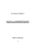

![OverView Control Manager user`s manual - operator [v04]](http://vs1.manualzilla.com/store/data/005659468_1-4c522981c7089838b286d7fbb1120c24-150x150.png)