1
4.3
Interpret the Output
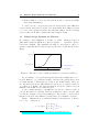
Health
good(2)
moderate(1)
bad(0)
02
01
00
absent(0)
12
11
10
present(0)
12
Intervention
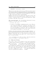
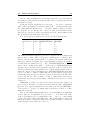
Table 1: The state space of the two dimensions Health and Intervention.
Each cell represents a point in this state space.
The numbers in the cells of the table show the “coordinates” within the
state space. The first digit of each number is the level of the first concept.
(“first” refers to the ordering of the concepts in the model view window).
The second digit is the level of the second concept, and so on. For example
the lower left cell has the number 00 which means it represents the situation
(the “state”) where intervention = 0 and health = 0. Similarly, the upper
right cell with the number 12 represents the state where intervention = 1
and health = 2. So this table shows all entries of the left part of the Kvalues table on the second tab (i.e. the entries of the truth table), but here
the cells are arranged on axes that represent a concept, each.
A cell, then, represents a state at time t. The arrow emanating from this
cell points to the state at the next step, t+1. This corresponds to the logical
function we defined in the K-values table. But there is one difference: in
Kinetic Logic, only one concept can change at a time. This means that there
are no diagonal arrows in the state table. Consider the 5th row in the Kvalue table: intervention = 1 and health = 1, and the output of the logical
functions for this input is IN T ERV EN T ION = 0 and HEALT H = 2.
In the state table (again on the dynamics tab), this would correspond to
an arrow from the middle right cell 11 to the upper left cell 02 if both
intervention and health could change at the same time (from 1 to 0 and
from 1 to 2, respectively). But this is not allowed. Instead, in the cell 11,
either intervention can change from 1 to 0, resulting in the new state 10,
or health can change from 1 to 2, resulting in the state 12. These two
possibilities are represented on the one hand by two arrows emanating from
the cell 11 and on the other hand by the tiny red minus resp. plus signs
above the digits of the cell number (− and + ): they indicate which concept is
going to change in the next step and into which direction. So the behavior of
the system can fork in this state. Which path it takes, is something beyond
the KLM: it cannot be modeled using Kinetic Logic.
A stable state is marked by inverted colors: a white number on a dark
background. Moreover, such a stable cell has no arrows emanating from it
and, accordingly, no minus or plus signs.
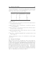
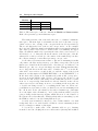
So let us try to make sense of the dynamics table we got: Starting
from the lower left cell (00), there is no intervention (absent) and health is