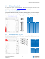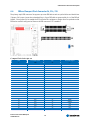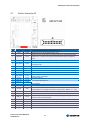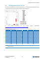
1
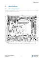
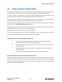
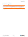
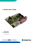
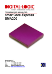
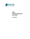
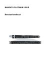
®
Kontron User’s Guide
®
ETXexpress miniBaseboard
Document Revision 1.12
This page intentionally left blank
Table of Contents
Table of Contents
1
User Information........................................................................................................ 5
1.1
1.2
1.3
1.4
1.5
1.6
2
About This Document .........................................................................................5
Copyright Notice ...............................................................................................5
Trademarks ......................................................................................................5
Standards ........................................................................................................5
Warranty .........................................................................................................5
Technical Support..............................................................................................6
Specifications ............................................................................................................ 7
2.1
2.2
2.2.1
2.2.2
Mechanical Specifications ...................................................................................7
Environmental Specifications ..............................................................................8
Temperature.....................................................................................................8
Humidity .........................................................................................................8
3
Short description........................................................................................................ 9
4
Block Diagram...........................................................................................................11
5
Connector locations ...................................................................................................12
6
Connector and feature description ...............................................................................14
6.1
6.2
6.3
6.4
6.5
6.6
6.7
6.8
6.9
6.10
6.11
6.12
6.13
6.14
6.15
6.16
Status LEDs .................................................................................................... 14
Power, Reset & PS_ON (SW1, SW2, J61, J62, J26) .................................................. 14
COM Express Connector J1................................................................................. 15
Power Connector J58, J59................................................................................. 15
SATA connector J3, J5, J33, J34......................................................................... 15
IDE and Compact Flash Connector J4, J14, J15...................................................... 16
Feature Connector J9 ....................................................................................... 17
Parallel and Serial Ports J6, J66, J67................................................................... 18
High Definition Audio J43, J46, J51, J71 ............................................................. 19
Ethernet J19 and configuration Jumper J20-24..................................................... 20
USB Ports J16, J65 .......................................................................................... 20
PCI and PCIexpress J10, J11 .............................................................................. 21
DVI and VGA Connector J8................................................................................. 21
TV-Out J2, J31 ................................................................................................ 22
Flat Panel Connector J55, J56............................................................................ 23
General Connectors ......................................................................................... 24
7
Express Card .............................................................................................................25
8
Battery Information...................................................................................................26
Kontron User's Guide ETXexpress
miniBaseboard
iii
Table of Contents
9
Limitations and installation hints ...............................................................................28
9.1
9.2
Known hardware restrictions ............................................................................. 28
Installation hints ............................................................................................ 28
10
Single Supply (without ATX) .......................................................................................29
11
Security advice..........................................................................................................30
12
Appendix A - Assembly Instruction: noATX Supply ..........................................................31
13
Appendix B - Power Distribution..................................................................................33
14
Document History......................................................................................................34
Kontron User's Guide ETXexpress
miniBaseboard
iv
1 0BUser Information
1
User Information
1.1
About This Document
This document provides information about products from Kontron Embedded Modules GmbH and/or its
subsidiaries. No warranty of suitability, purpose, or fitness is implied. While every attempt has been
made to ensure that the information in this document is accurate, the information contained within is
supplied “as-is” and is subject to change without notice.
For the circuits, descriptions and tables indicated, Kontron assumes no responsibility as far as patents or
other rights of third parties are concerned.
1.2
Copyright Notice
Copyright © 2007 Kontron Embedded Modules GmbH
All rights reserved. No part of this document may be reproduced, transmitted, transcribed, stored in a
retrieval system, or translated into any language or computer language, in any form or by any means
(electronic, mechanical, photocopying, recording, or otherwise), without the express written permission
of Kontron Embedded Modules GmbH.
DIMM-PC®, PISA®, ETX®, ETXexpress® , X-board®, DIMM-IO® and DIMM-BUS® are trademarks or
registered trademarks of Kontron Embedded Modules GmbH. Kontron is trademark or registered
trademark of Kontron AG.
1.3
Trademarks
The following lists the trademarks of components used in this board.
1.4
®
IBM, XT, AT, PS/2 and Personal System/2 are trademarks of International Business
Machines Corp.
®
Microsoft is a registered trademark of Microsoft Corp.
®
Intel is a registered trademark of Intel Corp.
®
All other products and trademarks mentioned in this manual are trademarks of their
respective owners.
Standards
Kontron Embedded Modules GmbH is certified to ISO 9000 standards.
1.5
Warranty
This Kontron Embedded Modules GmbH product is warranted against defects in material and
workmanship for the warranty period from the date of shipment. During the warranty period, Kontron
Embedded Modules GmbH will at its discretion decide to repair or replace defective products.
Within the warranty period, the repair of products is free of charge as long as warranty conditions are
observed.
Kontron User's Guide ETXexpress
miniBaseboard
5
1 0BUser Information
The warranty does not apply to defects resulting from improper or inadequate maintenance or handling
by the buyer, unauthorized modification or misuse, operation outside of the product’s environmental
specifications or improper installation or maintenance.
Kontron Embedded Modules GmbH will not be responsible for any defects or damages to other products
not supplied by Kontron Embedded Modules GmbH that are caused by a faulty Kontron Embedded
Modules GmbH product.
1.6
Technical Support
Technicians and engineers from Kontron Embedded Modules GmbH and/or its subsidiaries are available
for technical support. We are committed to making our product easy to use and will help you use our
products in your systems.
Please consult our Web site at http://www.kontron.com/support for the latest product documentation,
utilities, drivers and support contacts. In any case you can always contact your board supplier for
technical support.
Kontron User's Guide ETXexpress
miniBaseboard
6
2 1BSpecifications
2
Specifications
2.1
Mechanical Specifications
The ETXexpress miniBaseboard is 170mm x 145mm in size and the height is 41mm. See more detailed
mechanical specifications in the figure below:
Kontron User's Guide ETXexpress
miniBaseboard
7
2 1BSpecifications
2.2
Environmental Specifications
2.2.1
Temperature
Operating:
®
Ambient temperature: 0 to +60 °C
®
Non-operating: -30 to +85 °C
®
Ambient temperature: -25 to +85 °C
Storage:
Note:
2.2.2
The maximum operating temperature is the maximum measurable temperature on any spot on a baseboards’
surface. You must maintain the temperature according to the above specification.
Humidity
®
Operating: 10% to 90% (non condensing)
®
Non operating: 5% to 95% (non condensing)
Kontron User's Guide ETXexpress
miniBaseboard
8
3 2BShort description
3
Short description
The Kontron ETXexpress miniBaseboard is a COM Express evaluation backplane compatible to COM
Express Type 2 modules in basic and compact module size.
Product specifications:
®
Compatible to 10/100Mbit and GBit-Ethernet Modules
®
ATX EPS and Single Supply support
®
1 PCI Slot
®
1 PCIexpress x1 Slot
®
Express Card Slot
®
4 x SATA Ports
®
IDE (44pin) and Compact Flash Socket
®
LPT and 2 COM Ports
®
4 USB 2.0/1.1 Ports + 2 onboard USB pin header
®
Combined VGA/DVI and 2 x LVDS output
®
TV-Out: S-Video, component and composite
®
Onboard HD Audio Codec Realtek ALC888
®
Analog 7.1 Audio, optical and digital S/PDIF out + front Audio pin header
®
HW Monitor with 2 FAN and 3 Thermal DIODE connectors
®
Kontron Feature Connector
®
2nd Onboard Backup BIOS
®
Front Panel Connector (HDD Act, Reset SW, Power SW …)
Summary of all available interfaces:
Connector
BT3
J1
J2
J3
J4
J5
J6
J7
J8
J9
J10
J11
J12
J13
J14
Description
RTC Battery
COMexpress Connector
Component Video
SATA0
Primary IDE
SATA1
LPT
I/O Port (for internal use only)
DVI-I Connector
Kontron Feature Connector
PCI Connector
PCIexpress x1
VGA/DVI I2C Data Selector
VGA/DVI I2C Clock Selector
Compact Flash Socket
Kontron User's Guide ETXexpress
miniBaseboard
9
3 2BShort description
J15
J16
J17
J18
J19
J20
J21
J22
J23
J24
J25
J26
J31
J33
J34
J40
J41
J42
J43
J46
J49
J50
J51
J55
J56
J57
J58
J59
J60
J61
J62
J63
J65
J66
J67
J69
J70
J71
J72
SW1
SW2
CF Card Master/Single
USB Ports 0-3
HDD Activity LED
VGA/DVI DDC Power Selector
RJ-45 LAN Port
100MBit / GBit Ethernet Switch
Onboard SIO Adress Switch
ATX_PS_ON Override Jumper
TV-Out Composite/S-Video
SATA2
SATA3
Connector for external Temp Sensor 1
Connector for external Temp Sensor 2
Connector for external Temp Sensor 3
Front Panel Audio Connector
Digital Microphone In
FAN Connector 1
FAN Connector 2
7.1 Analog HD Audio Connector
JILI40 LVDS 1
JILI40 LVDS 2
Express Card Slot (on PCB’s back side)
ATX Main Power Connector
ATX_12V Power Connector
CPLD JTAG connector
Front Panel Reset Switch
Front Panel Power Swicth
Enable/Disable onboard Speaker
USB4 & USB6 Pin Header
COM1
COM2
Enable/Disable Module BIOS
Enable/Disable Status LEDs
Optical S/PDIF out connector (Toslink)
electrical S/PDIF out Pin header
Reset Button
Power Button
Kontron User's Guide ETXexpress
miniBaseboard
10
4 3BBlock Diagram
4
Block Diagram
Kontron User's Guide ETXexpress
miniBaseboard
11
5 4BConnector locations
5
Connector locations
Kontron User's Guide ETXexpress
miniBaseboard
12
5 4BConnector locations
(Layout L110)
Kontron User's Guide ETXexpress
miniBaseboard
13
6 5BConnector and feature description
6
Connector and feature description
6.1
Status LEDs
The onboard status and voltage indicator LEDs will show you the actual power state of the module and if
all voltages are working correctly.
LED
D85
D84
D83
D82
D104
D97
D96
D86
D88
D87
D89
D90
D94
D93
D91
D92
Description
S5 - Off State
S4 – Suspend to Disk
S3 – Suspend to RAM
Suspend
THRM – Temperature Alarm
Module Type2 not OK
12V / Battery (ATX_12V)
12V Voltage
5V Voltage
5V Standby Voltage
3.3V Voltage
3.3V Sil Voltage
3.3V No ATX / CPLD Voltage
2.5V Voltage
1.8V Voltage
1.5V Voltage
To reduce power consumption for example in battery driven systems open Jumper J70 to disable all
status LEDs.
6.2
Power, Reset & PS_ON (SW1, SW2, J61, J62, J26)
To configure the SW2 power button behavior refer to the BIOS section of the connected module.
PS_ON override J26
Jumper
Function
1-2
3-4
5-6
OFF
PS_ON
ON
Reset & Power Button
Connector
J61
SW1
J62
SW2
Function
Reset
Power
J62 (Power) and J61 (Reset) are pin header to connect a switch on the chassis front panel. With the
manual PS_ON override Jumper J26 you are able to switch the Power Supply on or off manually.
Kontron User's Guide ETXexpress
miniBaseboard
14
6 5BConnector and feature description
6.3
COM Express Connector J1
The standard COM Express connector follows the COM Express specifications. Please refer to the
specifications or module manuals on http://www.kontron.com for more details.
6.4
Power Connector J58, J59
Connect the ATX and the ATX_12V power supply cable to the power connector in the correct orientation.
The 12V power connector mainly supplies power to the module. If the 12V power connector is not
connected, the system will not start. For Single Supply without an ATX Power Supply please refer to
chapter Single Supply (without ATX).
6.5
Pin
Def
1
2
3
4
GND
GND
+12VDC
+12VDC
Pin
Def
Pin
Def
1
2
3
4
5
6
7
8
9
10
+3.3VDC
+3.3VDC
GND
+5VDC
GND
+5VDC
GND
PWR_OK
+5VSB
+12VDC
11
12
13
14
15
16
17
18
19
20
+3.3VDC
-12VDC
GND
PS_ON
GND
GND
GND
-5VDC
+5VDC
+5VDC
SATA connector J3, J5, J33, J34
The COM Express specification provides 4 SATA channels maximum. If all 4 SATA ports can be used
depends on the module specification.
Kontron User's Guide ETXexpress
miniBaseboard
15
SATA Pin
Signal
1
2
3
4
5
6
7
GND
TX+
TXGND
RXRX+
GND
Connector
SATA Port
J3
J5
J33
J34
SATA0
SATA1
SATA2
SATA3
6 5BConnector and feature description
6.6
IDE and Compact Flash Connector J4, J14, J15
The primary 44pin IDE connector J4 supports up to two IDE devices such as optical drives and hard drives
if jumper J15 is open. Locate the red marked line 1 of your IDE cable to connect with pin 1 of the IDE pin
header. Close jumper J15 to enable the CF Card Socket J14 as Master or Single drive. An optional second
IDE device must be configured as Slave on the IDE connector if CF is enabled.
Compact Flash Socket pin out
Pin
CF Socket Signal
Pin
CF Socket Signal
1
2
3
4
5
6
7
8
9
10
11
12
13
14
15
16
17
18
19
20
21
22
23
24
25
GND
D03
D04
D05
D05
D07
#CS0
GND
#ATA_SEL
GND
GND
GND
VCC +5V
GND
GND
GND
GND
A02
A01
A00
D00
D01
D02
n.c.
n.c.
26
27
28
29
30
31
32
33
34
35
36
37
38
39
40
41
42
43
44
45
46
47
48
49
50
n.c.
D11
D12
D13
D14
D15
#CS1
GND
#IOR
#IOW
#WE
INTRQ
VCC +5V
#CSEL
n.c.
#RESET
IORDY
#INPACK
#REG
#DASP
#PDIAG
D08
D09
D10
GND
Kontron User's Guide ETXexpress
miniBaseboard
16
6 5BConnector and feature description
6.7
Feature Connector J9
Pin
Signal Description
1
2
PWR_+5V
GPO2
5V power
3.3V-O
3
#BATLOW
3.3V-I
4
GPI2
3.3V-I
5
#SYS_RESET
3.3V-I
6
7
8
9
WDT
LPC_SERIRQ
I2C_DAT
3.3V-O
3.3V-I
3.3V-IO
10
#SMB_ALERT
3.3V-I
11
12
13
14
15
I2C_CLK
SMB_DAT
SMB_CLK
#WAKE1
3.3V-O
3.3V-IO
3.3V-O
3.3V-I
16
VCC_RTC
3V-I
17
18
#THRM
GND
3.3V-I
GND
19
PWR_OK
3.3V-I
20
21
22
23
24
GND
#PWRBTN
GND
#ATA_ACT
#CB_RESET
GND
3.3V-I
GND
3.3V-O
3.3V-O
Kontron User's Guide ETXexpress
miniBaseboard
+5V UL-protected with inductor (600R@100MHz, 1A)
General-purpose power management event output
Battery low input. May be driven low by external circuitry to signal that the system
battery is low, or may be used to signal some other external power management
event.
General-purpose power management event input
This input may be driven low by external circuitry in order to reset the power
management logic
Indicating that a Watchdog Timeout Event has occurred
Serial interrupt request. This pin is used to support the serial interrupt protocol.
Not connected
Data line of I2C-Bus
System Management Bus Alert input. May be driven low by SMB devices in order to
signal an event on the SM Bus
Clock line of I2C-Bus
Clock and data line of SM-Bus.
Not connected
Low driven general purpose wake-up signal
3V backup cell input. Should be connected to a 3V backup cell for RTC operation and
storage register non-volatility in the absence of system power. (VBATT = 2.4 – 3.3V)
Input from off-module temperature sensor indicating an over temperature situation
Ground
High active input indicating that power from the power supply is ready. It can also be
used as low active reset input signal.
Ground
Power Button Input. This input is used to support the ACPI Power Button function.
Ground
Low active output signal, which indicates activity on IDE interfaces.
Low active Reset output from module to carrier board
17
6 5BConnector and feature description
6.8
Parallel and Serial Ports J6, J66, J67
The ETXexpress miniBaseboard includes an external Super I/O Controller Winbond W83627HFJ with a
standard parallel port J6 and two serial ports COM1 (J66) and COM2 (J67).
For
serial
DSUB
connections
use
the
Kontron
http://emea.kontron.com/index.php?id=226&cat=56&productid=322
Adapter
KAB-DSUB9-3
LPT and COM Port pin out
Note:
Pin
LPT
COM1/COM2
Pin
LPT
COM1/COM2
1
3
5
7
9
11
13
15
17
19
21
23
25
#STB
PD0
PD1
PD2
PD3
PD4
PD5
PD6
PD7
#ACK
BUSY
PE
SLCT
DCD
RXD
TXD
DTR
GND
2
4
6
8
10
12
14
16
18
20
22
24
26
#AFD
#ERROR
#INIT
#SLCTIN
GND
GND
GND
GND
GND
GND
GND
GND
PWR_+5V
DSR
RTS
CTS
RI
NC
To use the legacy ports like COM and LPT a module with legacy BIOS is necessary to support the onboard
Winbond Super I/O
Kontron User's Guide ETXexpress
miniBaseboard
18
6 5BConnector and feature description
6.9
High Definition Audio J43, J46, J51, J71
The miniETXexpress Baseboard includes a Realtek ALC888 High Definition Audio Codec which supports up
to 7.1-channel speaker configuration, optical S/PDIF out and digital microphone input.
The optical Toslink S/PDIF Connector (J71), the coaxial S/PDIF Connector (J72) and the Front Panel
Audio Connector J43 provides digital audio out. J46 is used for digital microphone connection.
Pin
1
2
3
4
5
6
7
8
9
10
J43 – HD
MIC2-L
GND
MIC2-R (MIC Power)
PRESENCE#
LINE2-R (LineOut-R)
MIC2-JD
SENSE
Key Pin
Line2-L (LineOut-L)
LINE2-JD
J46
DMIC-CLK
DMIC-DATA
PWR_3.3V
GND
-
J72
SPDIF_OUT
GND
-
Speaker Configuration
J51
Orange
Black
Gray
Blue
Green
Pink
2-channel
Line In
Line Out
Mic In
4-channel
Rear Speaker
Line In
Front Speaker
Mic In
6-channel
Center/Subwoofer
Side Speaker
Line In
Front Speaker
Mic In
8-channel
Center/Subwoofer
Rear Speaker Out
Side Speaker Out
Line In
Front Speaker
Mic In
Note1: In addition to the default speaker settings, the analogue audio Jacks can be reconfigured to perform
different functions via the Realtek HDAudio Driver Software which is available on Kontron website. Only
microphones still must be connected to the default pink jack.
Note2: Audio is only working in combination with HD Audio compatible COM Express Modules.
Kontron User's Guide ETXexpress
miniBaseboard
19
6 5BConnector and feature description
6.10
Ethernet J19 and configuration Jumper J20-24
The Ethernet Port must be configured according to the modules specifications. For Gigabit Ethernet
modules close J20 – J24 (default). For a module with ONLY 10/100MBit connection open all Jumpers.
6.11
USB Ports J16, J65
COM Express defines a maximum of 8 USB Ports over module Type 2 connection. On ETXexpress
miniBaseboard 4 USB Ports (USB0-USB3) are provided via rear panel connector (J16) and two (USB4 &
USB6) ports via onboard pin header (J65). USB Port 5 is used for Express Card.
Note:
J65 Pin
Signal
1
3
5
7
9
VCC USB4
USB4USB4+
GND USB4
Key pin
2
4
6
8
10
VCC USB6
USB6USB6+
GND USB6
n.c.
If Express Card USB function and USB Port 6 can be used depends on the modules specification. For the
ExpressCard USB function a module with at least 6 USB ports is necessary. A module with 8 USB Ports will
support all USB features.
Kontron User's Guide ETXexpress
miniBaseboard
20
6 5BConnector and feature description
6.12
PCI and PCIexpress J10, J11
The miniETXexpress Baseboard provides one PCIexpress x1 slot (J11) connected to modules PCIexpress
Lane 3 and a standard PCI Slot. Please refer to the modules manual for more details.
6.13
DVI and VGA Connector J8
To connect a standard DVI or VGA Monitor use the combined DVI-I Single Link interface J8. An analog
CRT monitor can be used via an optional standard DVI-VGA Adapter. The DVI Interface is realized with a
Silicon Image SDVO to DVI Transmitter SIL1364 which uses the SDVO-B Channel from the COM Express
Module.
The standard Jumper configuration (J12 and J13) is for DVI DDC Data usage with 5V Bus Level Voltage
(see picture above). To enable VGA I2C connection short pin 1 and 2 of J12 and J13. To change the
Voltage Level on DDC I2C Bus to 3.3V short Pin 2 and 3 of Jumper J18.
Jumper Configuration
Pin
1
2
3
J12
VGA I2C Data
DDC Data
DVI DDC Data
Kontron User's Guide ETXexpress
miniBaseboard
J13
VGA I2C Clock
DDC Clock
DVI DDC Clock
21
J18
PWR_+5V
DDC Clock Pull Up
PWR_+3.3V
6 5BConnector and feature description
6.14
TV-Out J2, J31
The ETXexpress miniBaseboard provides three possible TV-Out connections. Composite Video (Yellow
Cinch) and S-Video out is available on the rear panel connector J31. Component TV-Out is available via
pin header J2. See the tables below for configuration details. For more details about TV-Out connection
refer to the modules manual.
J2 - Component TV Out
Pin
J2 Functi.
1
2
3
4
5
6
7
8
TV_DAC_A
GNDA
TV_DAC_B
GNDB
TV_DAC_C
GNDC
GNDA
NC
TV-Out configuration
Pin
TV_DAC_A
TV_DAC_B
TV_DAC_C
Composite Video
CVBS (composite)
-
Kontron User's Guide ETXexpress
miniBaseboard
S-Video
Y (Luminance)
C (Chrominance)
22
Component Video
Pb (Chrominance)
Luminance
Pr (Chrominance)
6 5BConnector and feature description
6.15
Flat Panel Connector J55, J56
The first LVDS display connection J55 is provided by the COM Express module. The second LVDS
connection is realized with a Chrontel CH7308B SDVOtoLVDS Transmitter which uses the modules SDVO-C
channel.
J55 and J56 LVDS pin out
Pin
1
2
3
4
5
6
7
8
9
10
11
12
13
14
15
16
17
18
19
20
Kontron User's Guide ETXexpress
miniBaseboard
LVDS Signal
NC
LCDDO0
LCDDO1
ENAVDD
LCDDO2
LCDDO3
NC
LCDDO4
LCDDO5
GND
LCDDO6
LCDDO7
GND
LCDDO8
LCDDO9
JILI_DAT
LCDDO10
LCDDO11
JILI_CLK
LCDDO12
Pin
21
22
23
24
25
26
27
28
29
30
31
32
33
34
35
36
37
38
39
40
23
LVDS Signal
LCDDO13
DETECT# (GND)
LCDDO14
LCDDO15
GND
LCDDO16
LCDDO17
GND
LCDDO18
LCDDO19
+5V
+5V
+5V
+5V
BLON#
GND
GND
+12V
+12V
+12V
6 5BConnector and feature description
6.16
General Connectors
The ETXexpress miniBaseboard provides an onboard backup BIOS and a CPLD. To enable booting from
this external BIOS short Jumper J69. To access the onboard CPLD via JTAG use J60.
With J40, J41 and J42 up to 3 external Temp Sensors can be connected to the onboard Winbond Super
I/O Controller. Open J63 to disable the onboard speaker.
CPLD JTAG Connector J60
Fan Connector J49, J50
Pin
Signal
Pin
Signal
1
2
3
Sense
+12V
GND
1
2
3
4
5
6
7
8
9
10
TCK
GND
TDO
+3,3V
TMS
NC
NC
NC
TDI
GND
Backup BIOS Disable J69
J69
Enable / Flash
Closed
Open
Backup BIOS
Module BIOS
SIO Address Switch J25
J25
Onboard SIO Adress
Closed
Open
4Eh
2Eh
Kontron User's Guide ETXexpress
miniBaseboard
24
7 6BExpress Card
7
Express Card
The onboard Express Card is connected to PCIexpress Lane0 and to USB Port5. To use the Express Card
USB functions a Module with at least 6 USB Ports is necessary.
The maximum continuous Card Power is
®
1,3A on 3,3V
®
275mA on Aux Power
®
650mA on 1,5V
Express Card pin out
Pin
1
2
3
4
5
6
7
8
9
10
11
12
13
Kontron User's Guide ETXexpress
miniBaseboard
Signal
GND
USB_DUSB_D+
CPUSB#
NC
NC
SMB_CLK
SMB_DATA
1.5V_2
1.5V_1
WAKE#
3.3VAUX
PERST#
Pin
14
15
16
17
18
19
20
21
22
23
24
25
26
25
Signal
3.3VS_1
3.3VS_0
CLKREQ#
CPPE#
REFCLKREFCLK+
GND
PERN0
PERP0
GND_1
PETN0
PETP0
GND_0
8 7BBattery Information
8
Battery Information
English:
CAUTION:
Danger of explosion if battery is incorrectly replaced. Replace only with the same or
equivalent type recommended by the manufacturer. Dispose of used batteries according to
the manufacturer’s instructions.
Deutsch:
VORSICHT:
Explosionsgefahr bei unsachgemäßem Austausch der Batterie. Ersatz nur durch denselben
oder einen vom Hersteller empfohlenen gleichwertigen Typ. Entsorgung gebrauchter
Batterien nach Angaben des Herstellers.
French:
ATTENTION:
Risque d‘explosion avec l‘échange inadéquat de la batterie. Remplacement seulement par le
même ou un type équivalent recommandé par le producteur. L’évacuation des batteries
usagées conformément à des indications du fabricant.
Danish:
ADVARSEL:
Lithiumbatteri – Eksplosionsfare ved fejlagtig Håndtering. Udskifting må kun ske med
batteri af samme fabrikant og type. Lever det brugte batteri tilbage til leverand ren.
Finnish:
VAROITUS:
Paristo voi rãjãhtãã, jos se on virheellisesti asennettu. Vaihda paristo
ainoastaanlaltevalmistajan suosittelmaan tyyppiln. Havita kaytetty paristo valmistajan
ohjeiden mukaisesti.
Spanish:
Kontron User's Guide ETXexpress
miniBaseboard
26
8 7BBattery Information
Precaución:
Peligro de explosión si la batería se sustituye incorrectamente. Sustituya solamente por el
mismo o tipo equivalente recomendado por el fabricante. Disponga las baterías usadas según
las instrucciones del fabricante.
Note:
The battery of this product is not considered to be accessible by the end user. Therefore the safety
instructions are only given in English, German, French, Danish, Finish and Spanish language.
If the battery of this product however is accessible by the end user, it is in the responsibility of the
Kontron customer to give the corresponding safety instructions in the required language(s).
Kontron User's Guide ETXexpress
miniBaseboard
27
9 8BLimitations and installation hints
9
Limitations and installation hints
9.1
Known hardware restrictions
Following restrictions are known in specified hardware revision.
PCB Layout L110 (CE 1.x.x, EFT Samples only):
®
No external LPC BIOS socket is available
®
No optical S/PDIF connector J71
®
Just 2 SATA Ports are working
®
FAN1 is always on 12V level (no PWM)
®
LPT Port is not available
®
Keyboard Reset is not working
®
USB pin header J65 has no standard pin assignment (USB+ & USB- crossed)
PCB Layout L111 (CE 2.2.0):
9.2
®
The orange and black analog audio jacks of J51 are exchanged
®
Some 2.5'' HDD on Primary IDE connector J4 are not working correctly when using in
UDMA5 mode
Installation hints
Please consider following information and installation hints:
Display connection during installation:
Possible module BIOS VGA Output Settings:
CRT:
enables the analog part of DVI connector J8
LFP:
enables the first LVDS connector J55
EFP:
enables the SDVO-B part and the digital part of DVI connector J8
The default display output in BIOS VGA settings for most ETXexpress modules is set to "CRT and LFP". In
this case it's necessary to use a CRT monitor with a DVI to CRT adapter on J8 or to use a LVDS panel on
J55/J56. If you change the BIOS settings to "LFP and EFP" or "CRT and EFP" to use a DVI panel, it's
possible that windows disables the DVI port during installation and you can't finish installation.
We recommend using a standard CRT Monitor via standard DVI-CRT adapter during installation to avoid
problems. After installation all devices can be activated in the driver options.
Kontron User's Guide ETXexpress
miniBaseboard
28
10 9BSingle Supply (without ATX)
10
Single Supply (without ATX)
The ETXexpress miniBaseboard is able to be supplied by just one voltage. This voltage have to be in the
range of 8.5V to 18V. This supply has to be connected at the 4pin ATX_12V power connector J59.
To use this feature it is as well necessary to have a module supporting the wide range input as some
small changes of the assembly (see below: Assembly Instructions to noATX supply).
Are these constraints fulfilled, the onboard regulators begin to do the supply instead of the ATX power
supply. But some restrictions have to be cared about in this single supply mode.
The onboard power regulators for 3.3V and 5V are limited to 6A each. After supplying the onboard
devices, there are 4.8A at 3.3V and 5.9A at 5V remaining.
Therefore the total current of the used external devices (PCI, PCIexpress, USB, LVDS panel, IDE/CF,
RS232/LPT) must not exceed these limits in single supply mode.
Additionally no PCI Card can be used, which needs -12V supply.
If a wide range power supply is used, the PCI and PCIexpress slots are not supplied with 12V. A LVDS
Display has to be supplied separately or with 5V and FAN2 is not supplied.
Assembly Instructions to noATX supply (see Apendix B)
®
Remove R710 (bottom) and mount R705 (100kOhm; bottom), R61 (210kOhm;
bottom) to ensure, that the CPLD is supplied correctly.
®
Remove R712 (bottom) and mount it on R711 (bottom), to switch the CPLD into the
single supply mode.
®
Remove J58 (top), to ensure, that there is no short with the onboard generated
voltages possible.
®
Mount R46 (0R; top) and R60 (210kOhm; bottom) to enable 5V Standby.
In the single supply mode there is a power save mode possible:
If R490 is removed and mounted on R491 (both on topside), the system will shut down after a short time
(about 8 seconds) in S5 completely. This means that nearly no power is used from the power supply,
because no device will supplied. But in this case it is only possible to wake up the system by pressing the
power button for at least one second.
Kontron User's Guide ETXexpress
miniBaseboard
29
11 10BSecurity advice
11
Security advice
To protect the external power lines to peripheral devices the customer has to take care about:
- The wires to the external device have the right diameter to withstand the max. available current
- The housing of the external device fulfils the fire protection requirements of IEC/EN 60950.
Kontron User's Guide ETXexpress
miniBaseboard
30
12 11BAppendix A - Assembly Instruction: noATX Supply
12
Appendix A - Assembly Instruction: noATX Supply
Kontron User's Guide ETXexpress
miniBaseboard
31
12 11BAppendix A - Assembly Instruction: noATX Supply
Kontron User's Guide ETXexpress
miniBaseboard
32
13 12BAppendix B - Power Distribution
13
Appendix B - Power Distribution
Kontron User's Guide ETXexpress
miniBaseboard
33
14 13BDocument History
14
Rev.
Document History
Date
Edited by
1.0_pre
1.0
27.11.2007
29.04.2008
PRO
PRO
1.1
05.05.2008
PRO
1.2
13.05.2008
PRO
Kontron User's Guide ETXexpress
miniBaseboard
Changes
Initial Release
Updated Audio section.
Added Chapter 9 - Limitations and installation hints, J65 USB Pin out table and
chapter 11 - Security Advice
Updated Limitations & Support Chapter
Corrected Feature Connector
34