1
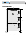
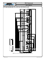
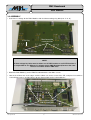
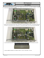
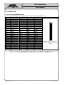
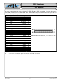
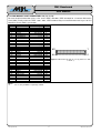
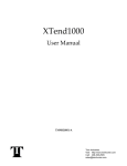
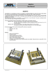
PMC Baseboard User Manual High-Tech • Made in Switzerland 2007 by MPL AG 1 MEH-10125-001 Rev. A PMC Baseboard User Manual High-Tech • Made in Switzerland TABLE OF CONTENTS 1 INTRODUCTION.............................................................................................................4 1.1 ABOUT THIS MANUAL...........................................................................................................4 1.2 SAFTY PRECAUTIONS AND HANDLING..............................................................................4 1.3 ELECTROSTATIC DISCHARGE (ESD) PROTECTION.........................................................4 1.4 EQUIPMENT SAFETY.............................................................................................................4 1.5 MANUAL REVISIONS.............................................................................................................5 1.5.1 RELATED PRODUCTS....................................................................................................5 1.5.2 REVISION HISTORY.......................................................................................................5 1.6 RELATED DOCUMENTATION................................................................................................6 1.7 ORDERING INFORMATION....................................................................................................6 2 SPECIFICATION.............................................................................................................7 2.1 ELECTRICAL...........................................................................................................................7 2.2 POWER....................................................................................................................................7 2.3 ENVIRONMENT.......................................................................................................................7 2.3.1 TEMPERATURE RANGE................................................................................................7 2.3.2 RELATIVE HUMIDITY......................................................................................................7 3 HARDWARE REFERENCE............................................................................................8 3.1 DIMENSIONS AND PLACEMENT...........................................................................................8 3.2 PMC BASEBOARD CUT-OUTS IN A PIP FRONT PLATE....................................................9 3.3 ASSEMBLY............................................................................................................................10 3.4 CONNECTORS......................................................................................................................12 3.4.1 PC/104-PLUS CONNECTOR (J8).................................................................................12 3.4.2 PMC MODULE SLOT CONNECTORS Jn1 (J1, J3, J5)................................................13 3.4.3 PMC MODULE SLOT CONNECTORS Jn2 (J2, J4, J6)................................................14 4 COPYRIGHT.................................................................................................................16 5 DISCLAIMER................................................................................................................16 6 TRADEMARKS.............................................................................................................16 7 SUPPORT.....................................................................................................................16 7.1 SERIAL NUMBER AND REVISION......................................................................................16 7.2 CONTACT MPL AG...............................................................................................................16 2007 by MPL AG 2 MEH-10125-001 Rev. A PMC Baseboard User Manual High-Tech • Made in Switzerland TABLE OF FIGURES Figure 1: Location Of The Mounting Holes And PMC Slot Holes............................................................................8 Figure 2: Front plate with the PMC Slot and the PIP10 connector cut-outs............................................................9 Figure 3: PC/104+ Connector (J8) (Connector: Samtec, PTHF-130-02-G-Q368)................................................12 Figure 4: PMC Connector Jn1 (J1, J3, J5) (Connector: AMP, 5120521-1)...........................................................13 Figure 5: PMC Connector Jn2 (J2, J4, J5) (Connector: AMP, 5120521-1)...........................................................14 2007 by MPL AG 3 MEH-10125-001 Rev. A PMC Baseboard User Manual High-Tech • Made in Switzerland 1 INTRODUCTION 1.1 ABOUT THIS MANUAL This manual provides all the information necessary to handle and configure the PMC Baseboard. The manual is written for technical personnel responsible for integrating the xxx into their systems. It is strongly recommended to read this manual before the PMC Baseboard is mounted into a PIP and is powered on. 1.2 SAFTY PRECAUTIONS AND HANDLING For personal safety and safe operation of the PMC Baseboard, follow all safety procedures described here and in other sections of the manual. ● Remove power from the system before installing (or removing) the PMC Baseboard, to prevent the possibility of personal injury (electrical shock) and / or damage to the product. ● Handle the product carefully; i.e. dropping or mishandling the PMC Baseboard can cause damage to assemblies and components. ● Do not expose the equipment to moisture. WARNING There are no user-serviceable components on the PMC Baseboard. 1.3 ELECTROSTATIC DISCHARGE (ESD) PROTECTION Various electrical components within the product are sensitive to static and electrostatic discharge (ESD). Even a small static discharge can be sufficient to destroy or degrade a component's operation! Do not touch any electronic components. Handle the PMC Baseboard only on the PCB edges. 1.4 EQUIPMENT SAFETY Great care is taken by MPL AG that all its products are thoroughly and rigorously tested before leaving the factory to ensure that they are fully operational and conform to specification. However, no matter how reliable a product, there is always the remote possibility that a defect may occur. The occurrence of a defect on this device may, under certain conditions, cause a defect to occur in adjoining and/or connected equipment. It is your responsibility to protect such equipment when installing this device. MPL accepts no responsibility whatsoever for such defects, however caused. 2007 by MPL AG 4 MEH-10125-001 Rev. A PMC Baseboard User Manual High-Tech • Made in Switzerland 1.5 MANUAL REVISIONS 1.5.1 RELATED PRODUCTS Manual Revisions A Related To • PIPPMC-1 Rev. A and later 1.5.2 REVISION HISTORY Manual Revisions A 2007 by MPL AG Date Description 2007-01-29 • Initial release of this document. 5 MEH-10125-001 Rev. A PMC Baseboard User Manual High-Tech • Made in Switzerland 1.6 RELATED DOCUMENTATION The following documents are related to this manual. For detailed Information about a PIP or for more information about a specific topic please refer to this additional manuals and specifications. Reference [1] [2] [3] [4] [5] [6] [7] [8] Description PIP BIOS User Manual PIP User Manual PIP Technical Reference Manual PCI2050b PCI-PCI Bridge data sheet PCI Local Bus Specification Rev. 2.2 PC/104-PLUS Specification, Rev. 2.0 IEEE 1386-2001, IEEE Standard for a Common Mezzanine Card (CMC) Family IEEE 1386.1-2001, IEEE Standard Physical and Environmental Layers for PCI Mezzanine Cards (PMC) Available from MPL AG: www.mpl.ch MPL AG: www.mpl.ch MPL AG: www.mpl.ch Texas Instruments: www.ti.com PCI-SIG: www.pcisig.com PC/104 Embedded Consortium: www.pc104.org IEEE Standards Association: standards.ieee.org IEEE Standards Association: standards.ieee.org 1.7 ORDERING INFORMATION The table below gives you an overview of the different PMC Baseboard variants and its features. Product Name PIPPMC-1 Rev. A 2007 by MPL AG Product Features • Support for up to 3 PMC Modules on PC/104-PLUS slot 0 • Selectable VIO voltage via distance piece • −40 °C to +85 °C • RoHS compliant There are also options available for: • +/- 12 V on board support Please contact MPL AG for further information. 6 MEH-10125-001 Rev. A PMC Baseboard User Manual High-Tech • Made in Switzerland 2 SPECIFICATION 2.1 ELECTRICAL • • • • • 32 Bit / 33 MHz PCI Bus on PC/104-PLUS interface 32 Bit / 33 MHz PCI Bus on PMC interface connectors Jn1 and Jn2 Supports up to 3 PMC Modules Texas Instruments PCI2050B PCI-PCI Bridge Supports +/- 12 V on board (optional) 2.2 POWER • 3.3 V, 5 V and VIO current support is depending on the current supported via the PC/104-PLUS connector. • Optional +/- 12 V voltages support, depending on the ordered option, either +/- 250 mA for all three PMC Slots or +/- 250 mA for each of the three PMC Slots. 2.3 ENVIRONMENT 2.3.1 TEMPERATURE RANGE • −40 °C to +85 °C (-40 °F to +185 °F) 2.3.2 RELATIVE HUMIDITY • 10% to 90% non-condensing 2007 by MPL AG 7 MEH-10125-001 Rev. A PMC Baseboard User Manual High-Tech • Made in Switzerland 3 HARDWARE REFERENCE 3.1 DIMENSIONS AND PLACEMENT 153.5mm. 64 63 1 2 254.0mm. 64 63 107.0mm. 89.8mm. 64 63 6.2mm. 14.8mm. 5.0mm. 27.8mm. 15.0mm. 164.8mm. 2 1 2 J2 64 0.8mm. 5V-KEY 63 3.3V-KEY 34.0mm. J1 34.0mm. 1 16.0mm. SLOT 1 69.5mm. 2 1 2 J6 64 64 J4 2 5V-KEY 63 5V-KEY 3.3V-KEY SLOT 2 63 J3 1 3.3V-KEY SLOT 3 J5 30 1 J8 1 1 2 O N ABCD S1=OFF/S2=OFF: MODULE=1, OFF/ON: 2, ON/OFF: 3, ON/ON: 4 264.0mm. 10.5mm. 11.7mm. 130.1mm. Figure 1: Location Of The Mounting Holes And PMC Slot Holes 2007 by MPL AG 8 MEH-10125-001 Rev. A 4.50 18.70 11.70 50.45 265.0 105.50 89.24 72.99 49.56 20.66 239.58 210.75 205.70 188.10 161.36 141.56 135.75 121.77 60.75 RJ45 17.55 72.1 0 A USB USB 14.30 9.00 13.5 0 R 0,6 (8x) R 2.5 (2x) R 0,6 (2x) A 25.00 DVI-I 16.70 9 R 0,5 (3x 2x) 1394b 11.51 (3x) Ø 3.0 (2 x) 8.86 2007 by MPL AG 1394b R 0,6 (3 x 4x) A 1394b R 0,5 (3x 2x) 1.00 (3x) 3.00 (3x) 13.00 13.00 A 26.13 High-Tech • Made in Switzerland 16.33 R 3.25 PMC Baseboard User Manual 3.2 PMC BASEBOARD CUT-OUTS IN A PIP FRONT PLATE Figure 2: Front plate with the PMC Slot and the PIP10 connector cut-outs MEH-10125-001 Rev. A 15.33 7.75 18.20 15.85 24.35 6.12 6.12 14.00 69.90 PMC Baseboard User Manual High-Tech • Made in Switzerland 3.3 ASSEMBLY • Select the VIO voltage for the PMC Modules with the leftmost voltage key bolt (near J1 or J2). 3.3V Key Must be on the same position 5.0V Key NOTE: All three voltage key bolts must be either at 3.3V-KEY location or at 5V-KEY location. It is not possible to use different VIO voltages on the PMC Baseboard, because the same PCI bus is used for all three PMC slots. • Mount the PMC Module(s) on the PMC Baseboard with the four M2.5 screws. • Loosen the 4 M2.5 nuts at the edges and the 2 M2.5 nuts on the center of the PIP, and place instead the 6 1.5mm distance pieces and the M2.5 x 30 mm distance bolts on the 6 threaded pins. 6x distance pieces and distance bolts 2007 by MPL AG 10 MEH-10125-001 Rev. A PMC Baseboard User Manual High-Tech • Made in Switzerland • Connect all needed cables, memory or other modules to the PIP PCB. If the PMC Baseboard is installed, there is no way to reach the PIP PCB. • Either install a PC/104-PLUS (PC/104 is not possible) card and fix it with three M3 x 15 mm distance bolts or place three 1.5mm distance pieces and the M3 x 15 mm distance bolts on the PC/104-PLUS mounting bolts. 3x distance pieces and distance bolts • If no PC/104-PLUS card is used place the distance connector to the PC/104-PLUS connector on the PIP. Distance connector with shroud • Install the PMC Baseboard an fix it with three M3 x 6 screws an four M2.5 x 6 screws. 2007 by MPL AG 11 MEH-10125-001 Rev. A PMC Baseboard User Manual High-Tech • Made in Switzerland 3.4 CONNECTORS 3.4.1 PC/104-PLUS CONNECTOR (J8) For more detailed information please refer to the PC/104-PLUS Specification, Rev. 2.0. Number 1 2 3 4 5 6 7 8 9 10 11 12 13 14 15 16 17 18 19 20 21 22 23 24 25 26 27 28 29 30 Row A GND VIO AD5 C/BE0 GND AD11 AD14 +3.3 V SERR GND STOP +3.3 V FRAME GND AD18 AD21 +3.3 V IDSEL0 AD24 GND AD29 +5 V REQ0 GND GNT1 +5 V CLK2 GND NC (+12 V)*1 NC (–12 V)*1 Row B NC AD2 GND AD7 AD9 VIO AD13 C/BE1 GND PERR +3.3 V TRDY GND AD16 +3.3 V AD20 AD23 GND C/BE3 AD26 +5 V AD30 GND REQ2 VIO CLK0 +5 V INTD INTA REQ3 Row C +5 V AD1 AD4 GND AD8 AD10 GND AD15 NC +3.3 V LOCK GND IRDY +3.3 V AD17 GND AD22 IDSEL1 VIO AD25 AD28 GND REQ1 +5 V GNT2 GND CLK3 +5 V INTB GNT3 Row D AD0 +5 V AD3 AD6 M66EN GND AD12 +3.3 V PAR NC GND DEVSEL +3.3 V C/BE2 GND AD19 +3.3 V IDSEL2 IDSEL3 GND AD27 AD31 VIO GNT0 GND CLK1 GND RST INTC GND Pin Assignment ABCD 1 30 Figure 3: PC/104+ Connector (J8) (Connector: Samtec, PTHF-130-02-GQ368) Notes: *1 +/–12 V is not connected on the PMC Baseboard, because on PIP Hardware normally the +/–12 V are not supported. +/–12 V for the PMC Module slots are generated on PMC Baseboard if separately ordered. 2007 by MPL AG 12 MEH-10125-001 Rev. A PMC Baseboard User Manual High-Tech • Made in Switzerland 3.4.2 PMC MODULE SLOT CONNECTORS Jn1 (J1, J3, J5) For more detailed information please refer to the IEEE 1386-2001, IEEE Standard for a Common Mezzanine Card (CMC) Family and to the IEEE 1386.1-2001, IEEE Standard Physical and Environmental Layers for PCI Mezzanine Cards (PMC) specification. Pn1/Jn1 32-bit PCI Pin Signal 1 3 5 7 9 11 13 15 17 19 21 23 25 27 29 31 33 35 37 39 41 43 45 47 49 51 53 55 57 59 61 63 TCK Ground INTB# BUSMODE1# INTD# Ground CLK Ground REQ# VIO AD[28] AD[25] Ground AD[22] AD[19] VIO FRAME# Ground DEVSEL# Ground PCI-RSVD* PAR VIO AD[12] AD[09] Ground AD[06] AD[04] VIO AD[02] AD[00] Ground Signal Pin –12 V*1 INTA# INTC# +5 V PCI-RSVD* NC (3.3 VAUX)*2 Ground GNT# +5 V AD[31] AD[27] Ground C/BE[3]# AD[21] +5 V AD[17] Ground IRDY# +5 V LOCK# PCI-RSVD* Ground AD[15] AD[11] +5 V C/BE[0]# AD[05] Ground AD[03] AD[01] +5 V REQ64# 2 4 6 8 10 12 14 16 18 20 22 24 26 28 30 32 34 36 38 40 42 44 46 48 50 52 54 56 58 60 62 64 63 1 64 2 Figure 4: PMC Connector Jn1 (J1, J3, J5) (Connector: AMP, 5120521-1) Notes: *1 –12 V is only available if separately ordered. *2 3.3 VAUX is not supported, this pin is not connected on the PMC Baseboard. 2007 by MPL AG 13 MEH-10125-001 Rev. A PMC Baseboard User Manual High-Tech • Made in Switzerland 3.4.3 PMC MODULE SLOT CONNECTORS Jn2 (J2, J4, J6) For more detailed information please refer to the IEEE 1386-2001, IEEE Standard for a Common Mezzanine Card (CMC) Family and to the IEEE 1386.1-2001, IEEE Standard Physical and Environmental Layers for PCI Mezzanine Cards (PMC) specification. Pin 1 3 5 7 9 11 13 15 17 19 21 23 25 27 29 31 33 35 37 39 41 43 45 47 49 51 53 55 57 59 61 63 Jn2/Pn2 32-bit PCI Signal Signal +12 V*1 TRST# TMS TDO TDI Ground Ground PCI-RSVD* PCI-RSVD* PCI-RSVD* BUSMODE2# +3.3 V RST# BUSMODE3# 3.3 V BUSMODE4# PME# Ground AD[30] AD[29] Ground AD[26] AD[24] +3.3 V IDSEL AD[23] +3.3 V AD[20] AD[18] Ground AD[16] C/BE[2]# Ground PMC-RSVD TRDY# +3.3 V Ground STOP# PERR# Ground +3.3 V SERR# C/BE[1]# Ground AD[14] AD[13] M66EN AD[10] AD[08] +3.3 V AD[07] PMC-RSVD +3.3 V PMC-RSVD PMC-RSVD Ground PMC-RSVD PMC-RSVD Ground PMC-RSVD ACK64# +3.3 V Ground PMC-RSVD Pin 2 4 6 8 10 12 14 16 18 20 22 24 26 28 30 32 34 36 38 40 42 44 46 48 50 52 54 56 58 60 62 64 63 1 64 2 Figure 5: PMC Connector Jn2 (J2, J4, J5) (Connector: AMP, 5120521-1) Notes: *1 +12 V is only available if separately ordered. 2007 by MPL AG 14 MEH-10125-001 Rev. A PMC Baseboard User Manual High-Tech • Made in Switzerland This page is intentionally left blank. 2007 by MPL AG 15 MEH-10125-001 Rev. A PMC Baseboard User Manual High-Tech • Made in Switzerland 4 COPYRIGHT Copyright © 2007 by MPL AG Elektronikunternehmen. All rights are reserved. Reproduction of this document in part or whole, by any means is prohibited, without written permission from MPL AG Elektronikunternehmen. 5 DISCLAIMER MPL AG has fully tested the PMC Baseboard and reviewed the documentation. However, MPL AG makes no warranty or representation, either expressed, or implied, with respect to this product, its quality, performance, merchantability, or fitness for a particular purpose. In no event will MPL AG be liable for direct, indirect, special, incidental, or consequential damages resulting from any defect in the product or its documentation, even if advised of the possibility of such damages. In particular MPL AG shall have no liability for any parts connected to this product. MPL AG reserves the right to make changes to any product herein to improve reliability, function or design. 6 TRADEMARKS Brand or product names are trademarks and registered trademarks of their respective holders. 7 SUPPORT 7.1 SERIAL NUMBER AND REVISION For support it is needed that you know the product name, the product variant and the serial number of your PMC Baseboard. Please have a look at the label on the PCB of the PMC Baseboard for this. 7.2 CONTACT MPL AG In case of general information questions please feel free to contact us at our homepage (www.mpl.ch) or per email ([email protected]). In case of sales information questions please send an email to [email protected]. If you have a technical problem with a PMC Baseboard, first please read carefully all the manuals mentioned in the section 1.6 RELATED DOCUMENTATION. If you can’t solve the problem on your own you can contact us for technical support per email at [email protected]. Our local Distributor: 2007 by MPL AG 16 MEH-10125-001 Rev. A