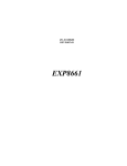
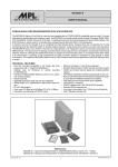
1
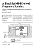
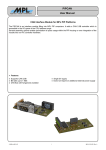
SPIDERLAN
USER MANUAL
PC/104-PLUS 4 / 8 PORT FAST ETHERNET SWITCH MODULE
The SPIDERLAN-family consists of universal high performance, compact and robust ethernet modules for
the industrial use. SPIDERLAN unifies two complete 10/100BaseTX Fast Ethernet Adapters on a single
PC/104-plus board. Each network controller is combined with a integrated 5 port layer-2 switch subsystem.
So the board comes with up to eight (2x4) fully independent operating external 10/100BASE-TX ports, all
available on RJ45 connectors. Switched networking minimizes network loading, eliminates collisions and
enables true deterministic communications. SPIDERLAN is available as compact single PC/104-Plus module
with connectors onboard, or with separated switch sub-modules for front panel assemblies. All these features
make SPIDERLAN to the ideal solution for industrial network applications, like routers, firewalls, etc.
Features
·
·
·
·
·
·
·
·
·
·
·
TM
Up to 2 AMD PCNet Fast –III Fast Ethernet controllers on a single board
High performance bus mastering for low CPU and bus utilisation.
PCI specification 2.2 compliant
5 volt only power supply
up to 2 integrated 5-port layer-2 ethernet switch subsystems
up to 8 (2x4) external 10/100BaseTX ports
onboard RJ45 connectors, or separated external switch sub-modules
IEEE: 802.3u autonegotiation 10/100 Mbps, half/full duplex operation
Full duplex IEEE: 802.3x support
MDI / MDI-X autocrossover functionality
2 LED indicators for all ports
Ó2002 by MPL AG
1
MEH-10095-001 Rev. B
SPIDERLAN
USER MANUAL
TABLE OF CONTENTS
1.
1.1
1.2
1.3
1.4
2.
INTRODUCTION ............................................................................................................................................. 4
ABOUT THIS MANUAL.............................................................................................................................. 4
SAFETY PRECAUTIONS AND HANDLING .............................................................................................. 4
ELECTROSTATIC DISCHARGE (ESD) PROTECTION ........................................................................... 4
EQUIPMENT SAFETY ............................................................................................................................... 4
GENERAL INFORMATION AND SPECIFICATIONS ..................................................................................... 5
2.1 SPECIFICATIONS...................................................................................................................................... 5
PHYSICAL/POWER........................................................................................................................................... 6
2.2 VERSION INFORMATION ......................................................................................................................... 6
2.3 DIMENSIONS............................................................................................................................................. 7
2.3.1
EXTERNAL SWITCH VERSION (SPIDERLAN-1E, SPIDERLAN-2E) ............................................. 7
2.3.1.1
BASEBOARD ................................................................................................................................ 7
2.3.1.2
SWITCH SUBMODULE (SPIMS4)................................................................................................ 8
2.3.2
ONBOARD SWITCH VERSION (SPIDERLAN-1P, SPIDERLAN-2P) .............................................. 9
3.
PREPARATION FOR USE............................................................................................................................ 10
3.1 PARTS LOCATION .................................................................................................................................. 10
3.1.1
EXTERNAL SWITCH VERSION (SPIDERLAN-1E, SPIDERLAN-2E) ........................................... 10
3.1.1.1
BASEBOARD .............................................................................................................................. 10
3.1.1.2
SWITCH SUBMODULE (SPIMS4).............................................................................................. 11
3.1.1.3
ONBOARD SWITCH VERSION (SPIDERLAN-1P, SPIDERLAN-2P)........................................ 12
3.2 SWITCH SETTINGS ................................................................................................................................ 13
3.2.1
PC/104-PLUS SLOT SELECTOR SWITCH.................................................................................... 13
3.2.1.1
PC/104-PLUS MODULE STACK ................................................................................................ 13
3.2.1.2
SINGLE CHANNEL VERSION (SPIDERLAN-1P, SPIDERLAN-1E).......................................... 13
3.2.1.3
DUAL CHANNEL VERSION (SPIDERLAN-2P, SPIDERLAN-2E) ............................................. 13
3.3 CONNECTORS ........................................................................................................................................ 14
3.3.1
CONNECTOR FOR SPIMS-4 MODULE (SPIDERLAN-1E, SPIDERLAN-2E) ............................... 14
3.3.2
QUAD RJ45 – CONNECTORS ....................................................................................................... 15
3.3.3
PC/104 INTERFACE PIN NUMBERS ............................................................................................. 16
3.3.4
PC/104 PLUS INTERFACE PIN NUMBERS................................................................................... 17
4.
OPERATION ................................................................................................................................................. 18
4.1 BLOCK DIAGRAM.................................................................................................................................... 18
4.1.1
ONBOARD SWITCH VERSION (SPIDERLAN-1P, SPIDERLAN-2P) ............................................ 18
4.1.2
EXTERNAL SWITCH VERSION (SPIDERLAN-1E, SPIDERLAN-2E) ........................................... 19
4.2 LED INDICATORS ................................................................................................................................... 20
4.2.1
INTEGRATED RJ45 CONNECTOR INDICATORS ........................................................................ 20
4.2.1.1
LINK / ACTIVITY (GREEN)......................................................................................................... 20
4.2.1.2
10/100 MBIT (YELLOW) ............................................................................................................. 20
4.2.2
EXTERNAL SWITCH VERSION (SPIDERLAN-1E, SPIDERLAN-2E) ........................................... 20
4.2.2.1
LED5 - TRANSMIT ACTIVITY .................................................................................................... 20
4.2.2.2
LED6 - RECEIVE ACTIVITY....................................................................................................... 20
4.3 5-PORT LAYER 2 SWITCH SUBSYSTEM.............................................................................................. 21
4.3.1
ADVANTAGES OF SWITCHED NETWORKING............................................................................ 21
4.3.2
ADDRESS LOOK UP ...................................................................................................................... 21
4.3.2.1
LEARNING .................................................................................................................................. 21
4.3.2.2
MIGRATION ................................................................................................................................ 21
4.3.2.3
AGING......................................................................................................................................... 21
4.3.2.4
FORWARDING ........................................................................................................................... 22
4.3.3
SWITCHING ENGINE ..................................................................................................................... 22
Ó 2002 by MPL AG
2
MEH-10095-001 Rev. B
SPIDERLAN
USER MANUAL
4.3.4
MAC OPERATION .......................................................................................................................... 22
4.3.4.1
INTER PACKET GAP (IPG)........................................................................................................ 22
4.3.4.2
BACKOFF ALGORITHM............................................................................................................. 22
4.3.4.3
LATE COLLISION ....................................................................................................................... 22
4.3.4.4
ILLEAGAL FRAMES ................................................................................................................... 22
4.3.4.5
FLOW CONTROL ....................................................................................................................... 23
4.3.4.6
HALF DUPLEX BACK PRESSURE ............................................................................................ 23
4.3.5
BROADCAST STORM PROTECTION ........................................................................................... 23
4.3.6
AUTO NEGOTIATION..................................................................................................................... 23
5.
SOFTWARE .................................................................................................................................................. 24
5.1 DEVICE DRIVERS ................................................................................................................................... 24
5.1.1
LINKS TO THE LATEST DRIVERS ................................................................................................ 24
6.
6.1
6.2
SUPPORT INFORMATION ........................................................................................................................... 25
MPL AG .................................................................................................................................................... 25
PRODUCTION SERIAL AND REVISION NUMBER................................................................................ 25
Ó 2002 by MPL AG
3
MEH-10095-001 Rev. B
SPIDERLAN
USER MANUAL
1. INTRODUCTION
1.1 ABOUT THIS MANUAL
This manual assists the installation and initialisation procedure by providing all the information necessary to
handle and configure the SPIDERLAN.
The manual is written for technical personnel responsible for integrating the SPIDERLAN into their system.
1.2 SAFETY PRECAUTIONS AND HANDLING
For personal safety and safe operation of the SPIDERLAN, follow all safety procedures described here and
in other sections of the manual.
· Power must be removed from the system before installing (or removing) the SPIDERLAN to prevent the
possibility of personal injury (electrical shock) and/or damage to the product.
· Handle the product carefully, i.e., dropping or mishandling the SPIDERLAN can cause damage to
assemblies and components.
· Do not expose the equipment to moisture.
WARNING
There are no user-serviceable components on the SPIDERLAN
1.3 ELECTROSTATIC DISCHARGE (ESD) PROTECTION
Various electrical components within the product are sensitive to static and electrostatic discharge (ESD).
Even a non-sensible static discharge can be sufficient to destroy or degrade a component's operation!
With an open housing, do not touch any electronic components. Handle or touch only the unit chassis.
1.4 EQUIPMENT SAFETY
Great care is taken by MPL that all its products are thoroughly and rigorously tested before leaving the
factory to ensure that they are fully operational and conform to specification. However, no matter how reliable
a product, there is always the remote possibility that a defect may occur. The occurrence of a defect on this
device may, under certain conditions, cause a defect to occur in adjoining and/or connected equipment. It is
the user’s responsibility to ensure that adequate protection for such equipment is incorporated when
installing this device. MPL accepts no responsibility whatsoever for such kind of defects, however caused.
Ó 2002 by MPL AG
4
MEH-10095-001 Rev. B
SPIDERLAN
USER MANUAL
2. GENERAL INFORMATION AND SPECIFICATIONS
This chapter provides a general overview over the SPIDERLAN and its features. It outlines the electrical and
physical specifications of the product, its power requirements and a list of related publications.
2.1 SPECIFICATIONS
ELECTRICAL
Ethernet Controller:
TM
· single/dual AMD PCNet FAST III ethernet controllers
· 32-bit PCI bus master
· supports 3.3V and 5V PCI signalling
· DMA buffer management unit for low CPU and bus utilisation
· Large independent RX/TX FIFO buffers
· IEEE802.3 and Blue book ethernet compatible
· Device drivers for all major operation systems available
Ethernet Switch:
· single/dual Kendin KS8995E layer-2 ethernet switch chipset
· 1 internal port, (connected to onboard ethernet controller)
· 4 external 10/100BaseTX ports
· 128 kB SRAM for frame buffering
· 1.4Gps high performance memory bandwidth
· Lookup engine supports 1k absolute MAC addresses
· Automatic address learning, aging and migration
· Broadcast storm protection
Physical:
· Hardware based 10/100, full/half, flow control and autonegotiation
· Full duplex IEEE802.3x flow control
· Half duplex back pressure flow control
Connectors:
· single/dual onboard quad-RJ45 connectors or optionally 40 pin mini headers
for the connection of external switch sub-modules
Indicators:
· indicators for link status / activity and 10/100 Mbps operation (for each port)
Ó 2002 by MPL AG
5
MEH-10095-001 Rev. B
SPIDERLAN
USER MANUAL
PHYSICAL/POWER
Form factor:
Length x width x height : 95.89 mm (3.775’’) x 90.17 mm (3.550’’) x 13.5 mm max.
(please refer to section 2.2)
Weight:
120g / 0.265lbs (fully equipped SPIDERLAN-2P)
Input Power :
+5VDC +- 5%
Power consumption:
Typ. 2.5W (single controller, 4ports) / 5W (dual controller, 8 ports)
ENVIRONMENT
Temperature range:
0°C to +70°C (+32°F to +158°F)
optional -40°C to +75°C (-40°F to +185°F)
Relative humidity:
10% ... 90% non condensing
2.2 VERSION INFORMATION
SPIDERLAN-1P:
SPIDERLAN-2P:
SPIDERLAN-1E:
SPIDERLAN-2E:
Ó 2002 by MPL AG
single ethernet controller with onboard switch subsystem,
dual ethernet controllers, each with onboard switch subsystem
single ethernet controller with separated switch sub-module
dual ethernet controllers with two separated switch sub-modules
6
MEH-10095-001 Rev. B
SPIDERLAN
USER MANUAL
2.3 DIMENSIONS
2.3.1 EXTERNAL SWITCH VERSION (SPIDERLAN-1E, SPIDERLAN-2E)
11.12
2.3.1.1 BASEBOARD
+
7.62
11.12
85.09
81.28
90.17
1
2
O
N
+
5.08
5.08
34.25
38.99
46.10
53.21
59.75
60.33
90.81
Ó 2002 by MPL AG
10.64
10.60
9.35
6.00
11.45
95.89
7
MEH-10095-001 Rev. B
SPIDERLAN
USER MANUAL
2.3.1.2 SWITCH SUBMODULE (SPIMS4)
4.34
4.60
24.38
29.85
4.34
1.60
2.50
13.49
+
25.78
30.19
45.16
70.66
88.41
92.84
96.52
Ó 2002 by MPL AG
8
MEH-10095-001 Rev. B
SPIDERLAN
USER MANUAL
2.3.2 ONBOARD SWITCH VERSION (SPIDERLAN-1P, SPIDERLAN-2P)
+
90.17
85.09
81.28
7.62
5.08
1
2
O
N
+
+
Ó 2002 by MPL AG
9
10.64
1.60
3.40
10.60
9.35
11.45
13.49
5.08
22.63
80.85
90.81
95.89
MEH-10095-001 Rev. B
SPIDERLAN
USER MANUAL
3. PREPARATION FOR USE
3.1 PARTS LOCATION
3.1.1 EXTERNAL SWITCH VERSION (SPIDERLAN-1E, SPIDERLAN-2E)
3.1.1.1 BASEBOARD
PC/104
connector
PC/104-Plus
connector
LED6 LED5
Channel 2
LED6
LED5
AB
1
39
40
1
2
ABCD
1
SPIMS4 submodule connector
DC
0
+
PC/104
connector
PC/104-Plus
connector
1
2
O
N
+
PC/104-Plus
Slot Selector Switch
2
1
40
39
30
32
SPIMS4 submodule connector
LED5
LED6
PC/104
connector
Channel 1
PC/104-Plus
connector
LED5 LED6
Ó 2002 by MPL AG
10
MEH-10095-001 Rev. B
SPIDERLAN
USER MANUAL
3.1.1.2 SWITCH SUBMODULE (SPIMS4)
LED1-2
LED1-1
LED2-2
LED2-1
LED3-2
LED3-1
LED4-2
LED4-1
+
8
1 8
Port 1
1 8
Port 2
1 8
Port 3
1
Port 4
4x 10/100BaseTX, RJ45
2
1
40
39
SPIMS4 submodule connector
Ó 2002 by MPL AG
11
MEH-10095-001 Rev. B
SPIDERLAN
USER MANUAL
3.1.1.3 ONBOARD SWITCH VERSION (SPIDERLAN-1P, SPIDERLAN-2P)
LED1-2
PC/104-Plus
connector
LED1-1
LED2-2
LED2-1
LED3-2
LED3-1
LED4-2
LED4-1
PC/104
connector
+
8
1 8
Port 1
1 8
Port 2
1 8
Port 3
1
Port 4
Channel 2
AB
1
4x 10/100BaseTX, RJ45
factory
used
1
ABCD
DC
PC/104
connector
0
PC/104-Plus
connector
+
+
1
2
O
N
PC/104-Plus
Slot Selector Switch
30
4x 10/100BaseTX, RJ45
32
Channel 1
PC/104
connector
LED1-2
LED1-1
LED2-2
LED2-1
LED3-2
LED3-1
LED4-2
LED4-1
PC/104-Plus
connector
+
8
1 8
Port 1
Ó 2002 by MPL AG
1 8
Port 2
1 8
Port 3
12
1
Port 4
MEH-10095-001 Rev. B
SPIDERLAN
USER MANUAL
O
N
3.2 SWITCH SETTINGS
1
2
Default switch settings are in brackets.
3.2.1 PC/104-PLUS SLOT SELECTOR SWITCH
3.2.1.1 PC/104-PLUS MODULE STACK
Module Slot 4
Module Slot 3
Module Slot 2
Module Slot 1
Baseboard
3.2.1.2 SINGLE CHANNEL VERSION (SPIDERLAN-1P, SPIDERLAN-1E)
SW1-1
(OFF)
OFF
ON
ON
SW1-2
(OFF)
ON
OFF
ON
Ethernet Controller 1
Module Slot 1
Module Slot 2
Module Slot 3
Module Slot 4
3.2.1.3 DUAL CHANNEL VERSION (SPIDERLAN-2P, SPIDERLAN-2E)
SPIDERLAN versions, which have 2 network controllers, behave like 2 independent PC-104-plus cards.
Two module slots in the PC-104-plus stack will be occupied.
SW1-1
(OFF)
OFF
ON
ON
Ó 2002 by MPL AG
SW1-2
(OFF)
ON
OFF
ON
Ethernet Controller 1
Module Slot 1
Module Slot 2
Module Slot 3
Module Slot 4
13
Ethernet Controller 2
Module Slot 2
Module Slot 3
Disabled
Disabled
MEH-10095-001 Rev. B
SPIDERLAN
USER MANUAL
3.3 CONNECTORS
3.3.1 CONNECTOR FOR SPIMS-4 MODULE (SPIDERLAN-1E, SPIDERLAN-2E)
Pin number
1
2
3
4
5
6
7
8
9
10
11
12
13
14
15
16
17
18
19
20
21
22
23
24
25
26
27
28
29
30
31
32
33
34
35
36
37
38
39
40
Ó 2002 by MPL AG
Signal
VCC
VCC
MDIO
GND
MDC
GND
RXD3
GND
RXD2
GND
RXD1
GND
RXD0
GND
RXDV
GND
RXCLK
GND
RXER
GND
TXER
GND
TXCLK
GND
TXEN
GND
TXD0
GND
TXD1
GND
TXD2
GND
TXD3
GND
COL
GND
CRS
GND
VCC
VCC
Description
+3.3V
+3.3V
Management Data Input/Output
Ground
Management Data Clock
Ground
Receive Data, Bit 3
Ground
Receive Data, Bit 2
Ground
Receive Data, Bit 1
Ground
Receive Data, Bit 0
Ground
Receive Data Valid
Ground
Receive Clock
Ground
Receive Error
Ground
Transmit Coding Error
Ground
Transmit Clock
Ground
Transmit Enable
Ground
Transmit Data, Bit 0
Ground
Transmit Data, Bit 1
Ground
Transmit Data, Bit 2
Ground
Transmit Data, Bit 3
Ground
Collision Detected
Ground
Carrier Sense
Ground
+3.3V
+3.3V
14
Pinout
40
39
2
1
Figure 3.6
MEH-10095-001 Rev. B
SPIDERLAN
USER MANUAL
3.3.2 QUAD RJ45 – CONNECTORS
Port 1
Pin number
1
2
3
4
5
6
7
8
Signal
RX1+
RX1TX1+
Pin number
1
2
3
4
5
6
7
8
Signal
RX2+
RX2TX2+
Pinout
Description
Receive data +
Receive data Transmit data +
CMT
75 Ohm, common mode termination
TX1-
Transmit data -
CMT
75 Ohm, common mode termination
Port 2
Description
Receive data +
Receive data Transmit data +
CMT
75 Ohm, common mode termination
TX2-
Transmit data -
CMT
75 Ohm, common mode termination
+
8
1 8
1 8
1 8
4 port RJ45 connector
Port 3
Pin number
1
2
3
4
5
6
7
8
Signal
RX3+
RX3TX3+
Pin number
1
2
3
4
5
6
7
8
Signal
RX4+
RX4TX4+
Description
Receive data +
Receive data Transmit data +
CMT
75 Ohm, common mode termination
TX3-
Transmit data -
CMT
75 Ohm, common mode termination
Figure 3.10
Port 4
Ó 2002 by MPL AG
Description
Receive data +
Receive data Transmit data +
CMT
75 Ohm, common mode termination
TX4-
Transmit data -
CMT
75 Ohm, common mode termination
15
MEH-10095-001 Rev. B
1
SPIDERLAN
USER MANUAL
3.3.3 PC/104 INTERFACE PIN NUMBERS
Number
0
1
2
3
4
5
6
7
8
9
10
11
12
13
14
15
16
17
18
19
20
21
22
23
24
25
26
27
28
29
30
31
32
Notes:
*1
*2
Row A
-/IOCHCK
SD7
SD6
SD5
SD4
SD3
SD2
SD1
SD0
IOCHRDY
AEN
SA19
SA18
SA17
SA16
SA15
SA14
SA13
SA12
SA11
SA10
SA9
SA8
SA7
SA6
SA5
SA4
SA3
SA2
SA1
SA0
GND
Row B
-GND
RSTDRV
+5V
IRQ9
-5V
DRQ2
-12V
/ENDXFR
+12V
NC
/SMEMW
/SMEMR
/IOW
/IOR
/DACK3
DRQ3
/DACK1
DRQ1
/REFRESH
SYSCLK
IRQ7
IRQ6
IRQ5
IRQ4
IRQ3
/DACK2
TC
BALE
+5V
OSC
GND
GND
Row C
GND
/SBHE
LA23
LA22
LA21
LA20
LA19
LA18
LA17
/MEMR
/MEMW
SD8
SD9
SD10
SD11
SD12
SD13
SD14
SD15
NC
--------------
Row D
GND
/MEMCS16
/IOCS16
IRQ10
IRQ11
IRQ12
IRQ15
IRQ14
/DACK0
DRQ0
/DACK5
DRQ5
/DACK6
DRQ6
/DACK7
DRQ7
+5V
/MASTER
GND
GND
--------------
Pinout
AB
0
1
DC
19
32
Signal not used or not available.
For more detailed information refer to the PC/104 Specification, Version 2.3 and to the IEEE P996 draft standard (D2.02).
Ó 2002 by MPL AG
16
MEH-10095-001 Rev. B
SPIDERLAN
USER MANUAL
3.3.4 PC/104 PLUS INTERFACE PIN NUMBERS
Number
1
2
3
4
5
6
7
8
9
10
11
12
13
14
15
16
17
18
19
20
21
22
23
24
25
26
27
28
29
30
Notes:
*1
*2
Row A
GND
+5V
AD5
C/BE0
GND
AD11
AD14
+3,3V
SERR
GND
STOP
+3,3V
FRAME
GND
AD18
AD21
+3,3V
IDSEL0
AD24
GND
AD29
+5V
REQ0
GND
GNT1
+5V
CLK2
GND
+12V
-12V
Row B
NC
AD2
GND
AD7
AD9
+5V
AD13
C/BE1
GND
PERR
+3,3V
TRDY
GND
AD16
+3,3V
AD20
AD23
GND
C/BE3
AD26
+5V
AD30
GND
REQ2
+5V
CLK0
+5V
INTD
INTA
NC
Row C
+5V
AD1
AD4
GND
AD8
AD10
GND
AD15
(SBO)*1
+3,3V
LOCK
GND
IRDY
+3,3V
AD17
GND
AD22
IDSEL1
+5V
AD25
AD28
GND
REQ1
+5V
GNT2
GND
CLK3
+5V
INTB
NC
Row D
AD0
+5V
AD3
AD6
GND
M66EN
AD12
+3,3V
PAR
SDONE
GND
DEVSEL
+3,3V
C/BE2
GND
AD19
+3,3V
IDSEL2
IDSEL3
GND
AD27
AD31
+5V
GNT0
GND
CLK1
GND
RST
INTC
GND
Pinout
ABCD
1
30
Signal not available (designed for the use of max. 2 modules).
For more detailed information refer to the PC/104 – Plus Specification, Version 1.0 and to the PCI Specification Rev.2.1.
Ó 2002 by MPL AG
17
MEH-10095-001 Rev. B
RJ45
+ 2x LED
RJ45
+ 2x LED
RJ45
+ 2x LED
RJ45
+ 2x LED
Port 3
Magnetics
Magnetics
Magnetics
Magnetics
Port 4
Port 2
Magnetics
Magnetics
Port 4
Port 1
Magnetics
Magnetics
Port 3
Port 2
Magnetics
Magnetics
Magnetics
Magnetics
Port 1
Magnetics
Magnetics
Magnetics
Magnetics
RJ45
+ 2x LED
RJ45
+ 2x LED
18
RJ45
+ 2x LED
Ethernet Switch 2
Ethernet
Switch 2
KS8995E
KS8995E
Ethernet Switch 1
Ethernet
Switch 1
KS8995E
KS8995E
Port 5
Port 5
Ethernet Controller 1
TM
Ethernet
Controller
1 III
AMD PCNet
- FAST
TM
AMD PCNet
- FAST III
(AM79C973)
(AM79C973)
Ethernet Controller 2
TM - FAST
Ethernet
Controller
2 III
AMD PCNet
TM
AMD PCNet
- FAST III
(AM79C973)
(AM79C973)
Channel 2
Channel 1
PC/104 Plus
PC/104
Plus
Slot Selector
Slot Selector
PC/104 Plus
PC/104
Plus
Slot Selector
Slot Selector
PC/104 Plus
Stack Through
Connector
PCI BUS
Ó 2002 by MPL AG
RJ45
+ 2x LED
PC/104 Plus
Stack Trough
Connector
PC/104
Stack Through
Connector
PC/104
Stack Through
Connector
SPIDERLAN
USER MANUAL
4. OPERATION
4.1 BLOCK DIAGRAM
4.1.1 ONBOARD SWITCH VERSION (SPIDERLAN-1P, SPIDERLAN-2P)
MEH-10095-001 Rev. B
RJ45
+ 2x LED
RJ45
+ 2x LED
RJ45
+ 2x LED
RJ45
+ 2x LED
RJ45
+ 2x LED
RJ45
+ 2x LED
RJ45
+ 2x LED
19
RJ45
+ 2x LED
Magnetics
Magnetics
Port 4
Port 3
Port 2
Magnetics
Magnetics
Magnetics
Magnetics
Port 1
Port 4
Magnetics
Magnetics
Magnetics
Magnetics
Port 3
Port 2
Magnetics
Magnetics
Magnetics
Magnetics
Port 1
Magnetics
Magnetics
Ethernet Switch 2
Ethernet
Switch 2
KS8995E
KS8995E
Ethernet Switch 1
Ethernet
Switch 1
KS8995E
KS8995E
40 pin mini header
Port 5
SPIMS4
Port 5
ribbon
cable
ribbon
cable
40 pin mini header
40 pin mini header
SPIMS4
Ethernet Controller 2
TM
Ethernet
Controller
2 III
AMD PCNet
- FAST
TM
AMD PCNet
- FAST III
(AM79C973)
(AM79C973)
Channel 2
Ethernet Controller 1
TM
Ethernet
Controller
1 III
AMD PCNet
- FAST
TM
AMD PCNet
- FAST III
(AM79C973)
(AM79C973)
Channel 1
PC/104 Plus
PC/104
Plus
Slot Selector
Slot Selector
PC/104 Plus
PC/104
Plus
Slot Selector
Slot Selector
PC/104 Plus
Stack Through
Connector
PCI BUS
Ó 2002 by MPL AG
40 pin mini header
PC/104 Plus
Stack Trough
Connector
PC/104
Stack Through
Connector
PC/104
Stack Through
Connector
SPIDERLAN
USER MANUAL
4.1.2 EXTERNAL SWITCH VERSION (SPIDERLAN-1E, SPIDERLAN-2E)
MEH-10095-001 Rev. B
SPIDERLAN
USER MANUAL
4.2 LED INDICATORS
4.2.1 INTEGRATED RJ45 CONNECTOR INDICATORS
4.2.1.1 LINK / ACTIVITY (GREEN)
On = Link Pass
Off = Link Failed, Transmit / Receive Activity
Please refer to section 3.1, port 1:LED1-1, port 2: LED2-1, port 3: LED3-1, port 4: LED4-1
4.2.1.2 10/100 MBIT (YELLOW)
On = 100MBit
Off = 10MBit
Please refer to section 3.1, port 1:LED1-2, port 2: LED2-2, port 3: LED3-2, port 4: LED4-2
4.2.2 EXTERNAL SWITCH VERSION (SPIDERLAN-1E, SPIDERLAN-2E)
4.2.2.1 LED5 - TRANSMIT ACTIVITY
This LED indicate transmit activity of the network controller. (data transmission to a cable connected external
switch submodule (SPIMS4)). For the location of the LED please refer to section 3.1.1.1.
On = Receive Activity
Off = No Activity
4.2.2.2 LED6 - RECEIVE ACTIVITY
This LED indicate receive activity of the network controller. (data reception from a cable connected external
switch submodule (SPIMS4)) For the location of the LED please refer to section 3.1.1.1.
On = Transmit Activity
Off = No Activity
Ó 2002 by MPL AG
20
MEH-10095-001 Rev. B
SPIDERLAN
USER MANUAL
4.3 5-PORT LAYER 2 SWITCH SUBSYSTEM
Each of the SPIDERLAN NIC channels can be equipped with complete 5 port switch subsystem. 1 Port is
connected to onboard NIC and 4 ports are available on RJ45 connectors.
4.3.1 ADVANTAGES OF SWITCHED NETWORKING
Unlike hubs, switches operate at the data link layer (layer 2) of the OSI reference model. Each packet which
is received, will be examined and processed, rather then simply repeated. The MAC addresses of the nodes
residing on each network segment are mapped and only the necessary traffic is allowed to pass through the
switch. Additionally, bad or misaligned packets are prevented from spreading by not forwarding them. Packet
filtering and regeneration enables to split the network into separate collision domains. In switched networks,
each segment is an independent collision domain. This allows greater distances, more nodes and lowers the
overall collision rates. Another advantage is that the ports can work with different data rates (10 or 100Mbit)
or with half /full duplex.
4.3.2 ADDRESS LOOK UP
The switch controller provides a look up engine with a internal look up table, that stores MAC addresses and
their associated information. It contains 1K full CAM with 48-bit address plus switching information. It is
guaranteed to learn 1K addresses and distinguishes itself from hash-based look up tables which, depending
on the operating environment and probabilities, may not guarantee the absolute number of addresses it can
learn.
4.3.2.1 LEARNING
The look up engine will update its table with a new entry if the following conditions are met:
(1)
The received packet's source MAC address (SA) does not exist in the look up table.
(2)
The received packet is good; the packet has no receiving errors, and is of legal length.
The look up engine will insert the qualified source MAC address (SA) into the table, along with the port
number, time stamp. If the table is full, the last entry of the table will be deleted first to make room for the
new entry.
4.3.2.2 MIGRATION
The look up engine also monitors whether a station is moved. If it happens, it will update the table
accordingly. Migration happens when the following conditions are met:
(1)
The received packet's source MAC address (SA) is in the table but the associated source port
information is different.
(2)
The received packet is good; the packet has no receiving errors, and is of legal length.
The look up engine will update the existing record in the table with the new source port
information.
4.3.2.3 AGING
Aging is the amount of time the switch waits until it removes a source MAC address (SA) from the look up
table due the fact that the source address has not initiated a transmission within the aging time,
The look up engine will update the time stamp information of a record whenever the corresponding source
MAC address (SA) appears. The time stamp is used in the aging process. If a record is not updated for a
period of time, the look up engine will then remove the record from the table. The look up engine constantly
performs the aging process and will continuously remove aging records. The aging period is set to 300
seconds.
Ó 2002 by MPL AG
21
MEH-10095-001 Rev. B
SPIDERLAN
USER MANUAL
4.3.2.4 FORWARDING
The packets will be forwarded as follows:
(1)
If the destination MAC address (DA) look up results is a "match", the destination port information will
be used to determine where the packet goes.
(2)
If the destination MAC address (DA) look up result is a "miss", the packet will be forwarded to all other
ports except the port that received the packet.
(3)
All the multicast and broadcast packets will be forwarded to all other ports except the source port.
The following packets will not be forwarded:
(1)
Error packets. These include framing errors, FCS errors, alignment errors, and illegal size packet
errors.
(2)
802.3x pause frames. These packets will be intercepted and do the appropriate actions.
(3)
"Local" packets. Based on destination address (DA) look up. If thedestination port from the look up
table matches the port where the packet wasfrom, the packet is defined as "local".
4.3.3 SWITCHING ENGINE
A very high performance switching engine moves the data to and from the MAC’s and packet buffers. It
operates in store and forward mode, while the efficient switching mechanism reduces overall latency. It has
in internal buffer for frames that is 32Kx32 (128KB). This resource is shared between the five ports. Each
buffer is sized at 128Bytes and therefore there are a total of 1024 buffers available. A per port maximum is
set to 205 buffers per port.
4.3.4 MAC OPERATION
The switch controller strictly abides by IEEE 802.3 standard to maximize compatibility.
4.3.4.1 INTER PACKET GAP (IPG).
If a frame is successfully transmitted, the 96 bit time IPG is measured between the two consecutive TXEN. If
the current packet is experiencing collision, the 96 bit time IPG is measured from CRS and the next TXEN.
4.3.4.2 BACKOFF ALGORITHM
The switch controller implements the IEEE Std 802.3 binary exponential back-off algorithm and "aggressive
mode" back off.
4.3.4.3 LATE COLLISION
If a transmit packet experiences collisions after 512 bit times of the transmission, the packet will be dropped.
4.3.4.4 ILLEAGAL FRAMES
Illegal size frames will be discarded, as defined by the IEEE Std 802.3u, including short frames (less than 64
bytes), long frames (greater than 1522 bytes), and FCS error frames. VLAN tagged frames are treated as
regular frames and any VLAN related functions will not performed. The switch should be treated as a single
VLAN domain. VLAN frames will be dropped, if the size is larger than 1522 bytes and non-VLAN frames, if
the size is larger than 1518 bytes.
Ó 2002 by MPL AG
22
MEH-10095-001 Rev. B
SPIDERLAN
USER MANUAL
4.3.4.5 FLOW CONTROL
Standard 802.3x flow control frames on both, transmit and receive sides, are supported. On the receive side,
if a pause control frame is received, the next normal frame will not be transmitted, until the timer, specified in
the pause control frame, expires. If another pause frame is received before the current timer expires, the
timer will be updated with the new value in the second pause frame. During this period (being flow
controlled), only flow control packets from the switch controller will be transmitted. On the transmit side, the
switch controller has intelligent and efficient ways to determine when to invoke flow control. The flow control
is based on availability of the system resources, including available buffers, available transmit queues and
available receive queues. A port, which just received a packet, will be flow controlled, if the destination port
resource is being used up. A flow control frame (XOFF), will be issued, containing the maximum pause time
defined in IEEE standard 802.3x. Once the resource is freed up, the other flow control frame (XON) with zero
pause time will be send out, to turn off the flow control (turn on transmission to the port). A hysterisis feature
is provided to prevent flow control mechanism from being activated and deactivated too many times. All ports
will flow controlled, if the receive queue becomes full.
4.3.4.6 HALF DUPLEX BACK PRESSURE
Half duplex back pressure (Note: not in 802.3 standards) is also provided. The activation and deactivation
conditions are the same as the above in full duplex mode. If back pressure is required, the switch controller
will send preambles to defer other stations transmission (carrier sense deference). To avoid jabber and
excessive deference defined in 802.3 standard, after a certain time it will discontinue the carrier sense but it
will raise the carrier sense quickly. This short silent time (no carrier sense) is to prevent other stations from
sending out packets and keeps other stations in carrier sense deferred state. If the port has packets to send
during a back pressure situation, the carrier sense type back pressure will be interrupted and those packets
will be transmitted instead. If there are no more packets to send, carrier sense type back pressure will be
active again until switch resources free up. If a collision occurs, the binary exponential back-off algorithm is
skipped and carrier sense is generated immediately, reducing the chance of further colliding and maintaining
carrier sense to prevent reception of packets. This scheme is better than collision based back pressure. The
switch controller also supports collision based flow control. If the destination port is congested, the incoming
packets will be collided to achieve back pressure.
4.3.5 BROADCAST STORM PROTECTION
The switch controller has an intelligent way to protect the switch system from receiving too many broadcast
packets. Broadcast packets will be forwarded to all ports, except the source port, and thus will use too many
switch resources (bandwidth and available space in transmit queues). Broadcast or multicast packets will be
discarded, if the number of those packets exceeds 25% of the network line rate in preset period of time. If the
preset period expires, it will then resume receiving broadcast or multicast packets until the threshold is
reached.
4.3.6 AUTO NEGOTIATION
All ports conforms to the auto negotiation protocol as described by the 802.3 committee. Auto negotiation
allows UTP (Unshielded Twisted Pair) link partners to select the best common mode of operation. In auto
negotiation the link partners advertise capabilities across the link to each other. If auto negotiation is not
supported or the link partner is forced to bypass auto negotiation, then the mode is set by observing the
signal at the receiver. This is known as parallel mode because while the transmitter is sending auto
negotiation advertisements, the receiver is listening for advertisements or a fixed signal protocol. The flow for
the link set up is depicted below.
Ó 2002 by MPL AG
23
MEH-10095-001 Rev. B
SPIDERLAN
USER MANUAL
5. SOFTWARE
5.1 DEVICE DRIVERS
Drivers for different operating systems are available.
5.1.1 LINKS TO THE LATEST DRIVERS
The latest driver versions are also available on the internet.
·
AMD Connectivity Solutions, Networking
PCNet Family device drivers,
http://www.amd.com
Note:
Links may have been changed in the meantime.
The latest links can also be found on the MPL homepage http://www.mpl.ch/
Ó 2002 by MPL AG
24
MEH-10095-001 Rev. B
SPIDERLAN
USER MANUAL
6. SUPPORT INFORMATION
6.1 MPL AG
In case of questions contact MPL AG or your local distributor.
MPL AG homepage:
Email address:
www.mpl.ch
[email protected]
6.2 PRODUCTION SERIAL AND REVISION NUMBER
To get the actual production revision number of your device, please see the label on the bottom of the
SPIDERLAN :
housing.
SPIDERLAN
S/N: 1000 [A]
Production
Serial Number
Ó 2002 by MPL AG
Production
Revision Number
25
MEH-10095-001 Rev. B
SPIDERLAN
USER MANUAL
This page is intentionally left blank.
Ó 2002 by MPL AG
26
MEH-10095-001 Rev. B
SPIDERLAN
USER MANUAL
This page is intentionally left blank.
Ó 2002 by MPL AG
27
MEH-10095-001 Rev. B
SPIDERLAN
USER MANUAL
COPYRIGHT AND REVISION HISTORY
Copyright Ó 2002 by MPL AG Elektronikunternehmen. All rights reserved. Reproduction of this document in
part or whole, by any means is prohibited, without written permission from MPL AG Elektronikunternehmen.
This manual reflects Revision A of the SPIDERLAN.
DISCLAIMER
The information contained herein is believed to be accurate as of the date of this publication, however, MPL
AG will not be liable for any damages, including indirect or consequential, arising out of the application or use
of any product, circuit or software described herein.
MPL AG reserves the right to make changes to any product herein to improve reliability, function or design.
TRADEMARKS
Brand or product names are trademarks and registered trademarks of their respective holders.
Our local distributor:
Ó 2002 by MPL AG
28
MEH-10095-001 Rev. B