1
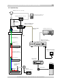
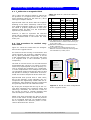
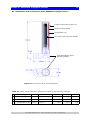
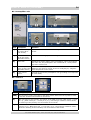
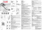
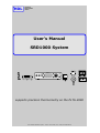
2. Installation system components (continued)
14
2.5. System map
test box (Section 2.3.6, Annex B6)
T B X -1 0 t e s tb o x
resistance meter (Section 2.3.6)
current meter (Section 4.2.1)
ACS-10 (Section 4.2.1, Annex D)
ACS-10
adjustable DC current source
test plug
(Section 2.4.3)
MIDS-10 preamplifier unit
(Section 2.4.1, Annex B5)
5-way black
cables
(Annex B7)
8-way grey cable
(Annex B7)
oscilloscope (Section 2.4.3)
cryostat connector
(Section 2.3.5, Annex B7)
cryostat
system
normal conductive
shielded twisted pairs
MIDS-10 control unit
(Section 2.4.1, Annex B2/3)
thermal anchoring /
connector
MIDS-10
T > 9 K level
mutual inductance detection system
T < 9 K level
MIDS-10 mains adapter
(Section 2.4.1, Annex B4)
superconductive shielded
twisted pairs (Section 2.3.4)
thermal anchoring
digital voltmeter
(Section 2.4.2)
DMM
computer
cryogenic sensor
(Section 2.3,
Annex A)
optical interface
EMI-filter
SRD1000
DCS-10
(Section 3.2, Annex C)
DCS-10
demagnetisation coil supply
thermal plate: 14 mK < T < 1.2 K
User’s Manual SRD1000 System, version: 06-02-2006, HDL, Leiden, The Netherlands