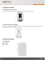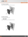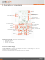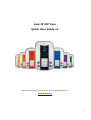
1
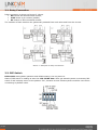
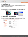
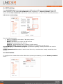
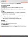
Link IP iDP Cam
Quick User Guide v1
Please find the latest version of the manual and firmware at :
www.linkcom.fr
1
CLAMART–
Index
1. Physical install .......................................................................................................................................................... 3
1.1. Opening the door phone ...................................................................................................................................................3
1.2. Dismounting of nameplate ...............................................................................................................................................3
2. Wall mounting ........................................................................................................................................................... 3
2.1. Dimension ..............................................................................................................................................................................3
2.2. Surface mounting.................................................................................................................................................................4
2.3. Flush mounting.....................................................................................................................................................................4
3. Description of components ................................................................................................................................... 5
3.1. PoE or Power Supply ..........................................................................................................................................................5
3.2. Relay Connection .................................................................................................................................................................6
3.3. DIP Switch ..............................................................................................................................................................................6
4. Setting ........................................................................................................................................................................... 7
4.1. P2P or SIP server Mode .....................................................................................................................................................7
4.2. Web interface access ..........................................................................................................................................................7
4.3. Network settings: DHCP or fixed IP mode ..................................................................................................................7
4.4. SIP setting ...............................................................................................................................................................................8
4.5. Call button ..............................................................................................................................................................................8
5. Operation testing...................................................................................................................................................... 9
5.1. Outgoing call :........................................................................................................................................................................9
5.2. Incoming call : .......................................................................................................................................................................9
5.3. Video ........................................................................................................................................................................................9
5.4. Triggering relays .................................................................................................................................................................9
6. Reset.............................................................................................................................................................................. 9
6.1. Default setting.......................................................................................................................................................................9
6.2. Default Ip setting .................................................................................................................................................................9
2
CLAMART–
1. Physical install
1.1. Opening the door phone
Using the tool provided, unscrew the screw, as shown below and remove the cover:
1.2. Dismounting of nameplate
Remove the 4 screws of the transparent protection. Make the appropriate changes on the nameplate and
mount the protection using 4 screws.
2. Wall mounting
2.1. Dimension
Height: 182mm
Width: 104mm
Depth:: 22mm
p.3 | 23
2.2. Surface mounting
Using 3 screws and plugs, fix the doorphone to the wall:
2.3. Flush mounting
The dimensions of the flush part are:
• Height: 182mm
• Width: 104mm
• Depth: 22mm
Using 3 screws and plugs, fix the doorphone to the wall:
p.4 | 23
3. Description of components
Switch
Sensitivity sensor
ambient light
RJ45 LAN port
Cover connector
(Speaker, camera,…)
12V Out
12V Power supply
DS1 and DS2 Input
Relay 1
Micro volume
Relay 2
Speaker volume
l
Jumper,
to disable LED
Handicapped norm LED
Button 4
Button 2
Label LEDs
Button 3
Button 1
Handicapped norm LED : indicate the status of doorphone :
• Green LED : Ringing.
• Blue LED : In call
• Red LED : door opening
3.1. PoE or Power Supply
For Link IP iDP Cam is necessary used PoE power from switch or the AC voltage of 11-15V or DC
voltage of 12-15V, not exceed 300mA.
In practice the alternating feeder 12V/1A mostly meets these demands.
p.5 | 23
3.2. Relay Connection
Relay connection is shown on Picture 2. Where
• NO means idle-disconnected contact,
• COM means a pin contact (middle)
• NC means an idle-connected contact.
The contacts of both switches are galvanically isolated from each other and from the circuits.
Picture 1 Examples of relays connections
3.3. DIP Switch
DIP switch setting basic operation and default setting. See on picture 4.
State of DIP switch is reading at start the Link IP iDP Cam. After get started system is necessary DIP
switch 3 and 4 always return to the position "On", because at next reboot system would be new values
overwriting by default value.
p.6 | 23
4. Setting
4.1. P2P or SIP server Mode
The Link IP iDP Cam works in P2P or SIP server mode. The mode setting depends on the Dip Switch
position. In SIP server mode it is possible to register the doorphone to IP-PBX or SIP operator.
In P2P mode, the doorphone calls a IP address.
4.2. Web interface access
In your web browser enter IP address of the Link IP iDP Cam, default is « 192.168.1.250 ». See
Image 4. Enter user name and password. default User name is « admin », password is « 1234 ».
4.3. Network settings: DHCP or fixed IP mode
In Network setting menu, It is possible to use DHCP automatic setup or enter manually IP addresses.
After making all changes click on a « save and restart » button. Restarting is mandatory for those
steps.
p.7 | 23
4.4. SIP setting
The Link IP iDP Cam can be set to peer to peer (P2P) mode or SIP server mode by setting the DIP
switch (page 8). In P2P mode Link IP iDP Cam calls IP address in « memory number» (page 15).
If you set the Link IP iDP Cam to SIP server mode by DIP switch, so add in menu item SIP parameters.
SIP server mode setting:
Enter the SIP parameters:
• Name or IP address of IP-PBX in “SIP proxy server”
• Account module :
Name : user name (or number) of SIP account
Password : password of SIP account
Auth. Id : Authentification id (or number) of SIP account
Expiration time : Interval of sending requests for re-registration in SIP server
Use 180 Ringing or 183 Session progress : preanswer signaling. Usually works and not need to
change it.
Enable Symmetric RTP: enable in case of voice flow only in one direction. Usually needed by Cisco
devices.
4.5. Call button
To configure the numbers that will be called when pressing the buttons, go to the "Memory numbers"
menu:
p.8 | 23
In SIP server mode, enter for each button, the call number. In P2P mode, enter for each button, the IP
address (in the form a * b * c * d) desired destination. Then click "Save changes".
5. Operation testing
5.1. Outgoing call :
Press a button, the IP Link iDP Cam must call the extension number previously configured.
5.2. Incoming call :
The Link IP iDP Cam accepts incoming calls. Upon receiving a SIP call, it picks up on the first ring by
default.
5.3. Video
The video is available on Link IP iDP Cam home page. It is also available at the following addresses:
• http://<IP_DoorPhone>/video.jpg (jpg image) • http://<IP_DoorPhone>/video.mjpg (mjpg video) • rtsp://<IP_DoorPhone> (H.264/H.263 streaming)
• Link Door Manager software for Windows, iPhone/iPad or Android.
5.4. Triggering relays
During call with the DoorPhone, type "55" to activate relay 1 or "66" to activate relay 2. (Default
setting). The relays can also be activated remotely by http commands:
• http://<IP_DoorPhone>/cgi-bin/remctrl.sh?id=relay1 (activate the 1st relay)
• http://<IP_DoorPhone>/cgi-bin/remctrl.sh?id=relay2 (activate le 2st relay)
6. Reset
6.1. Default setting
The Switch 3 allows to return to the default configuration: switch OFF the switch 3 and restart the
doorphone. After restart, switch ON (normal) the switch number 3.
6.2. Default IP setting
The Switch 4 allows returning the default IP setting: Switch OFF the switch number 4 and restart the
doorphone. You can now access the doorphone on "192.168.1.250" IP address. After restart, switch ON
(normal) the switch number 4.
p.9 | 23