1
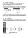
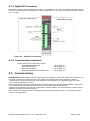
4. INSTALLATION
PRECAUTION: Please read this manual carefully before you install the instrument. If you apply all
recommendations in this chapter you will increase the reliability and long term performance of your system.
4.1. Recommendations
4.1.1. Control Cabinet Design
Warning: Please follow the following warnings for designing the control cabinet which will increase the
reliability of your system.
The control cabinet should be designed therefor the MCS-08AD modules can operate safely. The panel should
be placed in a clean area, without getting direct sun light if possible, with a temperature between -10 ºC and
+40 ºC, humidity not exceeding 85% non-condensing. All external cables should be installed safely to avoid
mechanical damages.
MCS-08 modules are very low level signal measuring instruments. To avoid electrical noise, the instruments
should be separated from equipment that produces electrical noise. Preferably use a metal cabinet against
radio frequency interference, to protect against electromagnetic disturbance the cabinet shall be connected to
ground. Keep the load cell cable trays separated from others, if possible. If there is noise-generating equipment
such as heavy load switches, motor control equipment, inductive loads etc., please be careful against the EMC
interference in the cabinet. If possible protect MCS-08 modules by a Faraday cage or install them in a separate
section or install them far a way from this kind of equipment. Install parallel reverse diodes to the DC inductive
loads like relays, solenoids etc. to minimize voltage peaks on the DC power lines.
4.1.2. Cabling
All cables coming to the control cabinet shall be shielded. Please use separate cable trays for these low signal
level cables. Distance from load cell cables, interface cables and DC power supply cables to power line cables
shall be 50 cm at minimum.
4.1.3. Mechanical Installation
After designing the control panel and installing DIN rails according to the recommendation in this chapter, install
the N-bus connectors on the DIN rail as shown in figure 4.1.
Figure 4.1 – N-bus connectors installed on DIN-rail
Place the modules on the DIN rail for making the connection between the N-bus and the MCS-08 modules as
shown on figure 4.2. Be sure that the mechanical installation and the N-Bus connection of the modules are
done properly.
Figure 4.2 – Installation on DIN-rail
MCS-08 Technical Manual, Rev. 1.04 December 2012
Page 11 of 52