1
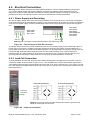
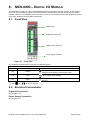
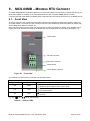
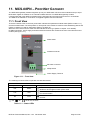
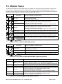
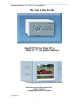
8. MCS-08IO – DIGITAL I/O MODULE
The MCS-08IO module has 4 opto-isolated digital inputs and 4 potential-free relay outputs. All I/O control is
done over the external bus system or the xFace software. Please refer to the data structure of the related
gateway module for the available input and output commands. For example, with a Profibus gateway all input
and output conditions are by Profibus commands.
8.1. Front View
Status LEDs
Digital input connector
Digital output connector
Power Supply Terminal
Figure 8.1 – Front view
The meanings of these LEDs in operation are described below.
LED
Symbol
Name
Description
Module is energized
Pwr
Power
Module is de-energized. Check power cable
Lnk
Link
Err
Error
Off
On
Input / output state changed
Error. Refer to error table in chapter 14
No error
Off for 0.3 seconds
8.2. Electrical Connections
Digital I/O Connection
See chapter 4.2.3
Power Supply Connection
See chapter 4.2.1
MCS-08 Technical Manual, Rev. 1.04 December 2012
Page 36 of 52