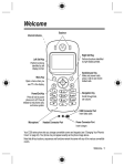
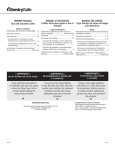
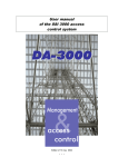
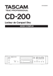
1
USER MANUAL SOLO User Manual SOLO DRM Generator User Manual History of modification of this document Revision Date Product version Modified sections Comments A 29/11/05 Preliminary - Creation WARNING This document contains preliminary information about SOLO. DIGIDIA reserves the right to make changes at any time without prior notice in order to improve design and supply the best possible product. This document includes some confidential information. It can not be copied, otherwise reproduced, translated into another language or transmitted without prior written authorisation from DIGIDIA. Page 2/23 SOLO User Manual TABLE OF CONTENTS 1INTRODUCTION.................................................................................................................... 4 2PRODUCT PRESENTATION................................................................................................ PRESENTATION................................................................................................ 5 3FEATURES AND PERFORMANCES.................................................................................... 6 3.1Generalities.................................................................................................................................... 6 3.1Generalities....................................................................................................................................6 3.2Input interfaces............................................................................................................................... interfaces...............................................................................................................................7 3.3Output interfaces............................................................................................................................ 8 interfaces............................................................................................................................8 3.4Control/Monitoring ways................................................................................................................. 8 ways.................................................................................................................8 3.5Power requirements..................................................................................................................... 10 requirements.....................................................................................................................10 3.6Safety requirements..................................................................................................................... 10 requirements.....................................................................................................................10 3.7EMC compliance.......................................................................................................................... 10 compliance..........................................................................................................................10 3.8Transport requirements................................................................................................................ 11 requirements................................................................................................................11 3.9Storage requirements................................................................................................................... requirements...................................................................................................................11 11 3.10Environmental requirements .....................................................................................................11 .....................................................................................................11 3.11Mechanical Characteristics........................................................................................................ ........................................................................................................12 12 Characteristics 4GETTING STARTED........................................................................................................... STARTED........................................................................................................... 13 4.1Unpacking the SOLO rack........................................................................................................... 13 rack...........................................................................................................13 4.2First start up................................................................................................................................. 13 up.................................................................................................................................13 5MAINTENANCE................................................................................................................... 5MAINTENANCE................................................................................................................... 15 5.1Reading the log file...................................................................................................................... 15 file......................................................................................................................15 5.2Updating the firmware or dowloading a new MDI file................................................................... 15 file...................................................................15 5.3First level maintenance................................................................................................................ 15 maintenance................................................................................................................15 5.4Precautionary maintenance......................................................................................................... 16 maintenance.........................................................................................................16 6APPENDIX........................................................................................................................... 6APPENDIX........................................................................................................................... 17 6.1Glossary....................................................................................................................................... 17 6.1Glossary.......................................................................................................................................17 6.2References................................................................................................................................... 17 6.2References...................................................................................................................................17 6.3Front and rear panels................................................................................................................... ...................................................................................................................18 18 panels 6.4SOLO Control Software............................................................................................................... 19 Software...............................................................................................................19 6.5Warranty terms............................................................................................................................. terms.............................................................................................................................19 19 6.6Instructions in case of return to factory........................................................................................ 19 factory........................................................................................19 Page 3/23 SOLO User Manual 1 INTRODUCTION This document is the user manual for the SOLO product. It provides general information about the SOLO product, and detailed performance characteristics. This user manual is divided into 6 sections where the user can find all the necessary information for the installation, the usual operation and the first level maintenance of it. This part gives a general presentation of this manual. Section 1 – Introduction This part describes SOLO and its applications. Section 2 – Product presentation Section 3 – Features and performances This part provides detailed information about interfaces and operation of the SOLO product This part provides information about installation, Section 4 – Getting started configuration and normal operation of the SOLO produc This part explains how to make first level maintenance. Section 5 – Maintenance The appendixes give additional detailed information Section 6 – Appendix about the SOLO product and its operation. Page 4/23 SOLO User Manual 2 PRODUCT PRESENTATION SOLO belongs to the CHORUS DRM product line developed by DIGIDIA. The SOLO DRM Generator provided by DIGIDIA is fully compliant to the DRM standard and is specially designed for testing DRM in factory or in laboratory. This device performs the channel encoding process and the OFDM modulation of a single MDI (Multiplex Data Interface) file, which is embedded in the product. One sample file is delivered as a standard feature with the product. However, other files can be generated on-demand by DIGIDIA depending on the DRM profiles needed to perform the tests. These new files can be saved in the hard disk of any PC and easily dowloaded inside the product using the Web GUI, also available as a standard feature SOLO is a DRM Generator, which uses digital modulation to ensure the highest quality of the output signal. One single unit allows to easily feed any kind of DRM receivers or other related devices with a direct RF output signal available on a BNC connector as a standard feature. The center frequency can therefore be adjusted using the graphical user interface or the LCD. For a high output stability, an internal GPS receiver is also available as a standard feature. As an option, the SOLO DRM Generator is able to operate in simulcast mode (multiple channels) in order to broadcast AM and DRM programmes using the same transmitter. Main of the control and monitoring of the SOLO DRM Generator is done through an Ethernet link and using Internet Explorer running on any kind of computer. Alarms are monitored on front face LEDs and on a rear panel connector as relay contacts. Alarms can also be controlled and monitored by any standard SNMP managers (standard MIB). Also, basic setup and monitoring functions can be performed using a LCD available on the front panel as a standard feature. SOLO includes a high-density electronic board packaged in a 1U 19" rack and gives to the user, guarantees of reliability and robustness against severe environment including EMC constraints. Page 5/23 SOLO User Manual 3 FEATURES AND PERFORMANCES 3.1 Generalities SOLO Generator depicted in figure 1 provides: • • • • • • • • MDI file player to generate a DRM compliant signal; DRM modulation according to DRM standard and associated standards (see References); Direct RF output from 148.5 kHz to 27.0 MHz center frequency range; Digital audio input and analog audio input for AM modulation; Simulcast modulation option; HTTP control for remote access; LCD front panel for local control; SNMP alarms reporting and control; Analog Audio Digital Audio AM Input Selection AM/DRM Modulation MDI File Player MDI File GPS aerial RF Synthesizer AM/DRM Simulcast Possibility (option) GPS Receiver Clock Processing Supervision & Control Front Panel LCD Ethernet Alarms Figure 1: SOLO block diagram Page 6/23 RF SOLO User Manual Control, Monitoring, File downloading Web interface (HTTP) Ethernet - TCP/IP - RJ45 MDI File Downloading Audio Direct RF output Text Data SOLO DRM Generator MDI File DRM Settings To the DRM receivers AM Input MDI File generated by DIGIDIA Audio - One MDI sample file delivered (standard) - New files can be created on-demand - Center Frequency change (standard) - TCP/IP settings (standard) - AM/DRM switching (standard) - AM/DRM simulcast (optional) Remote settings through the Web interface (standard) or locally through the LCD (standard) Figure 2: SOLO implementation 3.2 Input interfaces A three-digit label [xxx] enables to locate each connector (see Appendix). 3.2.1 • • Audio inputs AES AUDIO IN [102]: • XLR Female • AES/EBU ANALOG AUDIO IN [103]: • 3.2.2 • XLR Female Internal GPS receiver GPS ANT. IN [104]: • GPS Signal Input • Output power supply of the active antenna • Voltage: 5V • Current: 50 mA max. • GPS TNC connector (50 Ω) Page 7/23 SOLO User Manual 3.3 Output interfaces • CARRIER OUT [106]: • Direct RF output (DRM spectrum) • BNC female connector • Level: 0dBm typical • Frequency range: 148.5kHz to 27MHz 3.4 Control/Monitoring ways 3.4.1 • • Ethernet Ethernet 1 [100]: • RJ45 (10/100baseT) • SNMP (V1 et V2c), FTP and HTTP protocols Ethernet 2 [101]: • RJ45 (10/100baseT) • SNMP (V1 et V2c), FTP and HTTP protocols 3.4.2 • DB9 debug port RS232 connector [107]: 3.4.3 • DB15 female connector Relay contacts Alarms connector [108]: • DB9 female connector • Each contact is connected to a relay contact • Maximum voltage = 30V DC • Maximum current = 0,2A DC • Maximum voltage between open contacts: 400V AC (50Hz), Page 8/23 SOLO User Manual CONTACT 1 CONTACT 2 CONTACT 3 CONTACT 4 GND 1 2 3 4 5 6 7 8 9 CONTACT CONTACT CONTACT CONTACT CONTACT x 1 2 3 4 CONTACT x Figure 3: Alarm connector pin-out . In a normal errorless operation all the contacts are closed. Alarms are signalled by open contacts. When the equipment is not under power, all relay contacts are opened (alarm state). The alarm contacts can be dedicated to any kind of error combination using the PC control software. • Contact 1, 2, 3 : programmable alarm conditions • Contact 4 : power supply alarm The power supply alarm is active when at least one power supply voltage is out of operation. 3.4.4 LEDs on the Front panel SOLO equipment can detect many types of alarms. A summary of these alarms is displayed on the front panel. Alarms are grouped in two categories: • Fault [200]: critical error(s) • Warning [201]: any non-critical alarm(s) Fault LED is switched on when one of the following alarms is detected: • MDI File error • Unsynchronized GPS in SFN mode, • System error: software problem detected, • Hardware problem: hardware problem detected, Warning LED is switched on when one of the following alarms is detected: • Unlocked GPS in SFN mode, The details of the alarms and the warnings are given through the SOLO control software. Power LED [202] is switched on when SOLO is switched on. Page 9/23 SOLO User Manual 3.5 Power requirements 3.5.1 Main voltage specifications The DIGIDIA equipment can be operated within the following ranges: Input voltage 85 to 264 volts 3.5.2 Frequency 47 to 63 Hz Fuse Protection Two fuses are located on the rear panel, inside the main socket [110], and identified by the label F1/F2. These fuses must be replaced by (or equivalent fuses): Main voltage 110/230 VAC Part N° F1T2A Rate 2A / 250V slow blow Manufacturer CEHESS Size 5 x 20 mm WARNING Equipment must be switch off and main line supply disconnected to network before all open operation or only by qualified staff. 3.6 Safety requirements Equipment connected to the mains by plug on TN or TT power systems, socket-outlet shall be installed near the equipment and shall be easily accessible. Class I equipment (only connected to a socket-outlet with a protective earth connection). Installation category II. Pollution degree 2. The SOLO equipment must be connected to earth in accordance to CEI364 (NFC15-100). 3.7 EMC compliance The SOLO equipment complies with the European Directives for Electromagnetic Compatibility (EMC 89/336/EEC). The equipment complies with the EN55022-B class and the EN50082-1 standards. EMC characteristics can be guaranteed only if input / output cables with appropriate shielding are used. It is necessary to establish a direct short connection between the earth connection point of the rack and any grounding point available on the bay or chassis in which the system is installed in order to meet EMC constraints. Page 10/23 SOLO User Manual 3.8 Transport requirements Use only the original packing for the transport of any equipment. WARNING The SOLO remains under guarantee only if this condition is met. 3.9 Storage requirements Recommended storage temperature Recommended relative humidity -20° C and +70° C. 10 to 80 % at 50°C 3.10 Environmental requirements 3.10.1 Temperature Correct operation of the SOLO equipment is insured in an ambient temperature between the following limits: + 0°C and + 50°C. Power dissipation of the product with all options installed does not exceed 20 W. 3.10.2 Cooling An internal fan cools SOLO. The airflow is entering the unit through the front panel and ejected through the rear panel. 3.10.3 Altitude The SOLO equipment can be used from sea level up to 4000 m over sea level. Page 11/23 SOLO User Manual 3.11 Mechanical Characteristics 3.11.1 Weight and dimensions (SOLO only). Weight: 5 kg • Dimensions (W x D x H): 0.483 m (19’’) x 0.450 m x 0.044 m (1 U) • 3.11.2 Weight and dimensions (SOLO in its original packing, ready for shipment). Weight: 7 kg • Dimensions (WxDxH): 0.570 m * 0.570 m * 0.170 m • Page 12/23 SOLO User Manual 4 GETTING STARTED 4.1 Unpacking the SOLO rack Check the packing against transport damage. If it is the case, please contact the carrier immediately. Be careful while unpacking, the equipment may be heavy and must be handled with care. Keep the original packing for further transport. Check the equipment against transport damage. Check if the expected electric cable and the user manual are provided. 4.2 First start up 6,80 mm The equipment must be installed in a 19 inch bay. Several holes are available on the front panel to tighten the rack inside the cabinet, as presented in the following diagram. 11 mm 8 mm WARNING: Service work described in this paragraph must be carried out by trained staff. Because of the weight of the rack, mounting it into a cabinet requires the rack to be supported by rails and not by the front panel only. 1. Install all necessary cables. 2. Make sure the equipment is correctly grounded. 3. Make sure the air flow around the equipment permits an optimal cooling. (Do not obstruct the blower output). No other equipment should be installed directly under and above the SOLO equipment. 4. Connect the power supply Page 13/23 SOLO User Manual WARNING: To prevent damage to the equipment, check the main voltage, current and frequency available which must be in the range of DIGIDIA specifications. 1. Switch on your device WARNING: SOLO can be controlled using a web browser installed on a computer. See Appendix for the configuration of the computer. On line help is available for every menu. The default settings are the next : • IP address port 1: 10.64.0.1 • IP address port 2: 10.16.0.1 • Subnet Masks : 255.240.0.0 • Gateway : 10.64.0.1 • Equipment name : SOLO • Equipment comment : NO COMMENT • User/Password : public/public (level 1); the level 1 is the less restricted access level. • LogFile : no event Page 14/23 SOLO User Manual 5 MAINTENANCE 5.1 Reading the log file SOLO includes a log file in which the 256 last events are stored. Use the web browser to read it. 5.2 Updating the firmware or dowloading a new MDI file Use the web browser to update the firmware and to download a new MDI file. Read the on line help for more information. 5.3 First level maintenance Because of the digital technology used in the DIGIDIA equipment, the first level maintenance is restricted to an exchange of the whole equipment. WARNING: Make sure the operator has an easy and safe access to the equipment. 5.3.1 Fuses replacement Two fuses are located in the rear panel socket (see Appendix). To check or replace them: • Switch the equipment off, • Remove the main cable, • If the fuse(s) is (are) blown, replace it (them) by the original reference provided by DIGIDIA, • When the fuses are back in their housing, connect again the main cable and switch the equipment ON, • Check the equipment normal operation, • Power supply check. A staff trained by DIGIDIA can only do the internal power supply replacement. A specific replacement procedure provided by DIGIDIA must be used in this intervention. 5.3.2 Rack replacement See the following « Uninstalling the equipment » section. 5.3.3 Uninstalling the equipment WARNING: Make sure the operator has an easy and safe access to the equipment. Switch the equipment off, and remove its corresponding main cable. Remove all other cables. Page 15/23 SOLO User Manual Remove all necessary screws, including its back plane screw. Extract the unit from its housing by pulling out the unit by its front panel handles. In case the equipment is replaced by a spare one, see « First start-up » section. Check that the place is still safe for the operation of the rest of the equipment in the bay. 5.4 Precautionary maintenance 5.4.1 Fan The life span of the fan is typically 45 000 hours (about 5.1 years). DIGIDIA recommends changing them every five years. Fan can be changed during operation (Ref. 412H from PAPST) but contact the DIGIDIA customer service. 5.4.2 Battery The battery that protects internal Real Time Clock must be change every ten years in case of spare device (Ref. CR1225 from RENATA). Please contact the DIGIDIA customer service. Page 16/23 SOLO User Manual 6 APPENDIX 6.1 Glossary GPS http SFN SNMP TCP / IP : Global Positioning System : Hyper Text Tranfer Protocol : Single Frequency Network : Simple Network Management Protocol : Internet Suite of Protocols 6.2 References [1] ETSI ES 201 980: Digital Radio Mondiale (DRM); System Specification. [2] ETSI TS 102 820: Digital Radio Mondiale (DRM); Multiplex Distribution Interface (MDI). [3] ETSI TS 102 821: Digital Radio Mondiale (DRM); Distribution and Communications Protocol (DCP). [4] EN 550022-B: "Limits and methods of measurement of radio interferences characteristics of information technology equipment". [5] EN 50082-1: "Generic immunity standard –Part 1: Domestic commercial and light industry". Page 17/23 SOLO User Manual 6.3 Front and rear panels Page 18/23 SOLO User Manual 6.4 SOLO Control Software SOLO can be controlled using a web browser installed on a computer. 6.4.1 System required A computer with Windows (Millenium, NT, 2000 or XP) is required with Internet Explorer 6.0 (or higher) and JavaScript V1.5 installed. A network board have to be installed on this computer with the next settings : • IP address : 10.64.x.y with x and y different of the SOLO IP address (x ≠ 0 or y ≠ 1) in the case of the default IP address of SOLO (10.64.0.1) • Subnet Mask : 255.240.0.0 corresponding to the default subnet mask of SOLO. The connection between SOLO and the computer can be made directly with a RJ45 crossed cable. To check to the good network settings, ping the SOLO device in a DOS window (ping 10.64.0.1). 6.4.2 Control the SOLO To control SOLO : • Launch Internet Explorer, • Fill in the address field : http://10.64.0.1 (10.64.0.1 corresponds to the default IP address of SOLO). Automatically, the welcome page appears. For more information about the control software, please read the on-line help. 6.5 Warranty terms 6.5.1 Standard product warranty This DIGIDIA product is warranted against defects in material and workmanship for a period of one year from date of shipment. During the warranty period, DIGIDIA will, at its option, either repair or replace products which prove to be defective, free-of charge. For warranty service or repair, this product must be returned to DIGIDIA France. Buyer shall prepay shipping charges to DIGIDIA and DIGIDIA shall pay shipping charges to return the product to buyer. Products returned for repair outside of the warranty period will be charged on a per unit basis. Per unit charges are established for each product repair as they arise. On request, a customer / supplier contract may be established for extending these warranty terms on a yearly basis. 6.5.2 Limitation of warranty The foregoing warranty shall not apply to defects resulting from improper or inadequate maintenance by Buyer, Buyer-supplied software or interfacing, unauthorized modification or misuse, operation outside of the environmental specifications for the product, or improper site preparation or maintenance. 6.6 Instructions in case of return to factory In case you need to return your equipment to DIGIDIA for updating or maintenance, please use the following procedure: Page 19/23 SOLO User Manual • • • • • • • Call the hot line at DIGIDIA before shipping your equipment, in order to check whether it is really necessary to return it. The shipment back to DIGIDIA is organised by the customer and at his expense and DIGIDIA will organise and pay the return after repair to the customer’s company. If you are part of an EEC country, the shipment is at your expense until DIGIDIA’s premises. If you are outside EEC, the shipment is at your expense until RENNES SAINT-JACQUES airport (France). During the guarantee period, the repair is free of charge. If your equipment is out of guarantee and if you have no maintenance contract (*), DIGIDIA will send you by fax a quotation for this repair that you have to acknowledge by sending the form back. Always use the original packing in which the equipment had been delivered to you. Do not return any documentation or cables (power cord or other). Use the attached form to explain the reason of the return and, when necessary, the problems encountered. Send the equipment to: DIGIDIA Support Department Immeuble Orchis Les landes d'Apigné 35650 LE RHEU - France Tel: +33 (0)2 99 14 63 32 Fax: +33 (0)2 99 14 58 83 Email:[email protected] (*) If you want to set up a maintenance contract, please contact our sales department. Page 20/23 Model of report for return to factory From: Telephone: Company: Telefax: Under guarantee Other ( quotation will be submitted) Under a maintenance contract Type of system: SOPRANO ALTO DIAPASON SOLO Reason of return: Update Upgrade Maintenance Type of problem: Hardware Software Undefined EQUIPMENT SERIAL NUMBER FIRMWARE VERSION PC SOFTWARE NAME/VERSION EQUIPMENT SPECIFICITY (option, embedded boards, modem, etc.) Immeuble Orchis Les landes d'apigné -F-35560 LE RHEU Tel:+33 (0)2 99 14 63 32 - Fax:+33 (0)2 99 14 58 83 – Email: [email protected] ELECTROMAGNETIC COMPLIANCE STATEMENT (EEC directive 89/336 article 10) Manufacturer name: Address: DIGIDIA Immeuble Orchis Les landes d'apigné 35650 LE RHEU - FRANCE Equipment designation: XXXXXXX SOLO M. OLIVIER Pascal, Manager Declare having the strong presumption that the above designated equipment complies with the essential EEC89/336 directive requirements, by application of the standards listed below: NF EN 55022-B class NF EN 50082-1 Le Rheu, August 2000 Immeuble Orchis Les landes d'apigné -F-35560 LE RHEU Tel:+33 (0)2 99 14 63 32 - Fax:+33 (0)2 99 14 58 83 – Email: [email protected] SAFETY COMPLIANCE STATEMENT (EEC directive 73/23) Manufacturer name: Address: DIGIDIA Immeuble Orchis Les landes d'apigné 35650 LE RHEU - FRANCE Equipment designation: XXXXXXX SOLO M. OLIVIER Pascal, Manager Declare having the strong presumption that the above designated equipment complies with the essential EEC73/23 directive requirements, by application of the standards listed below: NF EN 60950 Le Rheu, August 2005 Immeuble Orchis Les landes d'apigné -F-35560 LE RHEU Tel:+33 (0)2 99 14 63 32 - Fax:+33 (0)2 99 14 58 83 – Email: [email protected]